Appendix D. Reading Schematic Diagrams
In most of this book I’ve given very detailed illustrations to describe how to assemble the circuits, but as you can imagine, it’s not exactly a quick task to draw one of those for each experiment you might want to document.
Similar issues arise, sooner or later, in every discipline. In music, after you write a nice song, you need to write it down using musical notation.
Engineers, being practical people, have developed a quick way to capture the essence of a circuit in order to be able to document it and later rebuild it or pass it to somebody else.
In electronics, schematic diagrams (or schematics) allow you to describe your circuit in a way that is understood by the rest of the community. Individual components are represented by schematic symbols that are a sort of abstraction of either the shape of the components or the essence of them. For example, the capacitor is made of two metal plates separated by either air or plastic; therefore, its symbol is as shown in Figure D-1.

Figure D-1. Schematic symbol for a capacitor
Another clear example is the inductor, which is built by winding copper wire around a cylindrical shape; consequently, the symbol looks like Figure D-2.
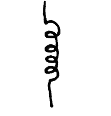
Figure D-2. Schematic symbol for an inductor
The connections between components are usually made using either wires or tracks on the printed circuit board and are represented on the diagram as simple lines. When two wires are connected, the connection is represented by a big dot placed where the two lines cross, as shown in Figure D-3.
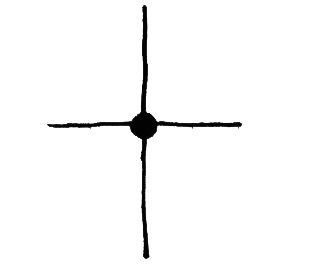
Figure D-3. Schematic symbol showing connected wires
This is all you need to understand basic schematics. Figure D-4 shows schematic symbols for components that are commonly found in Arduino circuits.
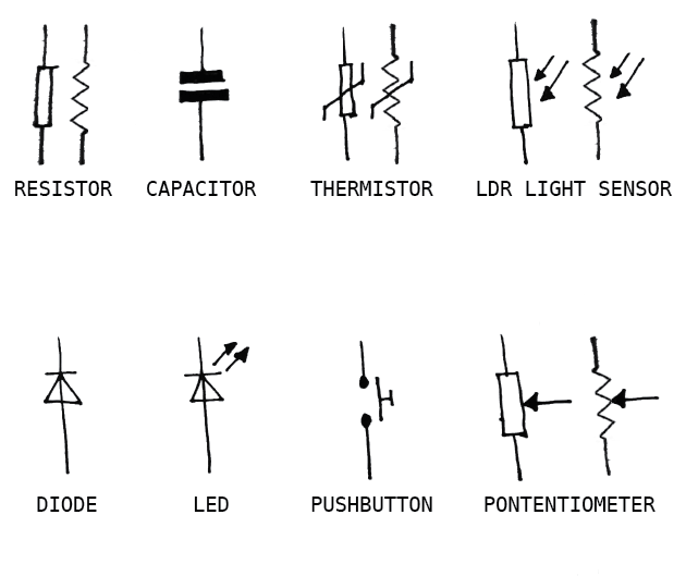
Figure D-4. Common schematic symbols seen in Arduino circuits
You may encounter variations in these symbols (for example, both variants of resistor symbols are shown here). See Wikipedia for a larger list of electronics symbols.
In addition to this (somewhat) standard set of symbols, there are conventions for how schematics are organised. Schematics are drawn so that information flows from left to right. For example, a radio would be drawn starting with the antenna on the left, following the path of the radio signal as it makes its way to the speaker, which would be the last thing on the right.
Figure D-5 describes the pushbutton circuit shown earlier in this book.
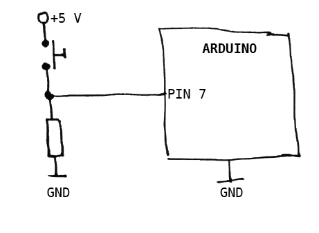
Figure D-5. A pushbutton connected to an Arduino digital input
You can see that the Arduino has been reduced to a box with a pin and GND, because these are the only important things to know about Arduino for this particular circuit. You can also see two wires that are shown connected the label GND. This means the wires are connected together. Connecting wires via labels is useful for connections that get very busy (such as GND) or have to get from one side of the schematic to the far side, crossing many other wires and components.
Chapter 8 shows many practical examples of schematics, and “Electronic Schematic Diagrams” discusses schematic diagrams in a little more detail.