Chapter 5. Advanced Input and Output
What you have just learned in Chapter 4 are the most elementary operations we can do in Arduino: controlling digital output and reading digital input. If Arduino were some sort of human language, those would be two letters of its alphabet. Considering that there are just five letters in this alphabet, you can see how much more work we have to do before we can write Arduino poetry.
Trying Out Other On/Off Sensors
Now that you’ve learned how to use a pushbutton, you should know that there are many other very basic sensors that work according to the same principle:
- Toggle switch
-
The pushbutton that you’ve been using is a type of switch called a momentary switch, because once you let it go, it goes back to where it was. A common example of a momentary switch is a doorbell.
In contrast, a toggle switch stays where you put it. A common example of a toggle switch is a light switch.
In this book we’ll use the common names for these switches: a pushbutton refers to a momentary switch, while a switch refers to a toggle switch.
Although you might not think of a switch as a sensor, in fact it is: a pushbutton (momentary switch) senses when you are pressing it, and a (toggle) switch senses (electrically) and remembers (mechanically) the last state you put it in.
- Thermostat
-
A switch that changes state when the temperature reaches a set value.
- Magnetic switch (also known as a reed switch)
-
This has two contacts that come together when they are near a magnet; often used for burglar alarms to detect when a door or window is opened.
- Carpet switch
-
A flat mat-like switch that can be placed under a carpet or a doormat to detect when a human being (or heavy cat) steps on them.
- Tilt switch or tilt sensor
-
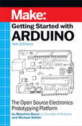
A simple but clever sensor that contains two (or more) contacts and a little metal ball (or a drop of mercury, but I don’t recommend using that). Figure 5-1 shows the inside of a typical model.
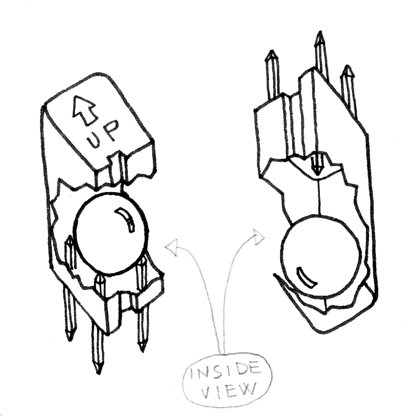
Figure 5-1. The inside of a tilt sensor
When the sensor is in its upright position, the ball bridges the two contacts, and this works just as if you had pressed a pushbutton. When you tilt this sensor, the ball moves, and the contact is opened, which is just as if you had released a pushbutton. Using this simple component, you can implement, for example, gestural interfaces that react when an object is moved or shaken.
Another useful sensor that is often found in burglar alarms is the passive infrared, or PIR, sensor, shown in Figure 5-2. This device changes state when a moderate infrared source, like a human, moves within its proximity. These sensors are often designed to detect humans but not small animals, so that burglar alarms won’t get triggered by pets.
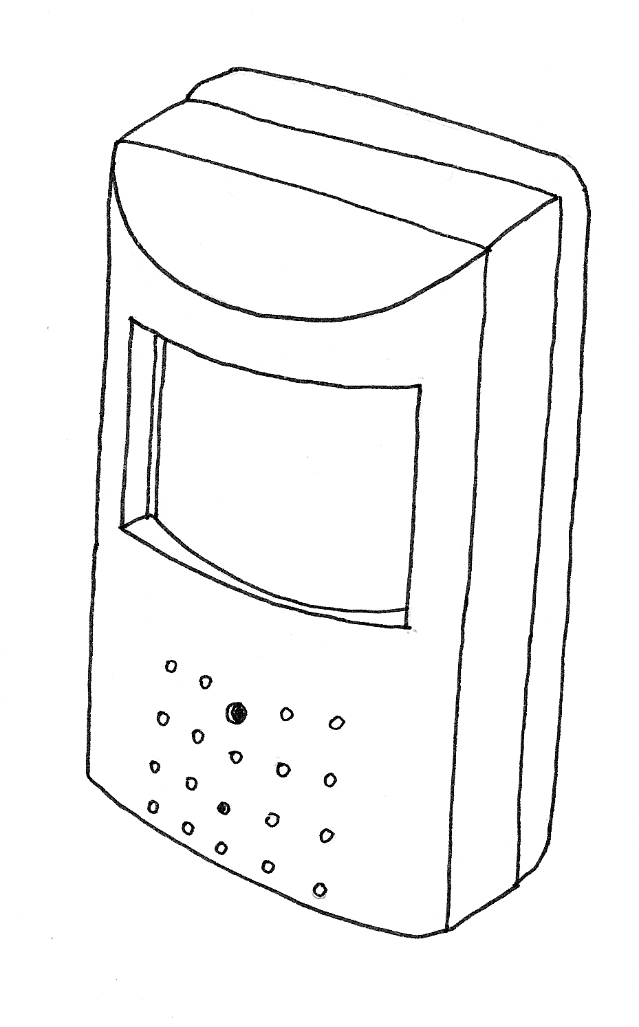
Figure 5-2. Typical PIR sensor
Detecting humans is actually quite complicated, and the PIR sensor is quite complex inside. Fortunately, we don’t really care about the insides. The only thing we need to know is that it results in a digital signal, indicating whether a human is present or not. This is why the PIR sensor is a digital sensor.
Homemade (DIY) Switches
You can make your own tilt switch with a metal ball and a few nails, and by wrapping some wire around the nails. When the ball rolls to one side and rests on two of the nails, it will connect those wires.
You can make a momentary switch with a clothespin by wrapping a wire around each handle. When the handles are squeezed, the switch is closed.
Alternatively, you can wrap the wires around the jaws of the clothespin, and put a piece of cardboard between them to keep the wires from touching. Tie a piece of string to the cardboard and tie the other end of the string to a door. When the door is opened, the string pulls the cardboard out, the wires touch, and the switch is closed.
Because all of these sensors are digital, any of them can be used in place of the pushbutton that you worked with in Chapter 4 without having to make any changes to your sketch.
For example, by using the circuit and sketch from “Using a Pushbutton to Control the LED”, but replacing the pushbutton with a PIR sensor, you could make your lamp respond to the presence of human beings, or you could use a tilt switch to build a lamp that turns off when it’s tilted on one side.
Controlling Light with PWM
You already know enough to build an interactive lamp, but so far the result is a little boring, because the light is only either on or off. A fancy interactive lamp needs to be dimmable. To solve this problem, we can use a little trick that makes a lot of things possible, such as TV or cinema. This trick is called Persistence of Vision, or POV. POV takes advantage of the fact that our eyes can’t “refresh” what they see more than about 10 times per second. If what we’re looking at changes more rapidly than that, the eye “blurs” one image into the other, creating the illusion -- some say “interpretation” -- of movement.
As we hinted at after the first example in Chapter 4, if you reduce the numbers in the delay function until you don’t see the LED blinking anymore, you will notice that the LED seems to be dimmer than its normal brightness. If you experiment with this, you will notice that if you make the on delay different from the off delay, you can make the LED appear brighter by leaving it on for longer, and you can make the LED seem to be dimmer by leaving it off for longer. This technique is called pulse-width modulation, or PWM, because you are changing the LED’s brightness by modulating (or changing) the width of the pulse. Figure 5-3 shows how this works. This works because thanks to persistence of vision, our eyes can’t see the distinct changes in the LED, because they’re happening too fast.
Pulse Width Modulation works with some devices other than an LEDs. For example, you can change the speed of a motor in the same way. In this case, it isn’t our eyes that allow this to happen, but rather the motor itself, because it can’t start or stop turning instantly. It takes a small amount of time for the motor’s rotor to speed up and slow down. If we change the output (using digitalWrite()) faster than the motor can respond, it ends up turning at some intermediate speed, depending on how much time it’s turned on, and how much time it’s turned off.
While this trick is very useful, you probably felt that controlling the LED brightness by fiddling with the delays in your code is a bit inconvenient. Even worse, as soon as you want to read a sensor, send data on the serial port, or do almost anything else, the LED brightness will change, because any extra lines of code you add will take time to execute, which will change the amount of time the LED is on or off.
Luckily, the microcontroller used by your Arduino includes a special piece of hardware called a timer/counter. Timer/counters run independently of whatever program your microcontroller is performing and can very efficiently blink your LEDs while your sketch does something else. On the Uno, this hardware is implemented on pins 3, 5, 6, 9, 10, and 11. Specifically, once set up correctly, the timer/counters can automatically turn on a pin for a certain amount of time, and then turn it off for a different amount of time, all without affecting your program. If you draw a graph of the voltage at the pin, you will see that the pulses can vary in width; thus this technique is called Pulse Width Modulation, or PWM.
Figure 5-3. PWM in action
The function that handles PWM on the Arduino is called analogWrite(). analogWrite() takes a value between 0 and 255, where 255 means full brightness and 0 means completely off.
analogWrite(9,50) will set the brightness of an LED connected to pin 9 to quite dim, while writing analogWrite(9,200) will set the brightness of the LED to quite bright. If you connect a motor to pin 9, analogWrite(9,50) will move the motor quite slowly, while writing analogWrite(9,200) will make the motor move much faster.
Note
Having multiple PWM pins is very useful. For example, if you buy an RGB LED (an LED that can emit red, green, and blue light in different intensities), you can adjust each value to make light of any colour.
Let’s try it out. Build the circuit that you see in Figure 5-4. You’ll need an LED of any colour and some 220-ohm resistors1.
Note that LEDs are polarized, which means they care which way the electric current goes through them. The long lead indicates the anode, or positive lead, and in our case should go to the right, which connects it to pin 9 of the Arduino. The short lead indicates the cathode, or negative lead, and in this case it should go to the left, connecting it to the resistor.
Most LEDs also have a flattened edge on the cathode side, as shown in the figure. An easy way to remember this is that the flat part looks like a minus sign, and that the short lead has had something subtracted from it.
As we mentioned in “Blinking an LED”, you should always use a resistor with an LED to prevent burning out the LED. Any value between 220 ohm resistor (red-red-brown) and 1000 ohm (brown-black-red) should be fine.
Then, create a new sketch in Arduino with the code shown in Example 5-1. You can also download it from the example code link on the book’s catalog page.
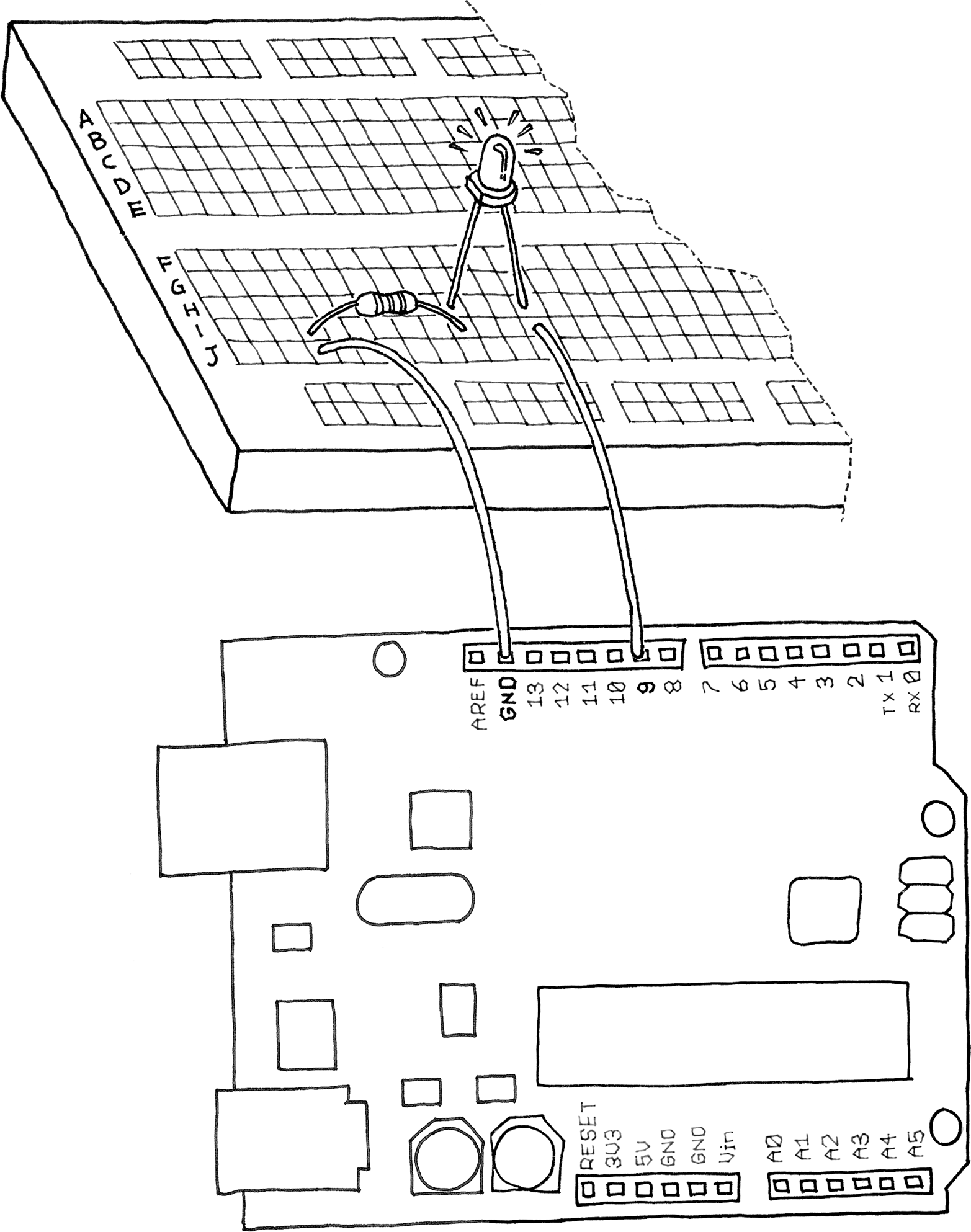
Figure 5-4. LED connected to PWM pin
Example 5-1. Fade an LED in and out, like on a sleeping Apple computer
constintLED=9;// the pin for the LEDinti=0;// We'll use this to count up and downvoidsetup(){pinMode(LED,OUTPUT);// tell Arduino LED is an output}voidloop(){for(i=0;i<255;i++){// loop from 0 to 254 (fade in)analogWrite(LED,i);// set the LED brightnessdelay(10);// Wait 10ms because analogWrite// is instantaneous and we would// not see any change with no delay}for(i=255;i>0;i--){// loop from 255 to 1 (fade out)analogWrite(LED,i);// set the LED brightnessdelay(10);// Wait 10ms}}
Upload the sketch, and the LED will fade up and then fade down continuously. Congratulations! You have replicated a fancy feature of a laptop computer.
Maybe it’s a bit of a waste to use Arduino for something so simple, but you can learn a lot from this example.
As you learned earlier, analogWrite() changes the LED brightness. The other important part is the for loop: it repeats the analogWrite() and the delay() over and over, each time using a different value for the variable i as follows.
The first for loop starts the variable i with the value of 0, and increases it up to 255, which fades the LED up to full brightness.
The second for loop starts the variable i with the value of 255, and decreases it up to 0, which fades the LED all the way down to completely off.
After the second for loop, Arduino starts our loop() function over again.
The delay() is just to slow things down a bit so you can see the changing brightness; otherwise, it would happen too fast.
Let’s use this knowledge to improve our lamp.
Add the circuit we used to read a button (back in Chapter 4) to this breadboard. See if you can do this without reading past this paragraph, because I want you to start thinking about the fact that each elementary circuit I show here is a building block to make bigger and bigger projects. If you need to peek ahead, don’t worry; the most important thing is that you spend some time thinking about how it might look.
To create this circuit, you will need to combine the circuit you just built (shown in Figure 5-4) with the pushbutton circuit shown in Figure 4-5. If you’d like, you can simply build both circuits on different parts of the breadboard; you have plenty of room.
Take a look at Appendix A to learn more about the solderless breadboard.
If you’re not ready to try this, don’t worry: simply wire up both circuits to your Arduino as shown in Figure 4-5 and Figure 5-4.
Now for the next example: if you have just one pushbutton, how do you control the brightness of a lamp? You’re going to learn yet another Interaction Design technique: detecting how long a button has been pressed. To do this, we need to upgrade Example 4-5 from Chapter 4 to add dimming. The idea is to build an interface in which a press-and-release action switches the light on and off, and a press-and-hold action changes brightness.
Have a look at the sketch in Example 5-2. It turns on the LED when the button is pressed and keeps it on after it is released. If the button is held, the brightness changes.
Now try it out. As you can see, this interaction model is taking shape. If you press the button and release it immediately, you switch the lamp on or off. If you hold the button down, the brightness changes; just let go when you have reached the desired brightness.
Just as we said before about thinking about the circuit, try to spend a bit of time trying to understand the program.
Probably the most confusing line is this one:
if (state == 1 && (millis() - startTime) > 500) {This line of code checks to see if the button is held down for more than 500 ms by using a built-in function called millis(), which is just a running count of the number of milliseconds since your sketch started running. By keeping track of when the button was pressed (in the variable startTime), we can compare the current time to the start time to see how much time has passed.
Of course, this makes sense only if the button is currently pressed, which is why at the beginning of the line we check to see if state is set to the value of 1.
As you can see, switches are really pretty powerful sensors, even though they are so simple. Now let’s learn how to use some other sensors.
Use a Light Sensor Instead of the Pushbutton
Now we’re going to try an interesting experiment using a light sensor2, like the one pictured in Figure 5-5.
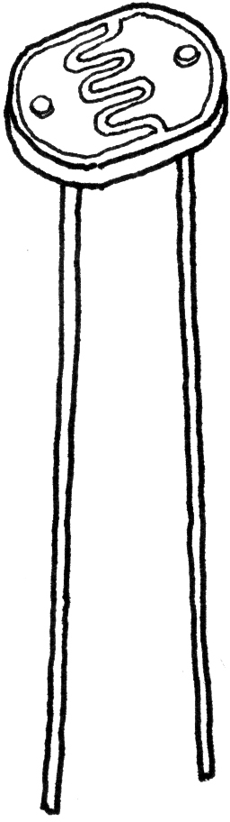
Figure 5-5. Light-dependent resistor (LDR)
As its name suggests, the light-dependent resistor (LDR) is some sort of resistor that depends on light. In darkness, the resistance of an LDR is quite high, but when you shine some light at it, the resistance quickly drops and it becomes a reasonably good conductor of electricity. It is thus a kind of light-activated switch.
Build the circuit shown in Figure 4-5 (see “Using a Pushbutton to Control the LED” in Chapter 4), and then upload the code from Example 4-2 to your Arduino. Press the pushbutton to make sure it works.
Now carefully remove only the pushbutton, and insert the LDR into the circuit exactly where the pushbutton was. The LED should come on. Cover the LDR with your hands, and the LED turns off.
You’ve just built your first real sensor-driven LED. This is important because for the first time in this book, you are using an electronic component that is not a simple mechanical device: it’s a real, rich sensor. In fact, this is only a small example of what the LDR can be used for.
Analogue Input
As you learned in the previous section, Arduino is able to detect whether there is a voltage applied to one of its pins and report it through the digitalRead() function. This kind of either/or response is fine in a lot of applications, but the light sensor that we just used is able to tell us not only whether there is light, but also how much light there is. This is the difference between an on/off or digital sensor (which tells us whether something is there or not) and an analogue sensor, which can tell us how much of something there is.
In order to read this type of sensor, we need to use a special Arduino pin.
Turn your Arduino around so it matches Figure 5-6.
In the top-left part of the board, you’ll see six pins marked Analog In; these are special pins that not only can tell you whether there is a voltage applied to them, but also can measure the amount of that voltage by using the analogRead() function. The analogRead() function returns a number between 0 and 1023, which represents voltages between 0 and 5 volts. For example, if there is a voltage of 2.5 V applied to pin number 0, analogRead(0) returns 512.
If you now build the circuit that you see in Figure 5-6, using a 10 K ohm resistor, and run the code listed in Example 5-3, you’ll see the onboard LED blinking at a rate that depends on the amount of light that shines on the sensor.
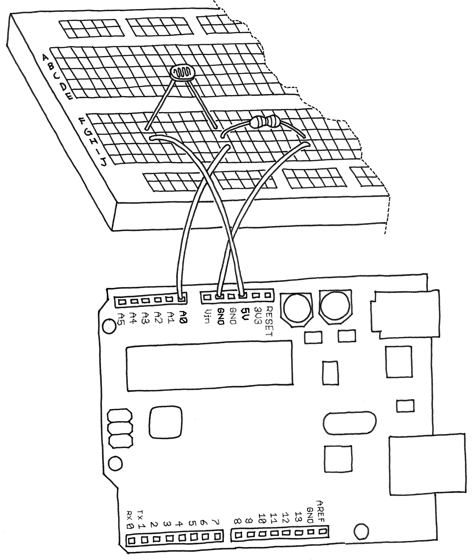
Figure 5-6. An analogue sensor circuit
Example 5-3. Blink LED at a rate specified by the value of the analogue input
constintLED=13;// the pin for the LEDintval=0;// variable used to store the value// coming from the sensorvoidsetup(){pinMode(LED,OUTPUT);// LED is as an OUTPUT// Note: Analogue pins are// automatically set as inputs}voidloop(){val=analogRead(0);// read the value from// the sensordigitalWrite(LED,HIGH);// turn the LED ondelay(val);// stop the program for// some timedigitalWrite(LED,LOW);// turn the LED offdelay(val);// stop the program for// some time}
Now add an LED to pin 9 as we did before, using the circuit shown in Figure 5-4. Because you already have some stuff on the breadboard, you’ll need to find a spot on the breadboard where the LED, wires, and resistor won’t overlap with the LDR circuit. You may have to move some things around, but don’t worry, this is good practice because it helps your understanding of circuits and the breadboard.
When you are done adding the LED to your LDR circuit, type in Example 5-4 and upload it to your Arduino.
Example 5-4. Set the LED to a brightness specified by the value of the analogue input
constintLED=9;// the pin for the LEDintval=0;// variable used to store the value// coming from the sensorvoidsetup(){pinMode(LED,OUTPUT);// LED is as an OUTPUT// Note: Analogue pins are// automatically set as inputs}voidloop(){val=analogRead(0);// read the value from// the sensoranalogWrite(LED,val/4);// turn the LED on at// the brightness set// by the sensordelay(10);// stop the program for// some time}
Once it’s running, cover and uncover the LDR and see what happens to the LED brightness.
As before, try to understand what’s going on. The program is really very simple, in fact much simpler than the previous two examples.
Note
We specify the brightness of the LED by dividing val by 4, because analogRead() returns a number up to 1023, and analogWrite() accepts a maximum of 255. The reason for this is that it is always desireable to read analog sensors with as much precision as possible, while our eyes can’t detect more subtle differences in the brightness of an LED. If you are wondering why analogRead() doesn’t return an even bigger range of numbers, it’s because that would occupy more space on the piece of silicon at the heart of the microcontroller, space that would have to come at the price of some other feature. Designing microntrollers is always a careful balance of features, space, heat, cost, and the number of pins.
Try Other Analogue Sensors
The light-dependent resistor is a very useful sensor, but Arduino cannot directly read resistance. The circuit of Figure 5-6 takes the resistance of the LDR and converts it to a voltage that Arduino can read.
This same circuit works for any resistive sensor, and there are many different types of resistive sensors, such as sensors that measure force, stretching, bending, or heat. For example, you could connect a thermistor (heat-dependent resistor) instead of the LDR and have an LED that changes brightness according to the temperature.
Note
If you do work with a thermistor, be aware that there isn’t a direct connection between the value you read and the actual temperature measured. If you need an exact reading, you should read the numbers that come out of the analogue pin while measuring with a real thermometer. You could put these numbers side by side in a table and work out a way to calibrate the analogue results to real-world temperatures. Alternately, you could use a digital temperature sensor such as the Analog Devices TMP36.
Up to now, we have used an LED as the output device. It would be difficult to measure temperature, for instance, by trying to judge how bright an LED is. Wouldn’t it be nice if we could actually get the values that Arduino is reading from the sensor? We could make the LED blink the values in Morse code, but there is a much easier way for Arduino to send information to us humans, using that same USB cable that you’ve been using to upload your sketches into the Arduino.
Serial Communication
You learned at the beginning of this book that Arduino has a USB connection that is used by the IDE to upload code into the microcontroller. The good news is that after a sketch is uploaded and is running, the sketch can use this same connection to send messages to or receive messages from from your computer. The way we do this from a sketch is to use the serial object.
In the Arduino programming language, anobject is a collection of related capabilities bundled together for convenience, and the serial object allows us to communicate over the USB connection. You can think of the serial object as a way to get a message to or from the Arduino, one character at a time. Of course, the serial object contains lots of complicated stuff that we don’t need to worry about. We just need to learn how to use the serial object.
In this example you’ll take the last circuit we built with the photoresistor, but instead of controlling the brightness of an LED, you’ll send the values that are read from analogRead() back to the computer. Type the code in Example 5-5 into a new sketch. You can also download it from the example code link on the book’s catalog page.
Example 5-5. Send the computer the values read from analogue input 0
constintSENSOR=0;// select the input pin for the// sensor resistorintval=0;// variable to store the value coming// from the sensorvoidsetup(){Serial.begin(9600);// open the serial port to send// data back to the computer at// 9600 bits per second}voidloop(){val=analogRead(SENSOR);// read the value from// the sensorSerial.println(val);// print the value to// the serial portdelay(100);// wait 100ms between// each send}
After you’ve uploaded the code to your Arduino, you might think that nothing interesting happens. Actually, your Arduino is working fine: it is busy reading the light sensor and sending the information to your computer. The problem is that nothing on your computer is showing you the information that is coming from your Arduino.
What you need is a software function called the serial monitor, and it’s built in to the Arduino IDE.
The Serial Monitor button is near the top-right corner of the Arduino IDE. It looks a bit like a magnifying glass, as if you were spying on the communication from the Arduino to your computer.
Click the Serial Monitor button to open the monitor, and you’ll see the numbers rolling past in the bottom part of the window. Cover up the photoresistor to make it darker, and see how the numbers change. Notice that the numbers never go below zero, and never go above 1023, as this is the range of numbers that analogRead() can produce.
This serial communication channel between Arduino and your computer opens up a whole new world of possibilities. There are many programming languages that let you write programs for your computer that can talk to the serial port, and through the serial port, those programs can talk to your Arduino.
A particularly good complement to Arduino is the Processing language), because the languages and IDEs are so similar. You’ll learn more about Processing in Chapter 6 in “Coding”, and your Arduino IDE includes some examples, such as File→Examples→04.Communication→Dimmer and File→Examples→04.Communication→Graph. You can also find many examples on the Internet.
Driving Bigger Loads (Motors, Lamps, and the Like)
Each of the pins on an Arduino board can only be used to power devices that use a very small amount of current, such as an LED. If you try to drive something big like a motor or an incandescent lamp, the pin might stop working, and could permanently damage the microcontroller that is the heart of your Arduino.
Warning
To be safe, the current going through an Arduino’s I/O pin should be limited to 20 milliamps.
Don’t worry, though. There are a number of simple techniques that allow you to control devices that use much more current. The trick is a bit like using a lever and fulcrum to lift a very heavy load. By putting a long stick under a big stone and a fulcrum in the right place, you can pull down on the long end of the stick, and the short end, under the stone, has much more force. You pull with a small force, and the mechanics of the lever apply a larger force to the stone.
In electronics, one way to do this is with a MOSFET. A MOSFET is an electronic switch that can be controlled by a small current, but in turn can control a much larger current. A MOSFET has three pins. You can think of a MOSFET as a switch between two of its pins (the drain and source), which is controlled by a third pin (the gate). It is a little like a light switch, where the gate is represented by the part you move to turn the light on and off. A light switch is mechanical, so it is controlled by a finger, but a MOSFET is electronic, so it is controlled by a pin from your Arduino.
Note
MOSFET means “metal-oxide-semiconductor field-effect transistor”. It’s a special type of transistor that operates on the field-effect principle. This means that electricity will flow though a piece of semiconductor material (between the drain and source pins) when a voltage is applied to the gate pin. As the gate is insulated from the rest through a layer of metal oxide, no current flows from Arduino into the MOSFET, making it very simple to interface. MOSFETs are ideal for switching on and off large loads at high frequencies.
In Figure 5-7, you can see how you would use a MOSFET like the IRF520 to turn on and off a motor attached to a fan. In this circuit, the motor actually takes its power from the VIN connector on the Arduino board, which is intended for a voltage between 7 and 12 volts. This is another benefit of the MOSFET: it allows us to control devices that need a different voltage from the 5 V used by Arduino.
The black component with the white band around it is a diode, and in this circuit it’s being used to protect the MOSFET.
Conveniently, MOSFETs can be turned on and off very quickly, so you can still use PWM to control a lamp or a motor via a MOSFET. In Figure 5-7, the MOSFET is connected to pin 9, so you can use analogWrite() to control the speed of the motor through PWM. (Remember that only pins 3, 5, 6, 9, 10, and 11 can be used with analogWrite().
To build the circuit, you will need an IRF520 MOSFET and an 1N4007 diode. If the motor randomly turns on during upload, place a 10 K ohm resistor between pin 9 and GND3.
In Chapter 8 you’ll learn about a relay, which is another way to control devices that use more current.
Complex Sensors
We define complex sensors as those that provide their information in a way that can’t be read with digitalRead() or analogRead() alone. These sensors usually have a whole circuit inside them, possibly with their own microcontroller. Some examples of complex sensors are digital temperature sensors, ultrasonic rangers, infrared rangers, and accelerometers. One reason for this complexity might be to provide more information or more accuracy; for example, some sensors have unique addresses, so you can connect many sensors to the same wires and yet ask each one individually to report its data.
Fortunately, Arduino provides a variety of mechanisms for reading these complex sensors. You’ll see some of them in Chapter 8, in “Testing the Real Time Clock (RTC)” to read a Real Time Clock, and in “Testing the Temperature and Humidity Sensor”, to read a Temperature and Humidity Sensor.
You can find more examples on the Arduino website by searching for “tutorials” and under Community->Project Hub.
Tom Igoe’s Making Things Talk, 3rd edition has extensive coverage of complex sensors.
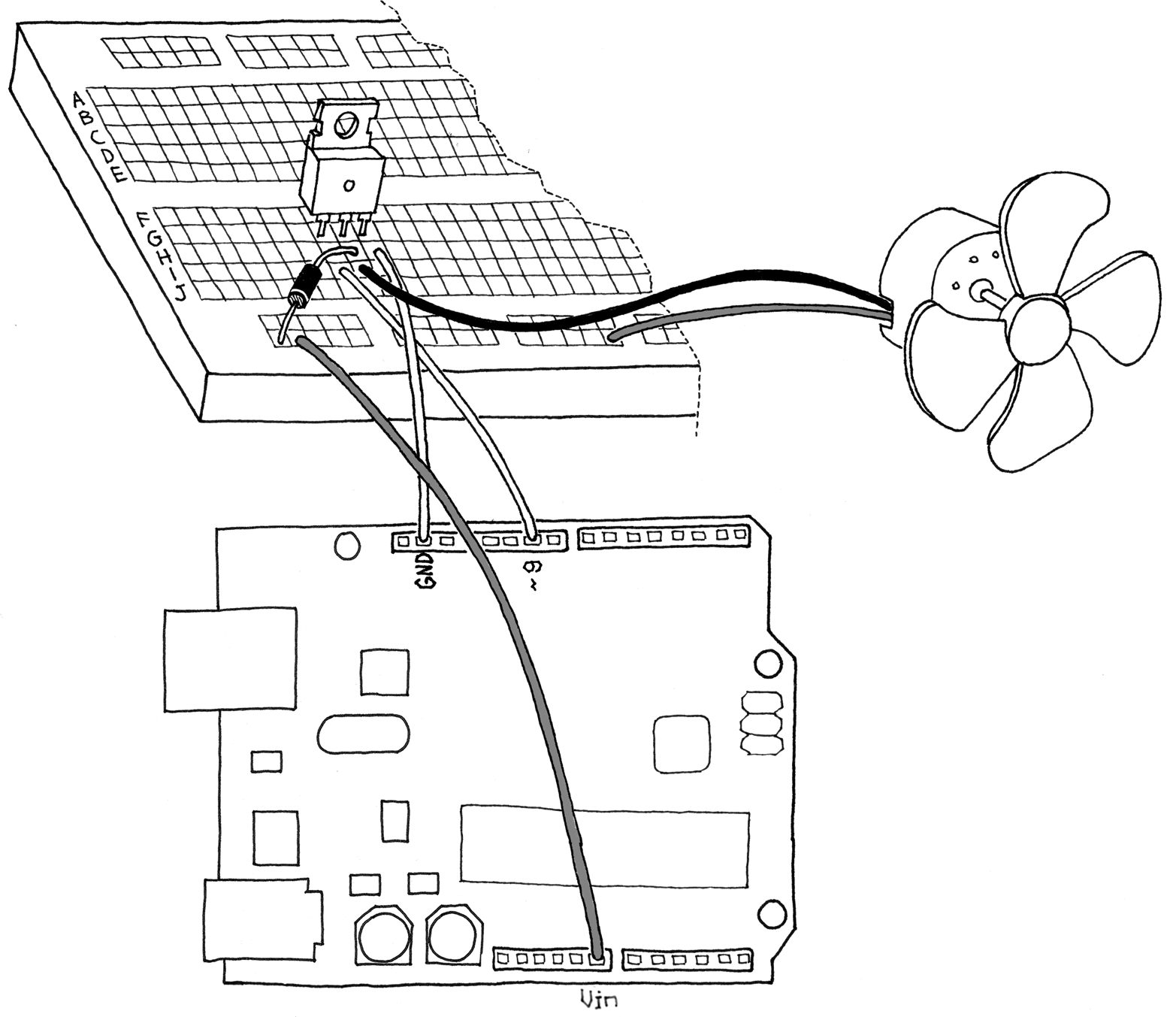
Figure 5-7. A motor circuit for Arduino
The Arduino Alphabet
In the preceding chapters, you learned the basics of Arduino and the fundamental building blocks available to you. Let’s go over what makes up the “Arduino Alphabet”:
- Digital output
-
We used it to control an LED but, with the proper circuit, it can be used to control motors, make sounds, and a lot more.
- Analogue output
-
This gives us the ability to control the brightness of the LED, not just turn it on or off. We can even control the speed of a motor with it.
- Digital input
-
This allows us to read the state of sensors that just say yes or no, like pushbuttons or tilt switches.
- Analogue input
-
We can read signals from sensors that have more information than just on or off, like a potentiometer that can tell where it’s been turned to, or a light sensor that can tell how much light is on it.
- Serial communication
-
This allows us to communicate with a computer and exchange data or simply monitor what’s going on with the sketch that’s running on the Arduino.