Chapter 4. Really Getting Started with Arduino
Now you’ll learn how to build and program an interactive device.
Anatomy of an Interactive Device
All of the objects we will build using Arduino follow a very simple pattern that we call the interactive device. The interactive device is an electronic circuit that is able to sense the environment by using sensors (electronic components that convert real-world measurements into electrical signals). The device processes the information it gets from the sensors with behaviour that’s described in the software. The device will then be able to interact with the world by using actuators, electronic components that can convert an electric signal into a physical action.
Sensors and Actuators
Sensors and actuators are electronic components that allow a piece of electronics to interact with the world.
As the microcontroller is a very simple computer, it can process only electric signals (a bit like the electric pulses that are sent between neurons in our brains). For it to sense light, temperature, or other physical quantities, it needs something that can convert them into electricity. In our body, for example, the eye converts light into signals that get sent to the brain using nerves. In electronics, we can use a simple device called a light-dependent resistor (LDR), also known as a photoresistor, that can measure the amount of light that hits it and report it as a signal that can be understood by the microcontroller.
Once the sensors have been read, the device has the information needed to decide how to react. The decision-making process is handled by the microcontroller, and the reaction is performed by actuators. In our bodies, for example, muscles receive electric signals from the brain and convert them into a movement. In the electronic world, these functions could be performed by a light or an electric motor.
In the following sections, you will learn how to read sensors of different types and control different kinds of actuators.
Blinking an LED
The LED blinking sketch is the first program that you should run to test whether your Arduino board is working and is configured correctly. It is also usually the very first programming exercise someone does when learning to program a microcontroller. A light-emitting diode (LED) is a small electronic component that’s a bit like a lightbulb, but is more efficient and requires a lower voltage to operate.
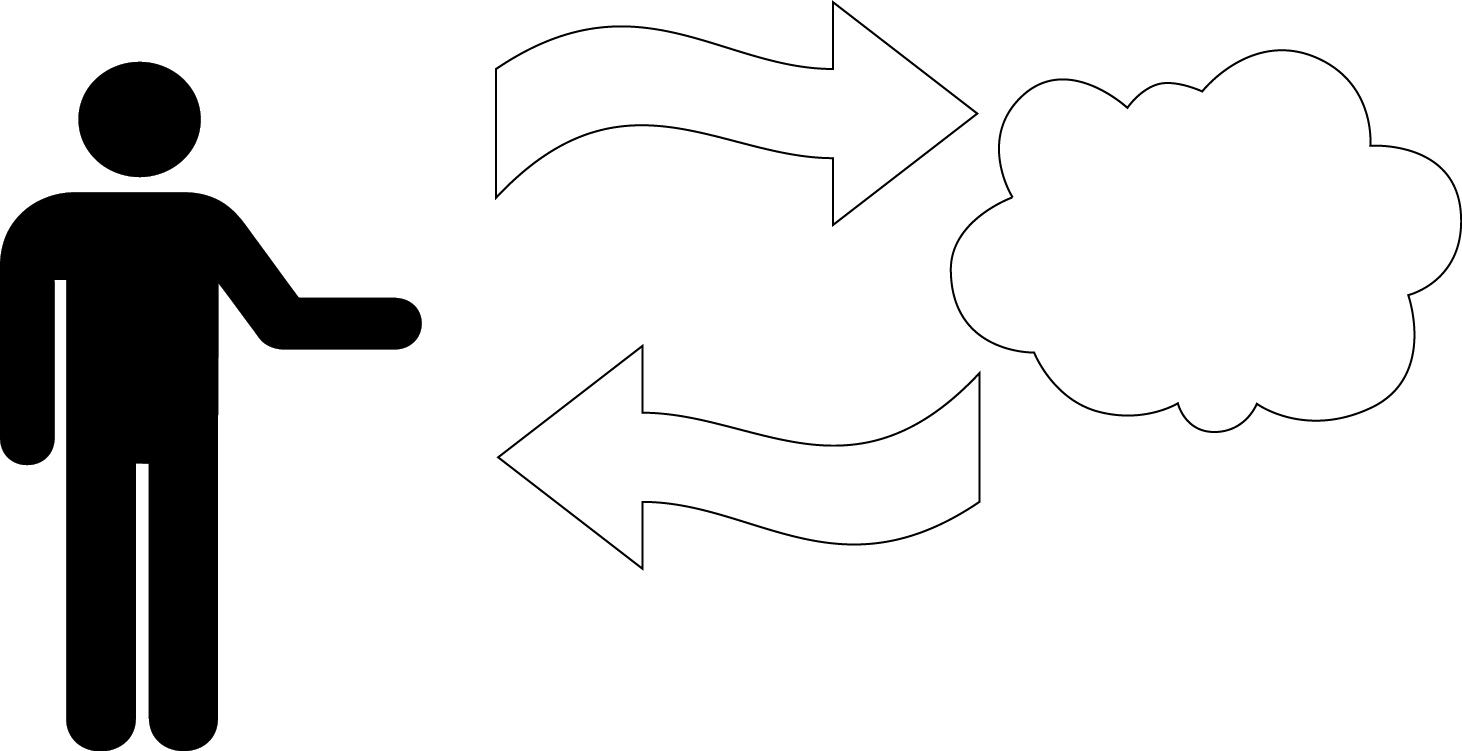
Your Arduino board comes with an LED preinstalled. It’s marked L on the board. This preinstalled LED is connected to pin number 13. Remember that number because we’ll need to use it later. You can also add your own LED1—connect it as shown in Figure 4-1. Note that it’s plugged into the connector hole that is labeled 13.
Note
If you intend to keep the LED lit for a long period of time, you should use a resistor as described in “Controlling Light with PWM”.
K indicates the cathode (negative), or shorter lead; A indicates the anode (positive), or longer lead.
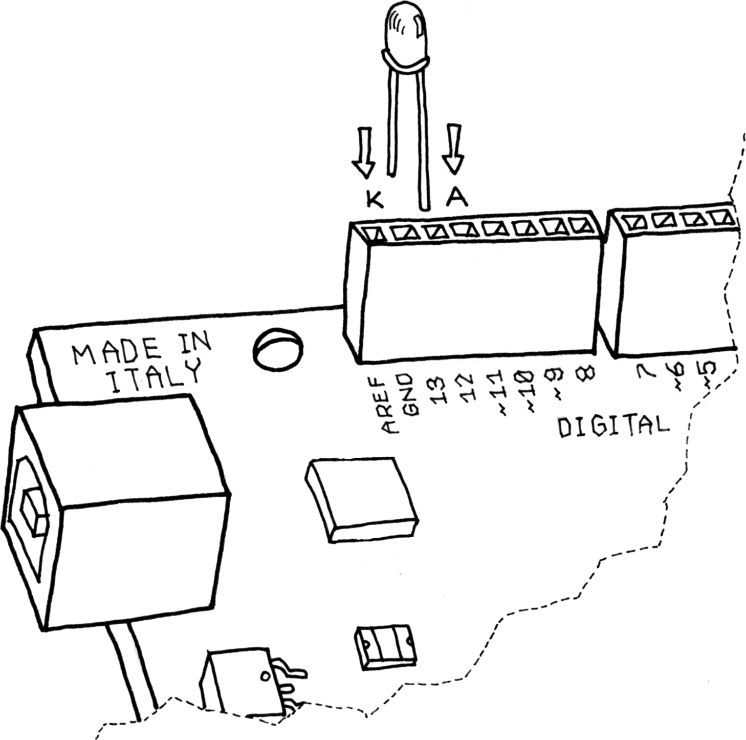
Figure 4-1. Connecting an LED to Arduino
Once the LED is connected, you need to tell Arduino what to do. This is done through code: a list of instructions that you give the microcontroller to make it do what you want. (The words code, program, and sketch are all terms that refer to this same list of instructions.)
On your computer, run the Arduino IDE (on the Mac, it should be in the Applications folder; on Windows, the shortcut will be either on your desktop or in the Start menu). Select File→New and you’ll be asked to choose a sketch folder name: this is where your Arduino sketch will be stored. Name it Blinking_LED and click OK. Then, type the following sketch (Example 4-1) into the Arduino sketch editor (the main window of the Arduino IDE). You can also download it from the example code link on the book’s catalog page.
You can also load this sketch simply by clicking File→Examples→01.Basics→Blink, but you’ll learn better if you type it in yourself. The built-in example might be slightly different but basically does exactly the same thing.
It should appear as shown in Figure 4-2.
Example 4-1. Blinking LED
// Blinking LEDconstintLED=13;// LED connected to// digital pin 13voidsetup(){pinMode(LED,OUTPUT);// sets the digital// pin as output}voidloop(){digitalWrite(LED,HIGH);// turns the LED ondelay(1000);// waits for a seconddigitalWrite(LED,LOW);// turns the LED offdelay(1000);// waits for a second}
Figure 4-2. The Arduino IDE with your first sketch loaded
Now that the code is in your IDE, you need to verify that it is correct. Click the Verify button (Figure 4-2 shows its location -- the check mark in the top left); if everything is correct, you’ll see the message “Done compiling” appear at the bottom of the Arduino IDE. This message means that the Arduino IDE has translated your sketch into an executable program that can be run by the board, a bit like an .exe file in Windows or an .app file on a Mac.
If you get an error, most likely you made a mistake typing in the code. Look at each line very carefully and check each and every character, especially symbols like parentheses, braces, semicolons, and commas. Make sure you’ve copied uppercase and lowercase faithfully, and that you’ve used the letter O and the number 0 correctly.
Once your code verifies correctly, you can upload it into the board by clicking the Upload button next to Verify (see Figure 4-2). This will tell the IDE to start the upload process, which first resets the Arduino board, forcing it to stop what it’s doing and listen for instructions coming from the USB port. The Arduino IDE will then send the sketch to the Arduino board, which will store the sketch in its permanent memory. Once the IDE has sent the entire sketch, the Arduino board will start running your sketch.
This happens fairly quickly. If you keep your eyes on the bottom of the Arduino IDE, you will see a few messages appear in the black area at the bottom of the window, and just above that area, you might see the message “Compiling,” then “Uploading,” and finally “Done uploading” to let you know the process has completed correctly.
There are two LEDs, marked RX and TX, on the Arduino board; these flash every time a byte is sent or received by the board. During the upload process, they keep flickering. This also happens very quickly, so unless you’re looking at your Arduino board at the right time, you might miss it.
If you don’t see the LEDs flicker, or if you get an error message instead of “Done uploading”, then there is a communication problem between your computer and Arduino. Make sure you’ve selected the right serial port (see Chapter 3) in the Tools→Serial Port menu. Also, check the Tools→Board menu to confirm that the correct model of Arduino is selected there.
If you are still having problems, check Chapter 11.
Once the code is in your Arduino board, it will stay there until you put another sketch on it. The sketch will survive if the board is reset or turned off, a bit like the data on your computer’s hard drive.
Assuming that the sketch has been uploaded correctly, you will see the LED L turn on for a second and then turn off for a second. If you installed a separate LED as shown back in Figure 4-1, that LED will blink too. What you have just written and run is a computer program, or sketch, as Arduino programs are called. Arduino, as we’ve mentioned before, is a small computer, and it can be programmed to do what you want. This is done by typing a series of instructions into the Arduino IDE, which then turns it into an executable for your Arduino board.
We’ll next show you how to understand the sketch. First of all, the Arduino executes the code sequentially from top to bottom, so the first line at the top is the first one read; then it moves down, a bit like how you might be reading this book, from the top of each page to the bottom.
Pass Me the Parmesan
Notice the presence of curly braces, which are used to group lines of code together. These are particularly useful when you want to give a name to a group of instructions. If you’re at dinner and you ask somebody, “Please pass me the Parmesan cheese,” this kicks off a series of actions that are summarised by the small phrase that you just said. As we’re humans, it all comes naturally, but all the individual tiny actions required to do this must be spelled out to the Arduino, because it’s not as powerful as our brain. So to group together a number of instructions, you stick a { before the block of code and a } after.
You can see that there are two blocks of code defined in this way here. Before each one of them are some strange words:
voidsetup()
This line gives a name to a block of code. If you were to write a list of instructions that teach Arduino how to pass the Parmesan, you would write void passTheParmesan() at the beginning of a block, and this block would become an instruction that you can call from anywhere in the Arduino code. These blocks are called functions. Now that you’ve created a function from this block of code, you can write passTheParmesan() anywhere in your sketch, and Arduino will jump to the passTheParmesan() function, execute those instructions, and then jump back to where it was and continue where it left off.
This points out something important about any Arduino program. Arduino can do only one thing at a time, one instruction at a time. As Arduino runs your program, line by line, it’s executing, or running, only that one line. When it jumps to a function, it executes the function, line by line, before returning to where it was. Arduino can’t run two sets of instructions at the same time.
Arduino Is Not for Quitters
Arduino always expects that you’ve created two functions: one called setup() and one called loop().
setup() is where you put all the code that you want to execute once at the beginning of your program, and loop() contains the core of your program, which is executed over and over again. This is done because Arduino is not like your regular computer—it cannot run multiple programs at the same time, and programs can’t quit. When you power up the board, the code runs; when you want to stop, you just turn it off.
Real Tinkerers Write Comments
Any text beginning with // is ignored by Arduino. These lines are comments, which are notes that you leave in the program for yourself, so that you can remember what you did when you wrote it, or for somebody else, so they can understand your code.
It is very common (we know this because we do it all the time) to write a piece of code, upload it onto the board, and say “OK—I’m never going to have to touch this sucker again!” only to realise six months later that you need to update the code or fix a bug. At this point, you open up the program, and if you haven’t included any comments in the original program, you’ll think, “Wow—what a mess! Where do I start?” As we move along, you’ll see some tricks for how to make your programs more readable and easier to maintain.
The Code, Step by Step
At first, you might consider this kind of explanation too unnecessary, a bit like when I was in school and I had to study Dante’s Divina Commedia (every Italian student has to go through that, as well as another book called I promessi sposi, or The Betrothed—oh, the nightmares). For each line of the poems, there were a hundred lines of commentary! However, the explanation will be much more useful here as you move on to writing your own programs.
—Massimo
// Blinking LEDA comment is a useful way for us to write little notes. The preceding title comment just reminds us that this program, Example 4-1, blinks an LED.
constintLED=13;// LED connected to// digital pin 13
const int means that LED is the name of an integer number that can’t be changed (i.e., a constant) whose value is set to 13. It’s like an automatic search-and-replace for your code; in this case, it’s telling Arduino to write the number 13 every time the word LED appears.
The reason we need the number 13 is that the preinstalled LED we mentioned earlier is attached to Arduino pin 13. A common convention is to use uppercase letters for constants.
voidsetup()
This line tells Arduino that the next block of code will be a function named setup().
{With this opening curly brace, a block of code begins.
pinMode(LED,OUTPUT);// sets the digital// pin as output
Finally, a really interesting instruction! pinMode() tells Arduino how to configure a certain pin. All of the Arduino pins can be used either as input or output, but we need to tell Arduino how we intend to use the pin.
In this case, we need an output pin to control our LED.
pinMode() is a function, and the words (or numbers) specified inside the parentheses are called its arguments. Arguments are whatever information a function needs in order to do its job.
The pinMode() function needs two arguments. The first argument tells pinMode() which pin we’re talking about, and the second argument tells pinMode() whether we want to use that pin as an input or output. INPUT and OUTPUT are predefined constants in the Arduino language.
Remember that the word LED is the name of the constant which was set to the number 13, which is the pin number to which the LED is attached. So, the first argument is LED, the name of the constant.
The second argument is OUTPUT, because when Arduino talks to an actuator such as an LED, it’s sending information out.
}This closing curly brace signifies the end of the setup() function.
voidloop(){
loop() is where you specify the main behaviour of your interactive device. It will be repeated over and over again until you remove power from the board.
digitalWrite(LED,HIGH);// turns the LED on
As the comment says, digitalWrite() is able to turn on (or off) any pin that has been configured as an output. Just as we saw with the pinMode() function, digitalWrite() expects two arguments, and just as we saw with the pinMode() function, the first argument tells digitalWrite() what pin we’re talking about, and just as we saw with the pinMode() function, we’ll use the constant name LED to refer to pin number 13, which is where the preinstalled LED is attached.
The second argument is different: in this case, the second argument tells digitalWrite() whether to set the voltage level to 0 V (LOW) or to 5 V (HIGH).
Imagine that every output pin is a tiny power socket, like the ones you have on the walls of your apartment. European ones are 230 V, American ones are 110 V, and Arduino works at a more modest 5 V. The magic here is when software can control hardware. When you write digitalWrite(LED, HIGH), it turns the output pin to 5 V, and if you connect an LED, it will light up. So at this point in your code, an instruction in software makes something happen in the physical world by controlling the flow of electricity to the pin. Turning on and off the pin will now let us translate these into something more visible for a human being; the LED is our actuator.
On the Arduino, HIGH means that the pin will be set to 5 V, while LOW means the pin will be set to 0 V.
You might wonder why we use HIGH and LOW instead of ON and OFF. It’s true that HIGH or LOW usually correspond to on and off, respectively, but this depends on how the pin is used. For example, an LED connected between 5V and a pin will turn on when that pin is LOW and turn off when the pin is HIGH. But for most cases you can just pretend that HIGH means ON and LOW means OFF.
delay(1000);// waits for a second
Although Arduino is much slower than your laptop, it’s still very fast. If we turned the LED on and then immediately turned it off, our eyes wouldn’t be able to see it. We need to keep the LED on for a while so that we can see it, and the way to do that is to tell Arduino to wait for a while before going to the next step. delay() basically makes the microcontroller sit there and do nothing for the amount of milliseconds that you pass as an argument. Milliseconds are thousandths of seconds; therefore, 1,000 milliseconds equals 1 second. So the LED stays on for 1 second here.
digitalWrite(LED,LOW);// turns the LED off
This instruction now turns off the LED that we previously turned on.
delay(1000);// waits for a second
Here, we delay for another second. The LED will be off for 1 second.
}This closing curly brace marks the end of the loop() function. When Arduino gets to this, it starts over again at the beginning of loop().
To sum up, this program does this:
-
Turns pin 13 into an output (just once at the beginning)
-
Enters a loop
-
Switches on the LED connected to pin 13
-
Waits for a second
-
Switches off the LED connected to pin 13
-
Waits for a second
-
Goes back to beginning of the loop
We hope that wasn’t too painful. If you didn’t understand everything, don’t feel discouraged. As we mentioned before, if you’re new to these concepts, it takes a while before they make sense. You’ll learn more about programming as you go through the later examples.
Before we move on to the next section, we want you to play with the code. For example, reduce the amount of delay, using different numbers for the on and off pulses so that you can see different blinking patterns. In particular, you should see what happens when you make the delays very small, but use different delays for on and off. There is a moment when something strange happens; this “something” will be very useful when you learn about pulse-width modulation in “Controlling Light with PWM”.
What We Will Be Building
I have always been fascinated by light and the ability to control different light sources through technology. I have been lucky enough to work on some interesting projects that involve controlling light and making it interact with people. Arduino is really good at this.
—Massimo
In this chapter, Chapter 5, and Chapter 6, we will be working on how to design interactive lamps, using Arduino as a way to learn the basics of how interactive devices are built. Remember, though, that Arduino doesn’t really understand, or care, what you connect to the output pins. Arduino just turns the pin HIGH or LOW, which could be controlling a light, or an electric motor, or your car engine.
In the next section, we’ll explain the basics of electricity in a way that would bore an engineer but won’t scare a new Arduino programmer.
What Is Electricity?
If you have done any plumbing at home, electronics won’t be a problem for you to understand. To understand how electricity and electric circuits work, the best way is to use something called the water analogy. Let’s take a simple device, like the battery-powered portable fan shown in Figure 4-3.
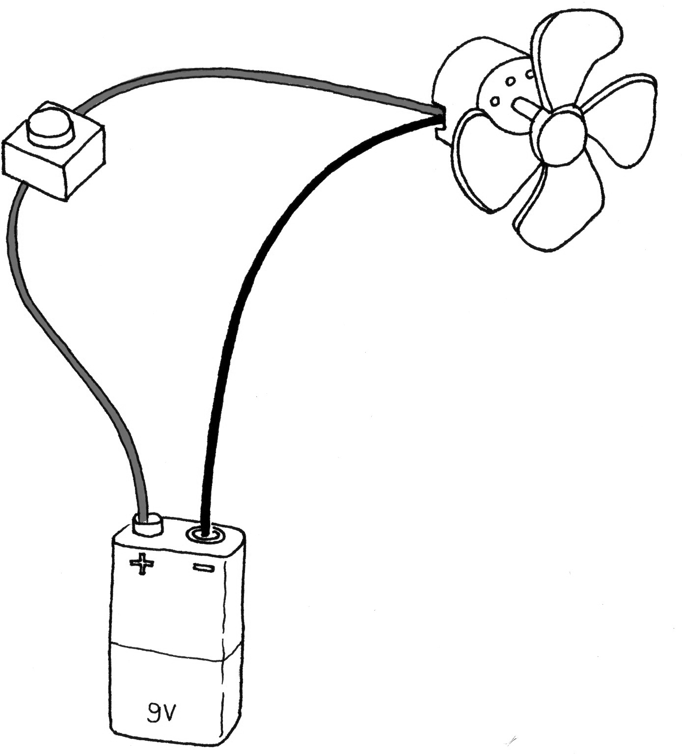
Figure 4-3. A portable fan
If you take a fan apart, you will see that it contains a battery, a couple of wires, and an electric motor, and that one of the wires going to the motor is interrupted by a switch. If you turn the switch on, the motor will start to spin, providing the necessary airflow to cool you down.
How does this work? Well, imagine that the battery is both a water reservoir and a pump, the switch is a tap, and the motor is one of those wheels that you see in watermills. When you open the tap, water flows from the pump and pushes the wheel into motion.
In this simple hydraulic system, shown in Figure 4-4, two factors are important: the pressure of the water (this is determined by the power of the pump) and the amount of water that will flow in the pipes (this depends on the size of the pipes and the resistance that the wheel will provide to the stream of water hitting it).
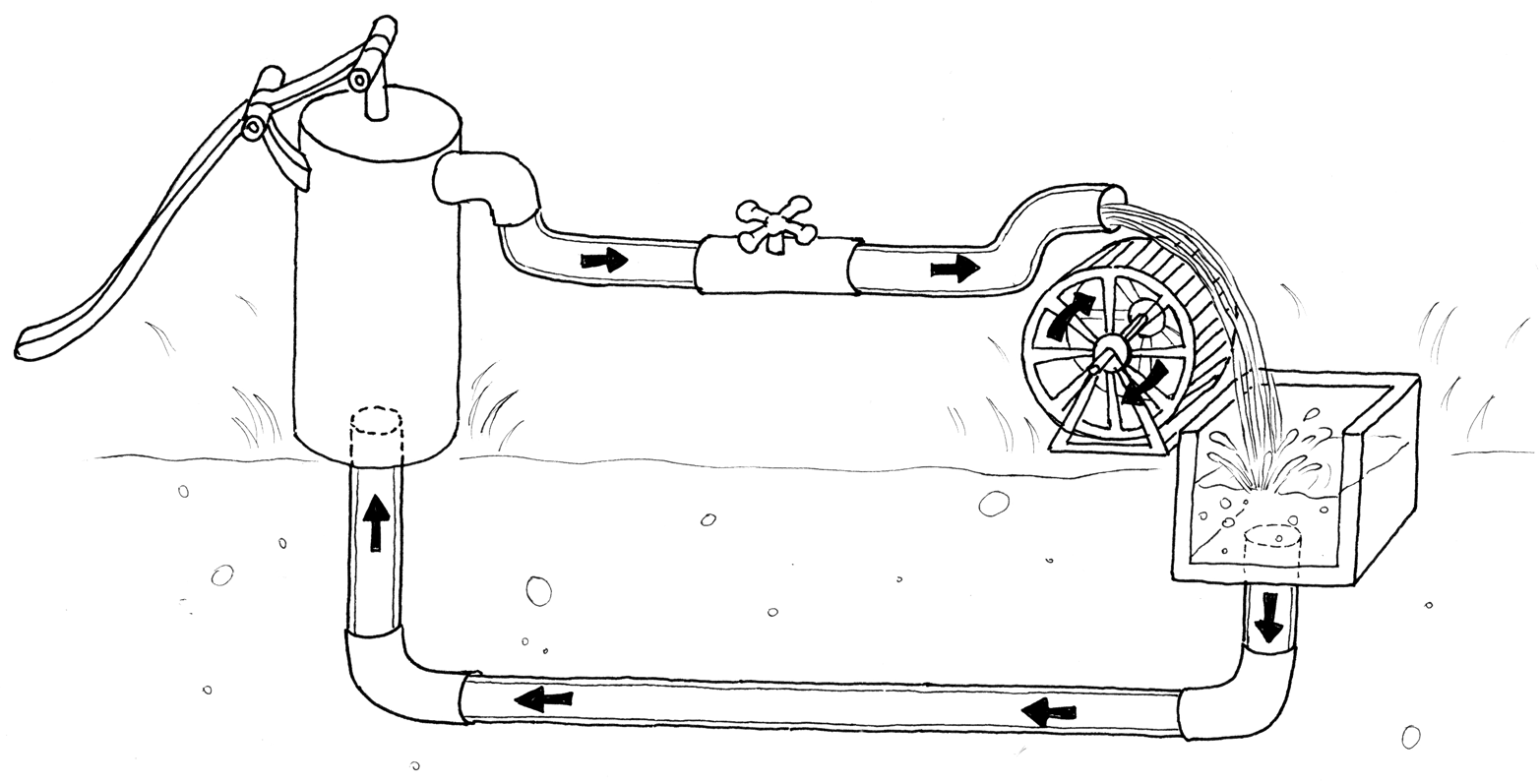
Figure 4-4. A hydraulic system
You’ll quickly realise that if you want the wheel to spin faster, you need to increase the size of the pipes (but this works only up to a point) and increase the pressure that the pump can achieve. Increasing the size of the pipes allows a greater flow of water to go through them; by making them bigger, you have effectively reduced the pipes’ resistance to the flow of water. This approach works up to a certain point, at which the wheel won’t spin any faster, because the pressure of the water is not strong enough. When you reach this point, you need the pump to be stronger. This method of speeding up the watermill can go on until the point when the wheel falls apart because the water flow is too strong for it and it is destroyed. Another thing you will notice is that as the wheel spins, the axle will heat up a little bit, because no matter how well you have mounted the wheel, the friction between the axle and the holes in which it is mounted will generate heat. It is important to understand that in a system like this, not all the energy you pump into the system will be converted into movement; some will be lost in a number of inefficiencies and will generally show up as heat emanating from some parts of the system.
So what are the important parts of the system? The pressure produced by the pump is one; the resistance that the pipes and wheel offer to the flow of water, and the actual flow of water (let’s say that this is represented by the number of litres of water that flow in one second) are the others.
Electricity works a bit like water. You have a kind of pump (any source of electricity, like a battery or a wall plug) that pushes electric charges (imagine them as “drops” of electricity) down pipes, which are represented by the wires. Various electrical devices are able to use these drops of electricity to produce heat (your grandma’s electric blanket), light (your bedroom lamp), sound (your stereo), movement (your fan), and much more.
When you read that a battery’s voltage is 9V, think of this voltage as the water pressure that can potentially be produced by this little “pump”. Voltage is measured in volts, named after Alessandro Volta, the inventor of the first battery.
Just as water pressure has an electric equivalent, the flow rate of water does too. This is called current, and is measured in amperes (after André-Marie Ampère, electromagnetism pioneer). The relationship between voltage and current can be illustrated by returning to the water wheel: a higher voltage (pressure) lets you spin a wheel faster; a higher flow rate (current) lets you spin a larger wheel.
Finally, the resistance opposing the flow of current over any path that it travels is called—you guessed it—resistance, and is measured in ohms (after the German physicist Georg Ohm). Herr Ohm was also responsible for formulating the most important law in electricity—and the only formula that you really need to remember. He was able to demonstrate that in a circuit, the voltage, the current, and the resistance are all related to each other, and in particular that the resistance of a circuit determines the amount of current that will flow through it, given a certain voltage supply.
It’s very intuitive, if you think about it. Take a 9 V battery and plug it into a simple circuit. While measuring current, you will find that the more resistors you add to the circuit, the less current will travel through it. Going back to the analogy of water flowing in pipes, given a certain pump, if we install a valve (which we can relate to a variable resistor in electricity), the more we close the valve—increasing resistance to water flow—the less water will flow through the pipes. Ohm summarised his law in these formulas:
R (resistance) = V (voltage) / I (current)
V = R * I
I = V / R
What’s important about this law is understanding it intuitively, and for this, we prefer the last version (I = V / R) because the current is something that results when you apply a certain voltage (the pressure) to a certain circuit (the resistance). The voltage exists whether or not it’s being used, and the resistance exists whether or not it’s being given electricity, but the current comes into existence only when these are put together.
Using a Pushbutton to Control the LED
Blinking an LED was easy, but we don’t think you would stay sane if your desk lamp were to continuously blink while you were trying to read a book. Therefore, you need to learn how to control it. In the previous example, the LED was your actuator, and the Arduino was controlling it. What’s missing to complete the picture is a sensor.
In this case, we’re going to use the simplest form of sensor available: a pushbutton switch.
If you were to take apart a pushbutton, you would see that it is a very simple device: two bits of metal kept apart by a spring, and a plastic cap that when pressed brings the two bits of metal into contact. When the bits of metal are apart, there is no circulation of current in the pushbutton (a bit like when a water valve is closed); when you press it, you make a connection.
All switches are basically just this: two (or more) pieces of metal that can be brought into contact with each other, allowing electricity to flow from one to the other, or separated, preventing the flow of electricity.
To monitor the state of a switch, there’s a new Arduino instruction that you’re going to learn: the digitalRead() function.
digitalRead() checks to see whether there is any voltage applied to the pin that you specify between parentheses, and returns a value of HIGH or LOW, depending on its findings. The other instructions that you’ve used so far haven’t returned any information—they just executed what we asked them to do. But that kind of function is a bit limited, because it will force you to stick with very predictable sequences of instructions, with no input from the outside world. With digitalRead(), you can “ask a question” of Arduino and receive an answer that can be stored in memory somewhere and used to make decisions immediately or later.
Build the circuit shown in Figure 4-5. To build this, you’ll need to obtain some parts2 (these will come in handy as you work on other projects as well):
- Solderless breadboard
- Precut jumper wire kit
- One 10 K ohm resistor
- Momentary tactile pushbutton switch
Note
Instead of buying precut jumper wire, you can also buy 22 AWG solid-core hookup wire in small spools and then cut and strip it yourself using wire cutters and wire strippers.
Note
GND on the Arduino board stands for ground. The word is historical, but in our case simply means the negative side of the power. We tend to use the words GND and ground interchangeably. You can think of it as the pipe that’s underground in the water analogy in Figure 4-4.
In most circuits, GND or ground is used very frequently. For this reason, your Arduino board has three pins labeled GND. They are all connected together, and it makes no difference which one you use.
The pin labeled 5V is the positive side of the power, and is always 5 volts higher than the ground.
Example 4-2 shows the code that we’ll be using to control the LED with our pushbutton.
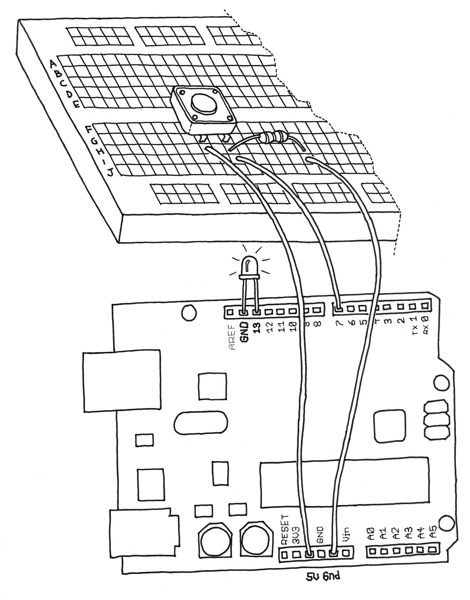
Figure 4-5. Hooking up a pushbutton
In Arduino, select File→New (if you have another sketch open, you may want to save it first). When Arduino asks you to name your new sketch folder, type PushButtonControl. Type the Example 4-2 code into Arduino (or download it from this book’s catalog page and paste it into the Arduino IDE). If everything is correct, the LED will light up when you press the button.
How Does This Work?
We have introduced two new concepts with this example program: functions that return the result of their work, and the if statement.
The if statement is possibly the most important instruction in a programming language, because it allows a computer (and remember, the Arduino is a small computer) to make decisions. After the if keyword, you have to write a “question” inside parentheses, and if the “answer”, or result, is true, the first block of code will be executed; otherwise, the block of code after else will be executed.
Notice that the == symbol is very different from the = symbol. The former is used when two entities are compared, and returns true or false; the latter assigns a value to a constant or a variable. Make sure that you use the correct one, because it is very easy to make that mistake and use just = , in which case your program will never work. We know, because after years of programming, we still make that mistake.
It’s important to realise that the switch is not connected directly to the LED. Your Arduino sketch inspects the switch, and then makes a decision as to whether to turn the LED on or off. The connection between the switch and the LED is really happening in your sketch.
Holding your finger on the button for as long as you need light is not practical. Although it would make you think about how much energy you’re wasting when you walk away from a lamp that you left on, we need to figure out how to make the on button “stick”.
One Circuit, a Thousand Behaviours
The great advantage of programmable electronics over classic electronics now becomes evident: I will show you how to implement many different “behaviours” using the same electronic circuit as in the previous section, just by changing the software.
As I’ve mentioned before, it’s not very practical to have to hold your finger on the button to have the light on. You therefore must implement some form of “memory”, in the form of a software mechanism that will remember when you have pressed the button and will keep the light on even after you have released it.
To do this, you’re going to use what is called a variable. (You have used one already, but we haven’t explained it.) A variable is a place in the Arduino memory where you can store data. Think of it like one of those sticky notes you use to remind yourself about something, such as a phone number: you take one, you write “Luisa 02 555 1212” on it, and you stick it to your computer monitor or your fridge. In the Arduino language, it’s equally simple: you just decide what type of data you want to store (a number or some text, for example), give it a name, and when you want to, you can store the data or retrieve it. For example:
intval=0;
int means that your variable will store an integer number, val is the name of the variable, and = 0 assigns it an initial value of zero.
A variable, as the name intimates, can be modified anywhere in your code, so that later on in your program, you could write:
val=112;
which reassigns a new value, 112, to your variable.
Note
Have you noticed that in Arduino, every instruction ends with a semicolon? This is done so the compiler (the part of Arduino that turns your sketch into a program that the microcontroller can run) knows your statement is finished and a new one is beginning. If you forget a semicolon where one is required, the compiler won’t be able to make sense of your sketch.
In the following program, the variable val stores the result of digitalRead(); whatever Arduino gets from the input ends up in the variable and will stay there until another line of code changes it. Notice that variables use a type of memory called RAM. It is quite fast, but when you turn off your board, all data stored in RAM is lost (which means that each variable is reset to its initial value when the board is powered up again). Your programs themselves are stored in flash memory—this is the same type used by your mobile phone to store phone numbers—which retains its content even when the board is off.
Let’s now use another variable to remember whether the LED has to stay on or off after we release the button. Example 4-3 is a first attempt at achieving that.
Now go test this code. You will notice that it works…somewhat. You’ll find that the light changes so rapidly that you can’t reliably set it on or off with a button press.
Let’s look at the interesting parts of the code: state is a variable that stores either 0 or 1 to remember whether the LED is on or off. After the button is released, we initialise it to 0 (LED off).
Later, we read the current state of the button, and if it’s pressed (val == HIGH), we change state from 0 to 1, or vice versa. We do this using a small trick, as state can be only either 1 or 0. The trick I use involves a small mathematical expression based on the idea that 1 – 0 is 1 and 1 – 1 is 0:
state=1-state;
The line may not make much sense in mathematics, but it does in programming. The symbol = means “assign the result of what’s after me to the variable name before me”—in this case, the new value of state is assigned the value of 1 minus the old value of state.
Later in the program, you can see that we use state to figure out whether the LED has to be on or off. As I mentioned, this leads to somewhat flaky results.
The results are flaky because of the way we read the button. Arduino is really fast; it executes its own internal instructions at a rate of 16 million per second—it could well be executing a few million lines of code per second. So this means that while your finger is pressing the button, Arduino might be reading the button’s position a few thousand times and changing state accordingly. So the results end up being unpredictable; it might be off when you wanted it on, or vice versa. As even a broken clock is right twice a day, the program might show the correct behaviour every once in a while, but much of the time it will be wrong.
How do you fix this? Well, you need to detect the exact moment when the button is pressed—that is the only moment that you have to change state. The way we like to do it is to store the value of val before we read a new one; this allows you to compare the current position of the button with the previous one and change state only when the button changes from LOW to HIGH.
Example 4-4 contains the code to do so.
You’ll notice something new in the if statement: there are two comparisons separated by a new symbol: &&. This symbol performs the logical AND operation, meaning that the compound statement is true only if both of the two simple statements are true.
Now test this code: you’re almost there!
You may have noticed that this approach is not entirely perfect, due to another issue with mechanical switches.
As we explained earlier, pushbuttons are just two bits of metal kept apart by a spring, that come into contact when you press the button. This might seem like the switch should be completely on when you press the button, but in fact what happens is the two pieces of metal bounce off each other, just like a ball bounces on the floor.
Although the bouncing is only for a very small distance and happens for a fraction of a second, it causes the switch to change between off and on a number of times until the bouncing stops, and Arduino is quick enough to catch this.
When the pushbutton is bouncing, the Arduino sees a very rapid sequence of on and off signals. There are many techniques developed to do debouncing, but in this simple piece of code, it’s usually enough to add a 10- to 50-millisecond delay when the code detects a transition. In other words, you just wait a bit for the bouncing to stop.
Example 4-5 is the final code.
One reader, Tami (Masaaki) Takamiya, wrote in with some extra code that may give you better debouncing:
if((val==LOW)&&(old_val==HIGH)){delay(10);}