As the game is an iOS game, we should work with caution when adding elements and code to save the game from any performance overhead, glitches, or crashes. Although the engine can run a game with the Light option on an iOS device, I always prefer to stay as far away as possible from using lights/directional lights in an iOS game, as a directional light source on mealtime would mean recalculating all the vertices. So, if the level has 10k vertices with two directional lights, it will be calculated as 30k vertices.
The best way to avoid using a light source for such a simple game like the brick breaking game is to build a special material that can emulate a light emission; this material is called an emissive material.
In your project panel, right-click in an empty space (perhaps inside the materials folder) and choose a material from the Basic Assets section. Give this material a name (which, in my case, is gameEmissiveMaterial) and then double-click to open the material editor.
As you can see, the material editor for a default new material is almost empty, apart from one big node that contains the material outputs with a black colored material. To start adding new nodes, you will need to right-click in an empty space of your editor grid and then either select a node or search for nodes by name; both ways work fine.
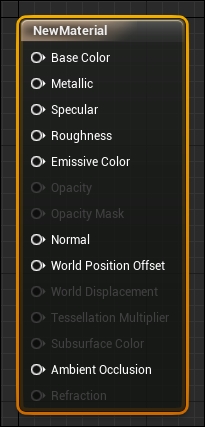
The emissive material is just a material with Color and Emissive Color; you can see these names in your output list, which means you will need to connect some sort of nodes or graphs to these two sockets of the material output.
Now, add the following three new nodes:
VectorParameter: This represents the color; you can pick a color by clicking on the color area on the left-hand panel of the screen or on the Default Value parameter.ScalarParameter: This represents a factor to scale the color of the material; you can set its Default Value to 2, which works fine for the game.Multiply: This will multiply two values (the color and the scalar) to give a value to be used for the emission.
With these three nodes in your graph, you might figure out how it works. The basic color has to be added to the base color output, and then the Multiply result of the base color and scalar will be added to the emissive color output of the material:
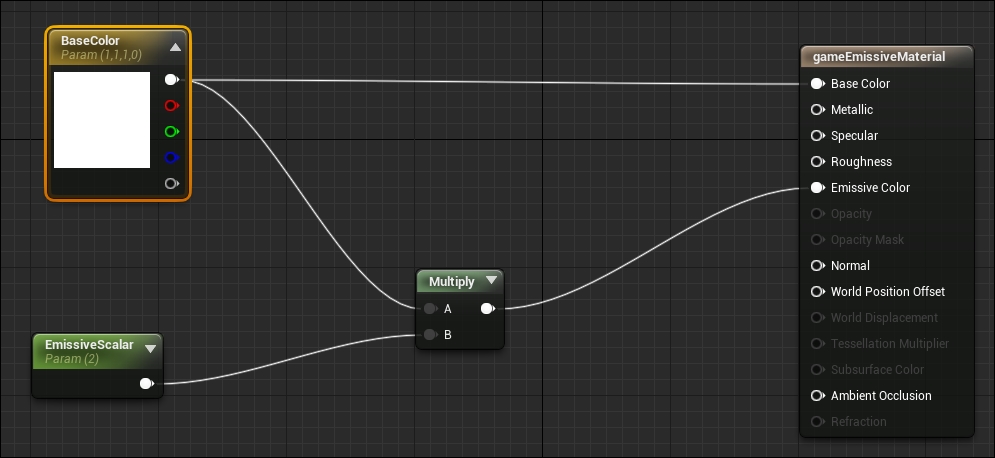
You can rename the nodes and give them special names, which will be useful later on. I named the VectorParameter node BaseColor and the Scalar node EmissiveScalar.
I prefer to call all the blueprints for this game actors as all of them will be based on a class in the engine core. This class usually represents any object with or without logic in the level. Although blueprints based on the actor class are not accepting input, you will learn a way to force any actor blueprint to get input events. This is the reason for picking the actor class as a general class for the course of this book. In this section, you will build the different blueprints for the game and add components for each one of them. Later on, in another section, you will build the logic and graphs. As I always say, building and setting all the components and the default values should be the first thing you do in any game, and then adding the logic should follow. Do not work on both simultaneously!
The layout blueprint should include the bricks that the players are going to break, the camera that renders the level, and the walls that the ball is going to collide with.
Start making it by adding an Actor blueprint in your project directory. Name it levelLayout and double-click on it to open the blueprint editor.
The blueprint editor, by default, contains the following three subeditors inside it; you can navigate between them via the buttons in the top-right corner:
- Defaults: This is used to set the default values of the blueprint class type
- Components: This is used to add different components to build and structure the blueprint
- Graph: This is where we will add scripting logic

The majority of the time, you will be working with the components and graph editors only, as the default editor's default values always work the best:
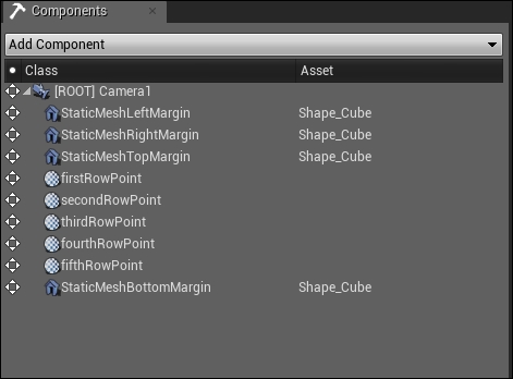
Open the component graph and start adding these components:
- Camera: This will be the component that renders the game. As you can see in the preceding screenshot, I added one component and left its name as Camera1. It was set as ROOT of the blueprint; it holds all the other components as children underneath its hierarchy.
- Changed Values: The only value you need to change in the camera component is Projection Mode. You need to set it to Orthographic, as it will be rendered as a 2D game, and keep Ortho Width as 512, as it will make the screen show all the content in a good size. Feel free to use different values based on the content of your level design.
- Static Mesh: To be able to add meshes as boundaries or triggering areas to collide with the ball, you will need to add cubes to work as collision walls, perhaps hidden walls. The best way to add this is by adding four static meshes and aligning and moving them to build them as a scene stage. Renaming all of them is also a good way to go. To be able to distinguish between them, you can name them as I named them: StaticMeshLeftMargin, StaticMeshRightMargin, StaticMeshTopMargin, and StaticMeshBottomMargin. The first three are the left, right, and top margins; they will be working as collision walls to force the ball to bounce in different directions. However, the bottom one will work as a trigger area to restart the level when the ball passes through it.

- For the walls, you need to add the Wall tag for the first three meshes in the Component Tags options area, and for the bottom trigger, you need to add another tag; something like deathTrigger works fine. These tags will be used by the gameplay logic to detect whether the ball hits a wall and you need to play a sound or whether it hits a death area and you need to restart the level.


- In the Collision section for each static mesh, you need to set both Simulation Generates Hit Events and Generate Overlap Events to True. Also, for Collision Preset, you can select Block All, as this will create solid walls to block any other object from passing:

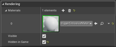
- Finally, from the Rendering options section, you need to select the emissive material we have made to be able to see those static meshes, and you need to mark Hidden in Game as True to hide those objects. Keep in mind that you can keep those objects in the game for debugging reasons, and when you are sure that they are in the correct place, you can move to this option again and remark it as True.
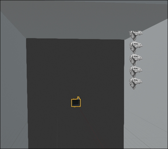
- Billboard: For now, you can think about the billboard component as a point in space with a representation icon, and this is how it is mostly used inside UE4 as the engine does not support an independent transform component yet. However, billboards have always been used to show the contents that always face the camera, such as particles, text, or any other thing you need to always get rendered from the same angle. As the game will be generating the blocks/bricks during the gameplay, you will need to have some points to define where to build or to start building those bricks. You can add five billboard points, rename them, and rearrange them to look like a column. You don't have to change any values for them, as you will be using their position in space values only! I named those five points as firstRowPoint, SecondRowPoint, thirdRowPoint, fourthRowPoint, and fifthRowPoint.
Start making the ball blueprint by adding an Actor blueprint in your project directory. Name it Ball and double-click on it to open the blueprint editor. Then, navigate to the Components subeditor if you are not ready. Start adding the following components to the blueprint:
- The sphere will work as the collision surface for the Ball blueprint. So, for this reason, you will need to set its Collision option to Simulation Generates Hit Events and Generate Overlap Events to True. Also, set the Collision Preset option to Block All to act in a manner similar to the walls from the layout blueprint. You need to set the Sphere Radius option from the Shape section to 26.0 so that it is of a good size that fits the screen's overall size.

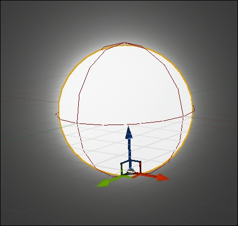
- The process for adding static meshes is the same as you did earlier, but this time, you will need to select a sphere mesh from the standard assets that came with the project. You will also need to set its material to the project default material you made earlier in this chapter. Also, after selecting it, you might need to adjust its Scale to 0.5 in all three axes to fit the collision sphere size. Feel free to move the static mesh component on the x, y, and z axes till it fits the collision surface.
- The projectile movement component is the most important one for the Ball blueprint, or perhaps it is the most important one throughout this chapter, as it is the one responsible for the ball movement and velocity and for its physics behaviors. After adding the components, you will need to make some tweaks to it to allow it to give the behavior that matches the game. Keep in mind that any small amount of change in values or variables will lead you to have a completely different behavior, so feel free to play through the values and test them to get some crazy ideas about what you can achieve and what you can get.
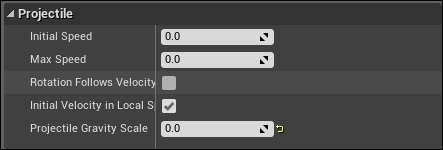
- For changed values, you need to set Projectile Gravity Scale to 0.0 from within the Projectile options; this will allow the ball to fly in the air without a gravity force to bring it down (or any other direction for a custom gravity).
- For Projectile Bounces, you will need to mark Should Bounce as True. In this case, the projectile physics will be forced to keep bouncing with the amount of bounciness you set. As you want the ball to keep bouncing over the walls, you need to set the value to 1.0 to give it full bounciness power:

- From the Velocity section, you will need to enter a velocity for the ball to start using when the game runs; otherwise, the ball will never move. As you want the first bounce of the ball to be towards the blocks, you need to set the Z value to a high number, such as 300, and give it more level design sense. It shouldn't bounce in a vertical line, so it is better to give some force on the horizontal axis Y as well as move the ball in a diagonal direction. So, let's add 300 into Y as well.

Start making the platform blueprint by adding an Actor blueprint in your project directory. Name it platform and double-click on it to open the blueprint editor. Then, navigate to the Components subeditor if you are not there already. You will add only one component, and it will work for everything. You want to add a Static Mesh component, but this time, you will be selecting the Pipe mesh; you can select whatever you want, but the pipe works the best.
Don't forget to set its material to be the same emissive material as we used earlier to be able to see it in the game view, and set its Collision option to Simulation Generates Hit Events and Generate Overlap Events to True. Also, Collision Preset should be set to Block All to act in the same manner as the walls from the layout blueprint.
Now, as all the blueprints have been set up with their components, it's time to start adding the gameplay logic/scripting. However, to be able to see the result of what you are going to build, you first need to drag and drop the three blueprints inside your scene and organize them to look like an actual level.
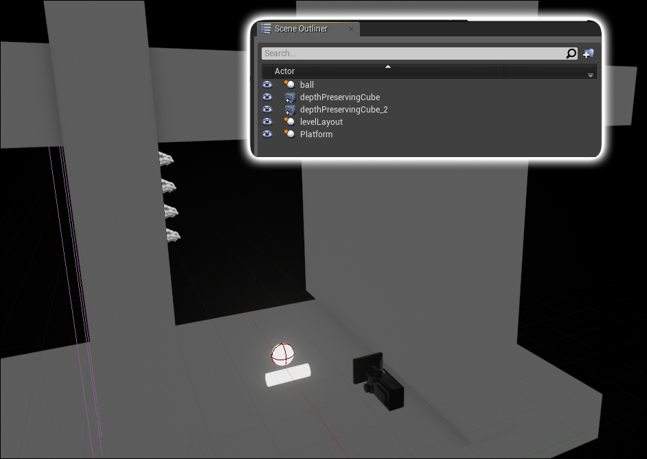
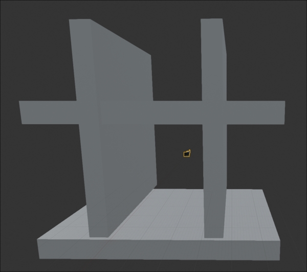
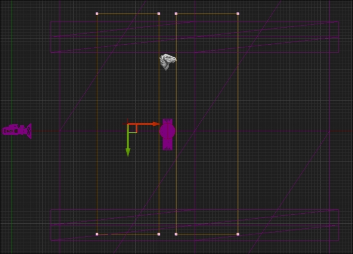
As the engine is a 3D engine and there is no support yet for 2D physics, you might notice that I added two extra objects to the scene (giant cubes), which I named depthPreservingCube and depthPreservingCube2. These objects are here basically to prevent the ball from moving in the depth axis, which is X in Unreal Editor. This is how both the new preserving cubes look from a top view:
One general step that you will perform for all blueprints is to set the dynamic material for them. As you know, you made only one material and applied it to the platform and to the ball. However, you also want both to look different during the gameplay. Changing the material color right now will change both objects' visibility. However, changing it during the gameplay via the construction script and the dynamic material instances feature will allow you to have many colors for many different objects, but they will still share the same material.
So, in this step, you will make the platform blueprint and the ball blueprint. I'll explain how to make it for the ball, and you will perform the same steps to make it for the platform. Select the ball blueprint first and double-click to open the editor; then, this time navigate to the subeditor graphs to start working with the nodes.
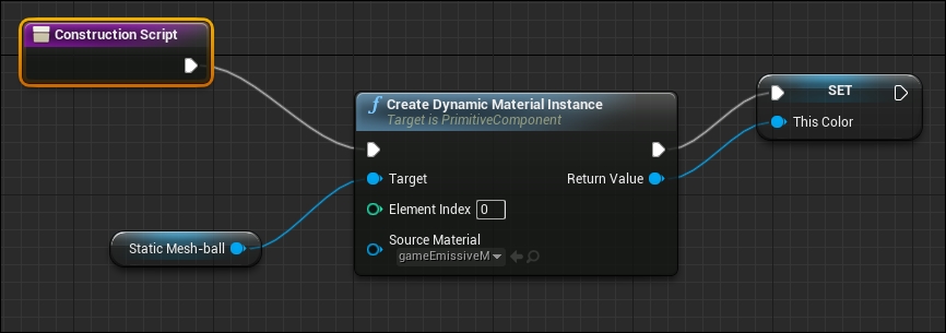
You will see that there are two major tabs inside the graph; one of them is named Construction Script. This unique tab is responsible for the construction of the blueprint itself. Open the Construction Script tab that always has a Construction Script node by default; then, drag and drop the StaticMesh component of the ball from the panel on the left-hand side. This will cause you to have a small context menu that has only two options: Get and Set. Select Get, and this will add a reference to the static mesh.
Now, drag a line from Construction Script, leave it in an empty space, add a Create Dynamic Material Instance node from the context menu, and set its Source Material option to the material we want to instance (which is the emissive material). However, keep in mind that if you are using a later version, Epic introduces a more easy way to access the Create Dynamic Material Instance node by just dragging a line from Static Mesh-ball inside Graph, and not Construction Script.
Now, connect the static mesh to be the target and drag a line out of Return Value of the Create Dynamic Material Instance node. From the context menu, select the first option, which is Promote to a Variable; this will add a variable to the left-panel list. Feel free to give it a name you can recognize, which, in my case, is thisColor. Now, the whole thing should look like this:
Now that you've created the dynamic material instance, you need to set the new color for it. To do this, you need to go back to the event graph and start adding the logic for it. I'll add it to the ball also, and you need to apply it again in Event Graph of the platform blueprint.
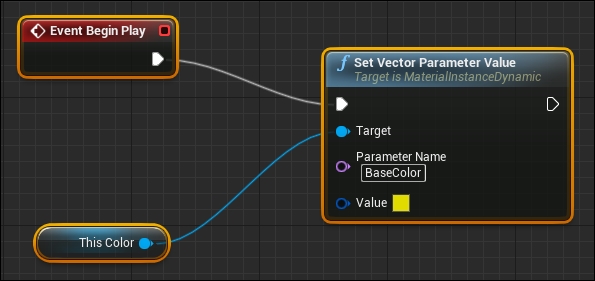
Add an Event Begin Play node, which is responsible for the execution of some procedurals when the game starts. Drag a wire out of it and select the Set Vector Parameter Value node that is responsible for setting the value for the material.
Now, add a reference for the thisColor variable and connect it to Target of the Set Vector Parameter Value node. Last but not least, enter Parameter name that you used to build the material, which, in my case, is BaseColor.
Finally, set Value to a color you like; I picked yellow for the ball. Which color would you like to pick?
Before you start working with this section, you need to make several copies of the material we made earlier and give each one its own color. I made six different ones to give a variation of six colors to the blocks.
The scripts here will be responsible for creating the blocks, changing their colors, and finally, setting the game view to the current camera. To serve this goal, you need to add several variables with several types. Here are some variables:
- numberOfColumns: This is an integer variable that has a default value of six, which is the total number of columns per row.
- currentProgressBlockPosition: This is a vector type variable to hold the position of the last created block. It is very important because you are going to add blocks one after the other, so you want to define the position of the last block and then add spacing to it.
- aBlockMaterial: This is the material that will be applied to a specific block.
- materialRandomIndex: This is a random integer value to be used for procedural selected colors for each block.
To make things more organized, I managed to make several custom events. You can think about them as a set of functions; each one has a block of procedurals to execute:
- Initialize The Blocks: This Custom Event node has a set of
forloops that are working one by one on initializing the target blocks when the game starts. Each loop cycles six times from Index 0 to the number of columns index. When it is finished, it runs the next loop. Each loop body is a custom function itself, and they all run the same set of procedurals, except that they use a different row.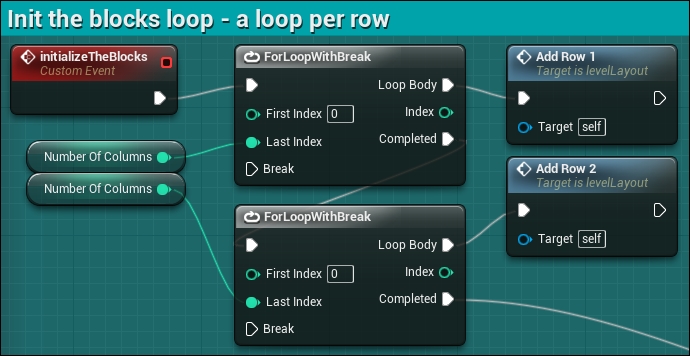
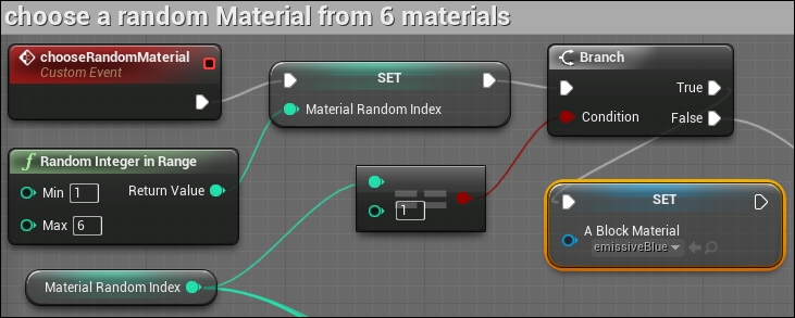
- chooseRandomMaterial: This custom event handles the process of picking a random material to be applied to in the process of creation. It works by setting a random value between 1 and 6 to the materialRandomIndex variable, and depending on the selected value, the aBlockMaterial variable will be set to a different material. This aBlockMaterial variable is the one that will be used to set the material of each created block in each iteration of the loop for each row.
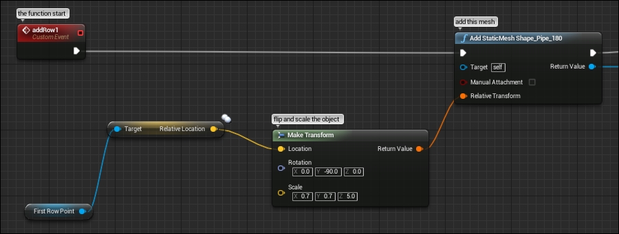
- addRowX: I named this X here, but in fact, there are five functions to add the rows; they are addRow1, addRow2, addRow3, addRow4, and addRow5. All of them are responsible for adding rows; the main difference is the start point of adding the row; each one of them uses a different billboard transform, starting from firstRowPoint and ending with fifthRowPoint. You need to connect your first node as Add Static Mesh and set its properties as any other static mesh. You need to set its material to the emissive one. Set Static Mesh to Shape_Pipe_180, give it a brickPiece tag, and set its Collision options to Simulation Generates Hit Events and Generate Overlap Events to True. Also, Collision Preset has to be set to Block All to act in the same manner as the walls from the layout blueprint and receive the hit events, which will be the core of the ball detection. This created mesh will need a transform point to be instantiated in its cords. This is where you will need to pick the row point transform reference (depending on your row, you will select the point number), add it to a Make Transform node, and finally, set the new transform Y Rotation to -90 and its XYZ scale to 0.7, 0.7, 0.5 to fit the correct size and flip the block to have a better convex look.
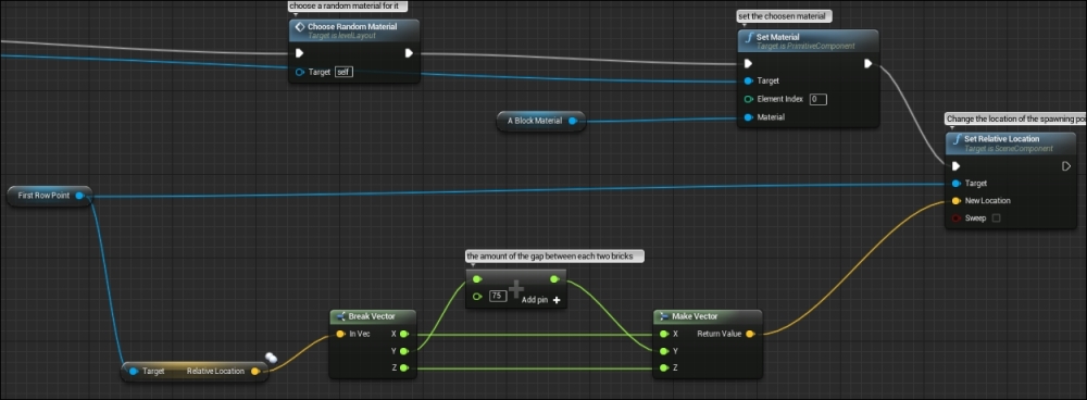
This second part of the addRow event should use the ChooseRandomMaterial custom event that you already made to select a material from among six random ones. Then, you can execute SetMaterial, make its Target the same mesh that was created via Add Static Mesh, and set its Material to aBlockMaterial; the material changes every time the chooseRandomMaterial event gets called.
Finally, you can use SetRelativeLocation of the billboard point that is responsible for that row to another position on the y axis, using the Make Vector and Add Int(+) nodes to add 75 units every time as a spacing between every two created blocks:
Now, if you check the project files, you will find that the only difference is that there are five functions called addRow, and each of them uses a different billboard as a starting point to add the blocks. Now, if you run the version you made or the one within the project files, you will be able to see the generated blocks, and each time you stop and run the game, you will get a completely different color variation of the blocks.
There is one last thing to completely finish this blueprint. As you might have noticed, this blueprint contains the camera in its components. This means it should be the one that holds the functionality of setting this camera to be the rendering camera. So, in Even Begin Play, this functionality will be fired when the level starts. You need to connect the the Set View Target With Blend node that will set the camera to the Target camera, and you need to connect Get Player Controller (player 0 is the player number 1) to the Target socket. This blueprint refers to New View Target. Finally, you need to call the initializeTheBlocks custom event, which will call all the other functions.

Congratulations! Now you have built your first functional and complex blueprint that contains the main and important functionalities everyone must use in any game. Also, you got the trick of how you can randomly generate or change things such as the color of the blocks to make the levels feel different every time.
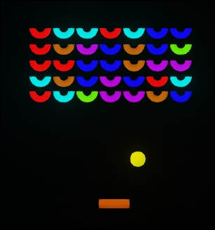
The main event node that will be used in the ball graph is Event Hit, which will be fired automatically every time the ball collider hits another collider. If you still remember, while creating the platform, walls, and blocks, we used to add tags for every static mesh to define them. Those names are used now. Using a node called Component Has Tag, we can compare the object component that the ball has hit with the value of the Component Has Tag node, and then, we either get a positive or negative result. So, this is how it should work:
- Whenever the ball gets hit with another collider, check whether it is a brickPiece tagged component. If this is true, then disable the collision of the brick piece via the Set Collision Enabled node and set it to No Collision to stop responding to any other collisions. Then, hide the brick mesh using the Set Visibility node and keep the New Visibility option unmarked, which means that it will be hidden. Then, play a sound effect of the hit to make it a more dynamic gameplay. You can play sound in many different ways, but let's use the Play Sound at Location node now, use the location of the ball itself, and use the hitBrick sound effect from the Audio folder by assigning it to the Sound slot of the Play Sound at Location node. Finally, reset the velocity of the ball using the Set Velocity node referenced by the Projectile Movement component and set it to XYZ 300, 0, 300:

- If it wasn't a brickPiece tag, then let's check whether it is Component Has Tag of Wall. If this is the case, then let's use Play Sound at Location, use the location of the ball itself, and use the hitBlockingWall sound effect from the Audio folder by assigning it to the Sound slot of the Play Sound at Location node:

- If it wasn't tagged with Wall, then check whether it is finally tagged with deathTrigger. If this is the case, then the player has missed it, and the ball is not below the platform. So, you can use the Open Level node to load the level again and assign the level name as mainLevel (or any other level you want to load) to the Level Name slot:

The platform blueprint will be the one that receives the input from the player. As you learned in Chapter 2, Methods and Tools to Create Your Games, it is better to set Use Mouse For Touch in Project settings so you can write one logic and it works for both mouse input in the editor and for the touch input on the device. However, as you might remember, all the blueprints are based on an Actor.h class; this means, by default, they will not accept any input, and any scripting-based input will be ignored and will not give any result. So, you just need to define the player input to make the blueprint able to receive those events from the mouse, touch, or any other available input device. To do this, there are two ways, and I always like to use both these ways:
- Enable input node: I assume that you've already added the scripting nodes inside Event graph to set the dynamic material color via Set Vector Parameter Value. This means you already have an Event Begin Play node, so you need to connect its network to another node called Enable Input; this node is responsible for forcing the current blueprint to accept input events. Finally, you can set its Player Controller value to a Get Player Controller node and leave Player Index as 0 for the player number 1:

- Autoreceive input option: By selecting the platform blueprint instance that you've dropped inside the scene from the Scene Outliner, you will see that it has many options in the Details panel on the right-hand side. By changing the Auto Receive Input option to Player 0 under the Input option, this will have the same effect as the previous solution:
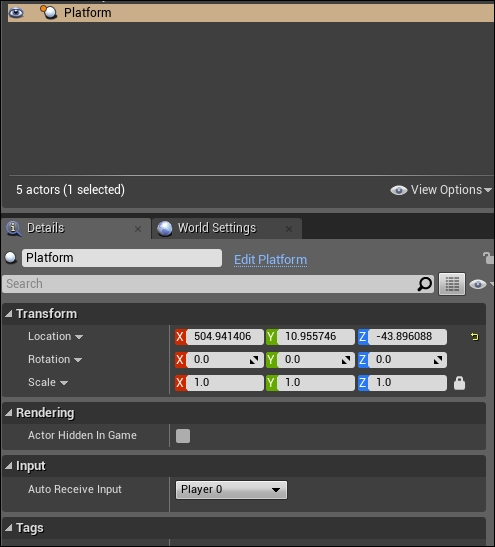
Now, we can build the logic for the platform movement, and anything that is built can be tested directly in the editor or on the device. I prefer to break the logic into two pieces, and this will make it easier than it looks like for you:
- Get the touch state: In this phase, you will use the Input Touch event that can be executed when a touch gets pressed or released. So based on the touch state, you will check via a Branch node whether the state is True or False. Your condition for this node should be Touch 1 index, as the game will not need more than one touch. Based on the state, I would like to set a custom Boolean variable named Touched and set its value to match the touch state. Then, you can add a Gate node to control the execution of the following procedurals based on the touch state (Pressed or Released) by connecting the two cases with the Open gate and the Close gate execution sockets. Finally, you can set the actor location and set it to use the Self actor as its target (which is the
platformactor/blueprint) to change the platform location based on touches. Defining the New Location value is the next chunk of the logic: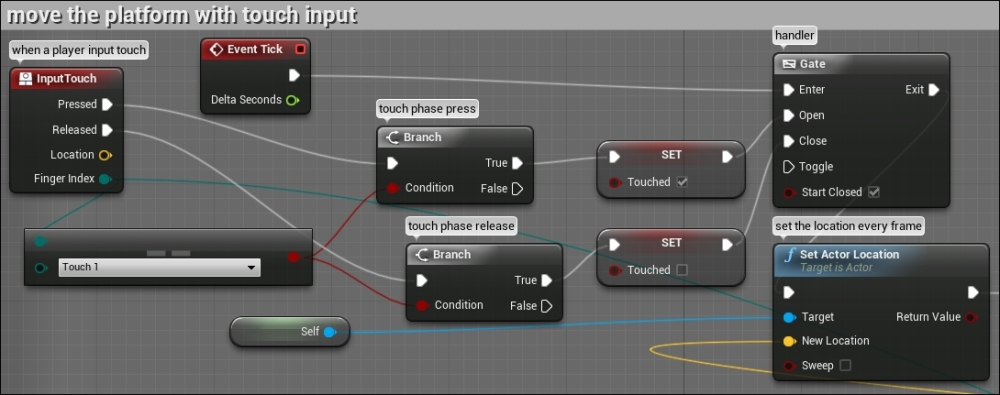
- Actor location: Using a Make Vector node, you can construct a new point position in the world made of X, Y, and Z coordinates. As the y axis will be the horizontal position, which will be based on the player's touch, only this needs to be changed over time. However, the X and Z positions will stay the same all the time, as the platform will never move vertically or in depth. The new vector position will be based on the touch phase. If the player is pressing, then the position should be matching the touch input position. However, if the players are not pressing, then the position should be the same as the last point the player had pressed. I managed to make a float variable named horizontalAxis; this variable will hold the correct Y position to be added to the Make Vector node. If the player is pressing the screen, then you need to get the finger press position by returning Impact Point by Break Hit Result via a Get Hit Result Under Finger By Channel node from the current active player. However, if the player is not touching the screen, then the horizontalAxis variable should stay the same as the last-know location for the Self actor. Then, it will set as it is into the Make Vector Y position value:
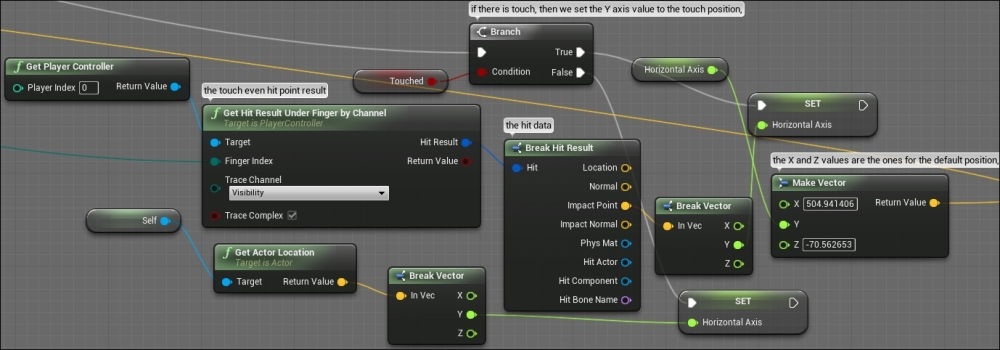
Now, you can save and build all the blueprints. Don't hesitate now or any time during the process of building the game logic to build or launch the game into a real device to check where you are.
The best way to learn more about the nodes and those minor changes is by building all the time into the divide and changing some values every time.

