Launch files for TurtleBot will create ROS nodes either remotely on the TurtleBot netbook (via SSH to TurtleBot) or locally on the remote computer. As a general rule, the launch files (and nodes) that handle the GUI and visualization processing should run on the remote computer while the minimal launch and camera drivers should run on the TurtleBot netbook or SBC. Note that we will specify when to SSH to TurtleBot for a ROS command or omit the SSH for using a ROS command on the remote computer.
TurtleBot can autonomously drive around its environment if a map is made of the environment. The 3D sensor is used to create a 2D map of the room as the TurtleBot is driven around either by a joystick, keyboard, or any other method of teleoperation.
Since we are using the Kobuki base, calibration of the gyro inside the base is not necessary. If you are using the Create base, make sure that you perform the gyro calibration procedure in the TurtleBot ROS wiki at http://wiki.ros.org/turtlebot_calibration/Tutorials/Calibrate%20Odometry%20and%20Gyro before you begin with the mapping operation.
The core terms that are used in TurtleBot navigation are as follows:
- Odometry: Data gathered from moving sensors is used to estimate the change in a robot's position over time. This data is used to estimate the current position of the robot relative to its starting location.
- Map: For TurtleBot, a map is a 2D representation of an environment encoded with occupancy data.
- Occupancy Grid Map (OGM): An OGM is a map generated from the 3D sensor measurement data and the known pose of the robot. The environment is divided into an evenly spaced grid in which the presence of obstacles is identified as a probabilistic value in each cell on the grid.
- Localization: Localization determines the present position of the robot with respect to a known map. The robot uses features in the map to determine where its current position is on the map.
The following steps are fairly complex and will require the use of four or five terminal windows. Be conscious of which commands are on TurtleBot (requiring SSH from the remote computer) and those that are on the remote computer (not requiring SSH). In each terminal window, enter the commands following the $ prompt:
- Terminal window 1: Minimal launch of TurtleBot:
$ ssh <username>@<TurtleBot's IP Address>
$ roslaunch turtlebot_bringup minimal.launch
These commands are the now familiar process of setting the many arguments and parameters and launching nodes for the TurtleBot mobile base functionality.
- Terminal window 2: Launch the gmapping operation as follows:
$ ssh <username>@<TurtleBot's IP Address>
$ roslaunch turtlebot_navigation gmapping_demo.launch
Look for the following text on your window:
odom received!The
gmapping_demolaunch file launches the3dsensor.launchfile, specifying turning off thergb_processing,depth_registration, anddepth_processingmodules. This leaves the modules forir_processing,disparity_processing,disparity_registered_processing, andscan_processing. The.xmlfiles forgmapping.launchandmove_base.launchare also invoked. Thegmapping.launch.xmlfile launches theslam_gmappingnode and sets multiple parameters in the.xmlfile. Themove_base.launch.xmlfile launches themove_basenode and also starts the nodes forvelocity_smootherandsafety_controller. A more complete description of this processing is provided in the following How does TurtleBot accomplish this mapping task? section. - Terminal window 3: View navigation on rviz by running the following command:
$ roslaunch turtlebot_rviz_launchers view_navigation.launchRviz should come up in the TopDownOrtho view identified in the Views panel on the right side of the screen. This environment shows a map that is the initial OGM, which shows occupied space, free space, and unknown space.
If a map is not displayed, make sure that the following display checkboxes have been selected on the Displays panel (on the left side):
- Grid
- RobotModel
- LaserScan
- Bumper Hit
- Map
- Global Map
- Local Map
- Amcl Particle Swarm
- Full Plan
Examine the rviz screen; the grid is the coordinate system for the map you will be making. TurtleBot is located at the origin of the grid and map. TurtleBot's x direction is pointing along the positive x axis of the grid. If you align the direction TurtleBot is facing perpendicular to the wall of the room then the map will squarely overlay the grid. From TurtleBot's starting point for the map (the origin of the grid), locations ahead of it will be positive in x, to the left will be positive in y, behind will be negative in x, and to the right will be negative in y.
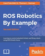
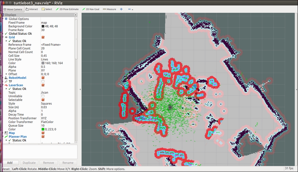
Your rviz screen should display results similar to the following screenshot:

An initial gmapping screen in rviz
- Terminal window 4: Keyboard control of TurtleBot:
$ roslaunch turtlebot_teleop keyboard_teleop.launchAt this point, you should use keyboard commands to navigate TurtleBot completely around the environment. A representation of the map is built and can be viewed in rviz as TurtleBot's 3D sensor detects objects within its range.
The following screenshot shows a map of our lab that TurtleBot produced on rviz:

TurtleBot mapping a room
Notice that light gray areas are clear, unoccupied space, dark gray areas are unexplored areas, black indicates a solid border, such as a wall, and colored spots are obstacles in the room. The area of the brightest color is TurtleBot's local map (the area the sensor is currently detecting).
When a complete map of the environment appears on rviz, the map should be saved. Without killing any of the prior processes, open another terminal window and type the following commands:
$ ssh <username>@<Turtlbot's IP Address>
$ rosrun map_server map_saver -f /home/<TurtleBot's username>/my_map
If you do not know the TurtleBot's username, after SSH'ing to TurtleBot, use the
pwdcommand to find it.The process creates two files:
my_map.yamlandmy_map.pgmand places them in your TurtleBot netbook home directory. The path and filename can be changed as you desire, but files should be saved on the TurtleBot.The
.yamlfile contains configuration information of the map and the path and name of the.pgmimage file. The.pgmfile is in portable gray map format and contains the image of the OGM.The map configuration information includes the following:
- The absolute pathname to the
.pgmimage file - The map resolution in meters per pixel
- Coordinates (x, y, and yaw) of the origin on the lower-left corner of the grid
- A flag to reverse the white pixel=free and black pixel=occupied semantics of the map color space
- The lowest threshold value at which pixels will be considered completely occupied
- The highest threshold value at which pixels will be considered completely free
In the next section, we will examine TurtleBot's mapping process from a more in-depth ROS perspective.
- The absolute pathname to the
TurtleBot builds maps using the ROS gmapping package. The gmapping package is based on OpenSlam's Gmapping (http://openslam.org/gmapping.html), which is a highly efficient Rao-Blackwellized particle filter algorithm. This approach is based on a laser scan-based SLAM implementation. Although a laser scanner would work the best for SLAM, the Kinect will provide a simulated laser scan for the TurtleBot. The ROS gmapping package contains the slam_gmapping node that takes the incoming laser scan stream and transforms it to the odometry tf reference frame.
The gmapping process is implemented by a set of parameters within the gmapping_demo.launch file in the turtlebot_navigation package. This launch file initiates the 3dsensor.launch file from the turtlebot_bringup package to handle the processing of the 3D sensor. Some of the sensor processing modules are turned off to minimize processing for this task.
The slam_gmapping node subscribes to the sensor_msgs/LaserScan messages from the camera_nodelet_manager node and the tf/tfMessage messages containing the odometry frames. The following diagram from rqt_graph shows the /tf and /tf_static topics (with tf/tfMessage messages) and the /scan topic (with sensor_msgs/LaserScan messages) being subscribed to by the slam_gmapping node. The slam_gmapping node combines this data to create an OGM of the environment. As the robot is driven around the room, the slam_gmapping node publishes the /map topic to update the OGM with an estimate of TurtleBot's location and the surrounding environment based on data from the laser scan.

slam_gmapping node
When you issue the command to save the map, the map_saver node of the map_server package gets activated. The map_saver node provides a ROS service to take the OGM data and saves it to a pair of files (the .pgm and .yaml files described in the previous section). Each cell of the OGM records its occupancy state as a color for the corresponding pixel. Free space is identified as white with a value of 0 and occupied space is identified as black with a value of 100. A special value of -1 is used for unknown (unmapped) space. The threshold values within the .yaml file make the pixel values between 0 and 100 categorized as occupied, free, or in-between.
ROS has implemented the concept of a Navigation Stack. ROS stacks are a collection of packages that provide a useful functionality, in this case navigation. Packages in the Navigation Stack handle the processing of odometry data and sensor streams into velocity commands for the robot base. As a differential drive base, TurtleBot takes advantage of the ROS Navigation Stack to perform tasks, such as autonomous navigation and obstacle avoidance. Therefore, understanding TurtleBot's navigation processes will provide the knowledge base for many other ROS mobile robots as well as a basic understanding of navigation for aerial and underwater robots.
In this section, we will use the map that we created in the Mapping a room with TurtleBot 2 section. As an alternative, you can use a bitmap image of a map of the environment, but you will need to build the .yaml file by hand. Values for map resolution, coordinates of the origin, and the threshold values will need to be selected. With the environment map loaded, we will command TurtleBot to move from its present location to a given location on the map defined as its goal.
At this point, understand that:
- TurtleBot is publishing odometry data and accepting velocity commands
- Kinect is publishing 3D sensor data (fake laser scan data)
- The
tflibrary is maintaining the transformations betweenbase_link, odom frame, and the depth sensor frame of Kinect - Our map (
my_map) will identify the environment locations that have obstacles
The following are the core terms used for autonomous navigation with TurtleBot:
- Amcl: The amcl algorithm works to figure out where the robot would need to be on the map in order for its laser scans to make sense. Each possible location is represented by a particle. Particles with laser scans that do not match well are removed, resulting in a group of particles representing the location of the robot in the map. The
amclnode uses the particle positions to compute and publish the transform from map tobase_link. - Global navigation: These processes perform path planning for a robot to reach a goal on the map.
- Local navigation: These processes perform path planning for a robot to create paths to nearby locations on a map and avoid obstacles.
- Global costmap: This costmap keeps information for global navigation. Global costmap parameters control the global navigation behavior. These parameters are stored in
global_costmap_params.yaml. Parameters common to global and local costmaps are stored incostmap_common_params.yaml. - Local costmap: This costmap keeps information for local navigation. Local costmap parameters control the local navigation behavior and are stored in
local_costmap_params.yaml.
To navigate the environment, TurtleBot needs a map, a localization module, and a path planning module. TurtleBot can safely and autonomously navigate the environment if the map completely and accurately defines the environment.
Before we begin with the steps for autonomous navigation, check the location of your .yaml and .pgm map files created in the previous section.
As in the previous section, be conscious of which commands are on TurtleBot (requiring ssh from the remote computer) and those that are on the remote computer (not requiring ssh). At this point, all terminal windows should be closed. Then, open a window as indicated and enter the commands following the $ prompt:
- Terminal Window 1: Minimal launch of TurtleBot:
$ ssh <username>@<TurtleBot's IP Address>
$ roslaunch turtlebot_bringup minimal.launch
- Terminal Window 2: Launch amcl operation:
$ ssh <username>@<TurtleBot's IP Address>
$ roslaunch turtlebot_navigation amcl_demo.launch map_file:=/ home/<TurtleBot's username>/my_map.yaml
Look for the following text on your window:
odom received!The
amcl_demolaunch file launches the3dsensor.launchfile, specifying to turn off thergb_processing,depth_registration, anddepth_processingmodules. This leaves the modules forir_processing,disparity_processing,disparity_registered_processing, andscan_processing. Themap_servernode is launched to read the map data from the file. The.xmlfiles foramcl.launchandmove_base.launchare also invoked. Theamcl.launch.xmlfile launches theamclnode and processing sets multiple parameters in the.xmlfile. Themove_base.launch.xmlfile launches themove_basenode and also starts the nodes forvelocity_smootherandsafety_controller. A more complete description of this processing is provided in the following How does TurtleBot accomplish this navigation task? section. - Terminal Window 3: View navigation on rviz:
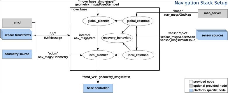
$ roslaunch turtlebot_rviz_launchers view_navigation.launchThis command launches the rviz node and rviz will come up in the TopDownOrtho view. Your rviz screen should display results similar to the following screenshot:
An initial amcl screen in rviz
When amcl_demo loads the map of the environment, TurtleBot does not know its current location on the map. It needs a little help. Locate TurtleBot's position in the rviz environment and let TurtleBot know this location by performing the following steps:
- Click on the 2D Pose Estimate button on the tool toolbar at the top of the main screen.
- Click the cursor on the location on the map where TurtleBot is located. A large green arrow will appear. Drag the mouse to extend the arrow in the direction TurtleBot is facing.
The giant green arrow helps you align the direction of TurtleBot's orientation. An example is shown in the following screenshot:

TurtleBot 2D Pose Estimate
When the mouse button is released, a collection of small arrows will appear around TurtleBot to show the direction. If the location and/or orientation are not correct, these steps can be repeated.
The previous steps seed TurtleBot's localization, so it has some idea where it is on the environment map. To improve the accuracy of the localization, it is best to drive TurtleBot around a bit so that the estimate of its current position converges when comparing data from the map with TurtleBot's current sensor streams. Use one of the teleoperation methods previously discussed. Be careful driving around the environment because there is no obstacle avoidance software running at this point. TurtleBot can be driven into obstacles even though they appear on its map.
Next, we can command TurtleBot to a new location and orientation in the room by identifying a goal:
- Click on the 2D Nav Goal button on the tool toolbar at the top of the main screen.
- Click the cursor on the location on the map where you want TurtleBot to go. A large green arrow will appear. The point you clicked will be the final location of the TurtleBot. The arrow extending from that point indicates the direction TurtleBot should be facing when it is finished.
The following screenshot shows setting the navigation goal for our TurtleBot:

TurtleBot 2D Nav Goal
The following screenshot shows our TurtleBot accomplishing the goal:

TurtleBot reaches its goal
TurtleBot can also perform obstacle avoidance during autonomous navigation. While TurtleBot is on its way to a goal, step in front of it (at least 0.5 meters (1.6 feet) in front of the Kinect) and see that TurtleBot will move around you. Objects can be moved around or doors can be opened or closed to alter the environment. TurtleBot can also respond to the teleoperation control during this autonomous navigation.
In the next section, we will examine TurtleBot's autonomous navigation process from a more in-depth ROS perspective.
At the highest level of processing, ROS navigation acquires odometry data from the robot base, 3D sensor data, and a goal robot pose. To accomplish the autonomous navigation task, safe velocity commands are sent to the robot to move it to the goal location.
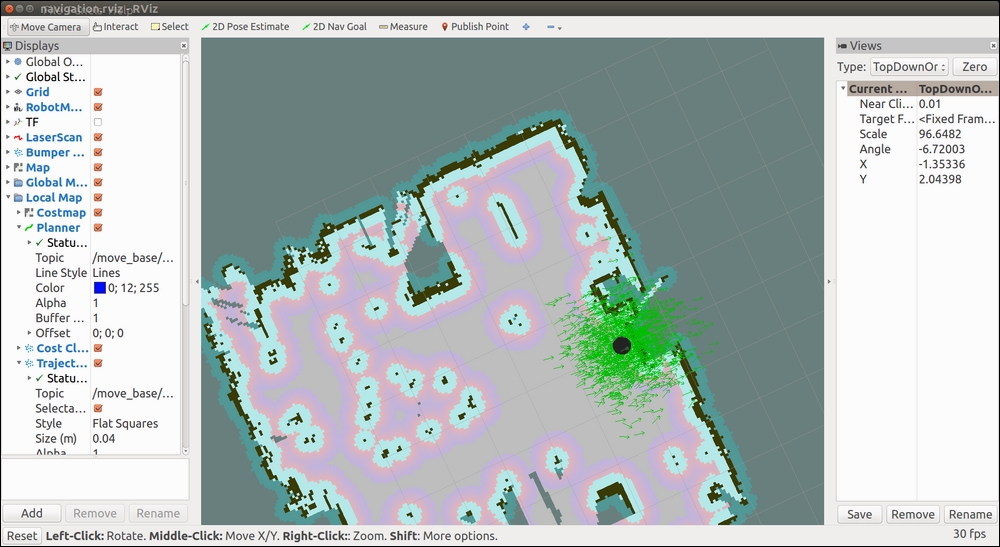
TurtleBot's navigation package, turtlebot_navigation, contains a collection of launch and YAML configuration files to launch nodes with the flexibility to modify process parameters on the fly. The following diagram shows an overview of the navigation process:
The ROS navigation process
When the amcl node is launched, it begins providing localization information about the location of the robot based on the current 3D sensor scans (sensor_msgs/LaserScan), tf transforms (tf/tfMessage), and the OGM (nav_msgs/OccupancyGrid). When a 2D Pose Estimate is input by the operator, an initialpose message (geometry_msgs/PoseWithCovaianceStamped) resets the localization parameter and reinitializes the amcl particle filter. As laser scans are read, amcl resolves the data to the odometry frame. The amcl node provides TurtleBot's estimated position in the map (geometry_msgs/PoseWithCovarianceStamped), a particle cloud (geometry_msgs/PoseArray), and the tf transforms for odom (tf/tfMessage).
The main component of the TurtleBot navigation is the move_base node. This node performs the task of commanding the TurtleBot to make an attempt to reach the goal location. This task is set as a preemptable action based on its implementation as a ROS action and TurtleBot's progress toward the goal is provided as feedback. The move_base node uses a global and a local planner to accomplish the task. Two costmaps, global_costmap and local_costmap, are also maintained for the planners by the move_base node.
The behavior of the move_base node relies on the following YAML files:
costmap_common_params.yamllocal_costmap_params.yamlglobal_costmap_params.yamldwa_local_planner_params.yamlmove_base_params.yamlglobal_planner_params.yamlnavfn_global_planner_params.yaml
The global planner and costmap are used to create long-term plans over the entire environment, such as path planning for the robot to get to its goal. The local planner and costmap are primarily used for interim goals and obstacle avoidance.
The move_base node receives the goal information as a pose with position and orientation of the robot in relation to its reference frame. A move_base_msg/MoveBaseActionGoal message is used to specify the goal. The global planner will calculate a route from the robot's starting location to the goal taking into account data from the map. The 3D sensor will publish sensor_msgs/LaserScan with information on obstacles in the world to be avoided. The local planner will send navigation commands for TurtleBot to steer around objects even if they are not on the map. Navigation velocity commands are generated by the move_base node as geometry_msgs/Twist messages. TurtleBot's base will use the cmd_vel.linear.x, cmd_vel.linear.y, and cmd_vel.angular.z velocities for the base motors.
Goal tolerance is a parameter set by the user to specify the acceptable limit for achieving the goal pose. The move_base node will attempt certain recovery behaviors if TurtleBot is stuck and cannot proceed. These recovery behaviors include clearing out the supplied map and using sensor data by rotating in place.
In the ROS commands and Gazebo section of Chapter 3, Driving Around with TurtleBot, we used the mobile_base node from the Kobuki base of TurtleBot 2 to move the real TurtleBot. The node subscribes to the topic /mobile_base/commands/velocity topic with the geometry_msgs/Twist message type. The message is a movement command with linear.x pointing forwards as velocity in meters per second. The angular.z is interpreted as angular velocity in the xy plane in radians per second. The positive angular velocity values are rotations left or counterclockwise when the robot is viewed from above.
The websites http://wiki.ros.org/kobuki_node and http://wiki.ros.org/kobuki/Tutorials/Kobuki%27s%20Control%20System describe the Kobuki base that subscribes to the topic commands/velocity with message type geometry_msgs/Twist that sets the desired velocity of the robot. The relative movement of the robot can be monitored with the topic /odom with nav_msgs/odometry type message. The odometry of the robot is based on the gyro and motor encoders.
In this section, we use the move_base package to move the real TurtleBot by specifying a target pose as position and orientation with respect to a designated frame of reference. The topic move_base_simple/goal with message type geometry_msgs/PoseStamped defines the goal pose of the robot. The website http://wiki.ros.org/move_base describes the move_base package and the move_base_simple/goal.
Similar to the instructions in the Building a map section in this chapter, you can command the TurtleBot minimal launch, launch the gmapping_demo.launch, and move the TurtleBot from its initial position forward in its x direction as an example. Be sure TurtleBot has a clear space to move.
This will require four terminals to command TurtleBot. Enter the commands as shown:
- Terminal Window 1: Minimal launch of TurtleBot:
$ ssh <username>@<TurtleBot's IP Address>
$ roslaunch turtlebot_bringup minimal.launch
- Terminal Window 2: Check initial pose after minimal launch by typing:
$ rostopic echo /odom/pose/poseYou should see the following:
position:
x: 0.0
y: 0.0
z: 0.0
orientation:
x: 0.0
y: 0.0
z: 0.0
w: 1.0
---
Use Ctrl + C to stop the display.
- Terminal Window 3: Launch the
gmapping_demoby typing the following commands:$ ssh <username>@<TurtleBot's IP Address> $ roslaunch turtlebot_navigation gmapping_demo.launch
As previously described, this launches the
move_basenode, which will be used to move TurtleBot to a specific location with a designated pose. It is not necessary to move TurtleBot around to create a map. Thegmapping_democreates an initial map that consists of values-1indicating an unknown or unmapped space.The
move_base_simple/goaltopic will be used to issue a non-action command to TurtleBot to move to the desired location. The action based implementation ofmove_baseis described in the next section. - Terminal Window 4: To move TurtleBot ahead about 1 meter, type the command:
$ rostopic pub /move_base_simple/goal geometry_msgs/PoseStamped '{ header: { frame_id: "map" }, pose: { position: { x: 1.0, y: 0, z: 0 }, orientation: { x: 0, y: 0, z: 0, w: 1 } } }' - Terminal Window 2 again: Check the final pose with the command:
$ rostopic echo /odom/pose/poseOur results showed the following:
position:
x: 0.908365634848
y: -0.0158582614505
z: 0.0
orientation:
x: 0.0
y: 0.0
z: -0.0352483477781
w: 0.99937858391
In our laboratory, our TurtleBot moved ahead with an error in the
xdistance of about 9% based on the odometry data.
In this section, we present a Python script that causes the real TurtleBot 2 to move from one position to another using locations on a map created in our laboratory. In the previous section, Driving without steering TurtleBot 2, the rviz 2D Nav Goal option was used to select the goal location of TurtleBot.
In the example, the initial pose of the TurtleBot will be set on the map using 2D Pose Estimate. Then, the Publish Points icon will be used to select goal points that act as waypoints for TurtleBot on the map. A Python script will be executed to move the real TurtleBot to several goal positions in our room as determined by the positions on the map.
In each terminal window, enter the following commands to initialize TurtleBot, select the map, and display the map with TurtleBot on the map:
- Terminal Window 1: Minimal launch of TurtleBot:
$ ssh <username>@<TurtleBot's IP Address>
$ roslaunch turtlebot_bringup minimal.launch
- Terminal Window 2: Launch amcl operation:
$ ssh <username>@<TurtleBot's IP Address>
$ roslaunch turtlebot_navigation amcl_demo.launch map_file:=/ home/<TurtleBot's username>/my_map.yaml
- Terminal Window 3: Launch rviz and display the map:
$ roslaunch turtlebot_rviz_launchers view_navigation.launch
The following screenshot shows TurtleBot on the map in rviz:
TurtleBot's initial position in rviz
To determine TurtleBot's initial pose on the map, type the following:
$ rostopic echo /initialpose
This will display the initial pose after using the 2D Pose Estimate in rviz to identify the initial position and orientation of TurtleBot in the room.
Our result for the initial pose was as follows:
header:
  seq: 1
  stamp:
    secs: 1500506112
    nsecs: 896815961
  frame_id: map
pose:
  pose:
    position:
      x: 0.172010675073
      y: 0.0527899339795
      z: 0.0
    orientation:
      x: 0.0
      y: 0.0
      z: -0.0139684328787
      w: 0.999902436682
  covariance: [0.25, 0.0, 0.0, 0.0, 0.0, 0.0, 0.0, 0.25, 0.0, 0.0, 0.0, 0.0, 0.0, 0.0, 0.0, 0.0, 0.0, 0.0, 0.0, 0.0, 0.0, 0.0, 0.0, 0.0, 0.0, 0.0, 0.0, 0.0, 0.0, 0.0, 0.0, 0.0, 0.0, 0.0, 0.0, 0.06853891945200942]
---
For the map we created, TurtleBot's position is roughly in the middle of the map representing the middle of our laboratory.
Using the Publish Point icon, select several points on the map and record the x and y coordinates of each point. The position of the cursor at any point will be displayed in a panel at the lower left of the screen. Alternatively, echo the topic /clicked_point with the following command line:
$ rostopic echo /clicked_point
Our results for two points were as follows:
header:
  seq: 6
  stamp:
    secs: 1500506877
    nsecs: 337500725
  frame_id: map
point:
  x: 3.00541186333
  y: -0.0026988487225
  z: -0.0013427734375
---
header:
  seq: 7
  stamp:
    secs: 1500506893
    nsecs: 543592195
  frame_id: map
point:
  x: 3.03029751778
  y: 3.57522583008
  z: 0.00247192382812
Our map overlays a 10 by 10 grid of squares 1 meter on a side with the origin in the center. Your map, however, may be rotated with respect to the grid, so use the Publish Point method to determine the values on your map so that they can be related to real positions in the room.
Using our map, we chose the following points from the map that indicate locations in our laboratory: (3.0, 0.0, 0.0) for the first goal point and (3.0, 3.6, 0.0) for the final position. The first point is near the wall on the right in the map and the second is near the door to the lab at the upper right corner of the map. At initialization and at the first waypoint, the orientation of TurtleBot will be chosen to be straight ahead as defined by the quaternion (0, 0, 0, 1) along the x axis. At the second waypoint, TurtleBot will be aligned with the y axis of the map with quaternion (0, 0, 0.707, 0.707) indicating approximately a 90 degree change in orientation. The following modified screenshot shows these locations:

Goal locations chosen in rviz
You should choose goal points that relate to your map and replace the items in the list GoalPoints in the following Python script. Execute our Python script by typing in a new terminal:
$ python MoveTBtoGoalPoints.py
The following Python script named MoveTBtoGoalPoints.py moves TurtleBot to the various goal positions:
#!/usr/bin/env python

import rospy
import actionlib      # Use the actionlib package for client and server

from move_base_msgs.msg import MoveBaseAction, MoveBaseGoal

# Define Goal Points and orientations for TurtleBot in a list
GoalPoints = [ [(3.0, 0.0, 0.0), (0.0, 0.0, 0.0, 1.0)] ,
               [(3.0, 3.6, 0.0), (0.0, 0.0, 0.707, 0.707)]]

# The function assign_goal initializes goal_pose variable as a MoveBaseGoal action type.
def assign_goal(pose):
    goal_pose = MoveBaseGoal()
    goal_pose.target_pose.header.frame_id = 'map'
    goal_pose.target_pose.pose.position.x = pose[0][0]
    goal_pose.target_pose.pose.position.y = pose[0][1]
    goal_pose.target_pose.pose.position.z = pose[0][2]
    goal_pose.target_pose.pose.orientation.x = pose[1][0]
    goal_pose.target_pose.pose.orientation.y = pose[1][1]
    goal_pose.target_pose.pose.orientation.z = pose[1][2]
    goal_pose.target_pose.pose.orientation.w = pose[1][3]

    return goal_pose

if __name__ == '__main__':
    rospy.init_node('MoveTBtoGoalPoints')

    # Create a SimpleActionClient of a move_base action type and wait for server.
    client = actionlib.SimpleActionClient('move_base', MoveBaseAction)
    client.wait_for_server()

    # for each goal point in the list, call the action server and move to goal
    for TBpose in GoalPoints:
        TBgoal = assign_goal(TBpose)  # For each goal point assign pose
        client.send_goal(TBgoal)
        client.wait_for_result()

    # print the results to the screen
    if(client.get_state() == GoalStatus.SUCCEEDED):
        rospy.loginfo("success")
    else:
        rospy.loginfo("failed")
When the program finishes, the terminal display should show success.
This Python script sends goal poses to TurtleBot one pose at a time to move it to a particular location. This code uses the navigation stack as described in the How does TurtleBot accomplish this navigation task? section. The rospy and actionlib packages and the MoveBaseAction and MovBaseGoal messages are used within the script and are imported at the beginning of the code. The MoveBaseAction message defines the action goal, action result, and action feedback specifically for behaviors regarding TurtleBot's movement. The MoveBaseGoal message is used to define the target pose.
The goal poses for TurtleBot are identified in the list GoalPoints. For the Python script, the goal poses in terms of position x, y, z and the orientation in terms of a quaternion were chosen as:[[(3.0, 0.0, 0.0), (0.0, 0.0, 0.0, 1.0)] and [(3.0, 3.6, 0.0), (0.0, 0.0, 0.707, 0.707)]].
Next in the code is the definition of the assign_goal function. The assign_goal function creates a message of type MoveBaseGoal and assigns the values from the pose item in GoalPoints to target pose in this message.
When the main function of this program runs, it creates the ROS node MoveTBtoGoalPoints. Then it creates an action client for the SimpleActionServer, which is configured to communicate with the move_base server and adhere to the behaviors defined in the MoveBaseAction message. The wait statement indicates that a response from the action server is necessary before proceeding to the next lines of code.
The for loop increments through each of the goal poses in the GoalPoints list and causes each of these poses to be processed by the move_base action server. The first statement in the loop calls the assign_goal function to create a MoveBaseGoal message and assign the values of that message to be the values of the goal pose. The second statement calls the action client send_goal function to send the goal to the action server. The process then waits for the server to return the results of the action and the appropriate message is displayed. When we tested our example, the success message appeared on the screen.
As a result in our laboratory, TurtleBot moved toward the wall on the right of the map and turned approximately 90 degrees left and moved toward the door at the upper right. The script completes with the reply:
[INFO] [1499983063.642908]: success
The following screenshot shows the final location of TurtleBot after the Python script is executed:

TurtleBot's final location in rviz
You can check the robot's final position as it moves on the map by typing:
$ rostopic echo /amcl_pose
Our final pose from topic /amcl_pose was as follows:
header:
  seq: 72
  stamp:
    secs: 1500584344
    nsecs: 824573719
  frame_id: map
pose:
  pose:
    position:
      x: 2.95402869322
      y: 3.30398805405
      z: 0.0
    orientation:
      x: 0.0
      y: 0.0
      z: 0.666663241366
      w: 0.745359056168
  covariance: [0.02732330983433684, -0.001682319824116263, 0.0, 0.0, 0.0, 0.0, -0.001682319824116263, 0.002880105195270488, 0.0, 0.0, 0.0, 0.0, 0.0, 0.0, 0.0, 0.0, 0.0, 0.0, 0.0, 0.0, 0.0, 0.0, 0.0, 0.0, 0.0, 0.0, 0.0, 0.0, 0.0, 0.0, 0.0, 0.0, 0.0, 0.0, 0.0, 0.004937415284215015]
The indicated position and orientation is reasonably close to the selected values. The pose only can be viewed by typing:
$ rostopic echo /odom/pose/pose
since the covariance is not relevant in this case.
TurtleBot 3 has SLAM and autonomous navigation applications similar to those described for TurtleBot 2. The sequences and commands will be briefly described in the next two sections.
Before proceeding with the next two sections, check to verify your network configuration and ROS environment variables for both the TurtleBot 3 and the remote computer are set as described in the Networking TurtleBot 3 and the remote computer section of Chapter 3, Driving Around with TurtleBot.
The same launch procedure will be used as was described previously in the Moving the real TurtleBot 3 section of Chapter 3, Driving Around with TurtleBot:
- On the remote computer, start the ROS Master with the following command:
$ roscore - In a second terminal window,
sshto the TurtleBot from the remote computer and then launch the TurtleBot basic operations with the following commands:$ ssh <username>@<IP address of TurtleBot> $ roslaunch turtlebot3_bringup turtlebot3_robot.launch
- Next launch the SLAM software in a new terminal window with the following commands:
$ export TURTLEBOT3_MODEL=burger
$ roslaunch turtlebot3_slam turtlebot3_slam.launch
- After the
turtlebot3_slam_gmappingnode has launched, information regarding the laser scans will begin to appear on the screen and run continuously updating data with each scan performed. To visualize the TurtleBot and the area that will become the map, start rviz with the followingroslaunchcommand:$ rosrun rviz rviz -d `rospack find turtlebot3_slam`/rviz/turtlebot3_slam.rvizAn rviz window should be displayed similar to the following screenshot:

An initial SLAM map for TurtleBot 3 in rviz
This is very similar to the rviz window that is generated by SLAM gmapping for the TurtleBot 2.
- Now, move the TurtleBot around the environment with keyboard control by using the following command in a new terminal window:
$ roslaunch turtlebot3_teleop turtlebot3_teleop_key.launch - When you have completely driven the robot around your environment and are happy with your map, open one additional terminal window and save the map to a file with the following command:
$ rosrun map_server map_saver -f ~/mapThe map will be saved to the home directory of your remote computer, not on TurtleBot 3. Two files will be created for the map:
map.pgmandmap.yaml. These files are the same type as those described for TurtleBot 2. - Next, this map will be used to autonomously navigate TurtleBot around the area that was just mapped. Use Ctrl + C in each terminal window to kill all the processes and then close the windows.
As in the previous section, verify the network configuration and ROS environment variables for the TurtleBot 3 and the remote computer. Also, start the ROS Master and launch the basic operation of TurtleBot 3.
To launch the navigation software for the TurtleBot 3 Burger, use the following commands in a new terminal window:
$ export TURTLEBOT3_MODEL=burger
$ roslaunch turtlebot3_navigation turtlebot3_navigation.launch map_file:=~/map.yaml
If you named the map file with a name other than map, substitute that name with the .yaml extension in the preceding command. To visualize the map and Turtlebot, start rviz with the following rosrun command:
$ rosrun rviz rviz -d `rospack find turtlebot3_navigation`/rviz/turtlebot3_nav.rviz
The rviz screen should display the map with TurtleBot 3 located within the map surrounded by a cloud of small green arrows similar to the following screenshot:
An initial navigation map for TurtleBot 3 in rviz
In the same manner as was done for TurtleBot 2, rviz should be updated with the initial location and orientation of the TurtleBot 3. To perform this update:
- Click on the 2D Pose Estimate button on the top toolbar.
- Click the cursor on the location on the map where TurtleBot is located. A large green arrow will appear. Drag the mouse to extend the arrow in the direction TurtleBot is facing.
The giant green arrow that appears will help to align the direction TurtleBot is facing. When the mouse button is released, the map will update with the new location and orientation of the TurtleBot and its surrounding area.
To autonomously navigate TurtleBot to another location on the map, indicate a goal location and orientation by performing the following steps:
- Click on the 2D Nav Goal button on the top toolbar.
- Click the cursor on the location on the map where you want TurtleBot to go. A large green arrow will appear. The point you clicked will be the final location of the TurtleBot. The arrow extending from the point indicates the direction TurtleBot should be facing when it is finished.
When the mouse button is released, TurtleBot will create a path to the goal location and begin executing the path plan. It will avoid obstacles detected by the LDS sensor. Be aware that the LDS sensor will only detect objects at the level of its own height. Objects above or below this height will not be sensed.
The many parameters involved in TurtleBot 2 navigation can be tweaked on the fly by using the rqt_reconfigure tool. This tool was previously named Dynamic Reconfigure and this name still appears on the screen. To activate this rqt plugin, use the following command:
$ rosrun rqt_reconfigure rqt_reconfigure
Nodes that have been programmed using the rqt_reconfigure API will be visible on the rqt_reconfigure GUI. On the GUI, nodes can be selected and a window with the nodes' parameters will appear with the current values and range limits. Sliders and input boxes allow the user to enter new values that will dynamically overwrite the current values. At present, TurtleBot 2 has implemented the rqt_reconfigure API as shown in the following screenshots. The following screenshot shows configuration parameters that can be changed for the /camera/depth, /camera/depth_registered, and /camera/driver:

rqt_reconfigure camera parameters
The parameters for the move_base node control can be accessed through rqt_reconfigure. These parameters are set by the move_base_params.yaml file mentioned in the previous section. This screen identifies the base_global_planner and the base_local_planner as well as how often to update the planning process (planner_frequency), and so on. These parameters allow the operator to tweak the performance of the software during an operation.
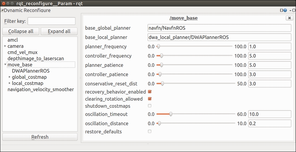
rqt_reconfigure move_base parameters
The ROS wiki provides extensive information on all aspects of setting up and configuring the navigation parameters. The following links are provided to enhance your understanding:
The following book is worth reading to gain a deeper understanding of amcl and robotic navigation:
Probabilistic Robotics by Thrum, Burgard, and Fox by MIT Press