Gazebo is a free and open source robot simulation environment developed by Willow Garage. As a multifunctional tool for ROS robot developers, Gazebo supports the following:
- Designing of robot models
- Rapid prototyping and testing of algorithms
- Regression testing using realistic scenarios
- Simulation of indoor and outdoor environments
- Simulation of sensor data for laser range finders, 2D/3D cameras, kinect-style sensors, contact sensors, force-torque, and more
- Advanced 3D objects and environments utilizing Object-Oriented Graphics Rendering Engine (OGRE)
- Several high-performance physics engines (Open Dynamics Engine (ODE), Bullet, Simbody, and Dynamic Animation and Robotics Toolkit (DART)) to model the real-world dynamics
In this section, we will load our two-wheeled robot URDF into Gazebo to visualize it in a 3D environment. Gazebo allows you to take control of some aspects of our model without an external control program. In the later chapters, we will be using simulated versions of robots in Gazebo to control joints, visualize sensor data, and test control algorithms.
To run Gazebo requires a powerful graphics card and the appropriate drivers be installed on your computer.
Note
If you have trouble with running Gazebo, refer to http://answers.gazebosim.org/questions/ or search the ROS forum at http://answers.ros.org/questions/.
Gazebo should have been installed on your computer as part of the ros-kinetic-desktop-full installation, as described in the Installing and launching ROS section in Chapter 1, Getting Started with ROS. Gazebo 7.x is the default version of Gazebo for ROS-Kinetic/Ubuntu-Xenial and is the version recommended for the exercises in this book.
To test whether Gazebo has been installed correctly, open a terminal window and type the following command:
$ gazebo
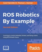
This should display an environment similar to the following screenshot:
Gazebo main screen
If Gazebo has not been installed, refer to the ROS-Kinetic installation instructions at http://wiki.ros.org/kinetic/Installation/Ubuntu or the general Gazebo installation instructions at http://gazebosim.org/tutorials?cat=install. Make sure that you install the Gazebo 7 version.
The $ gazebo command runs two different executables: the Gazebo server and the Gazebo client. The Gazebo server gzserver will execute the simulation process, including the physics update loop and sensor data generation. This process is the core of Gazebo and can be used independently of any graphical interface. The Gazebo client gzclient command runs the Gazebo GUI. This GUI provides a nice visualization of simulation and handy controls for an assortment of simulation properties.
Tutorials for Gazebo can be found at http://gazebosim.org/tutorials.
Tip
To shut down Gazebo
Use the Ctrl + C keys to kill the terminal window process after you have closed the Gazebo window.
Important commands: If at any time, your command generates a warning or error command, type $ rosnode list to determine whether there are any active nodes still lingering after you have attempted to shut down Gazebo. If any nodes are still active, use the $ rosnode kill command to list them. Next, select the number of the ROS nodes that you wish to kill. Or you can use the $ rosnode kill –a command to kill all the active nodes.
Roslaunch is a standard method used to start Gazebo with world files and robot URDF models. To perform a basic test of Gazebo, an empty Gazebo world can be brought up with the following command:
$ roslaunch gazebo_ros empty_world.launch
This test will verify that Gazebo has been installed properly. If you wish to try other demo worlds, including the gazebo_ros package, try substituting one of the following with empty_world.launch in the previous command:
willowgarage_world.launchmud_world.launchshapes_world.launchrubble_world.launch
For the exercises in this chapter, we created our own world, ddrobot.world. This world consists of a ground plane and two construction cones for you to drive the robot around. You will find this file in the ros_robotics package under ros_robotics/worlds. We will launch our dd_robot model into this world using the ddrobot_gazebo.launch launch file found in the ros_robotics/launch directory.
The Gazebo GUI is similar to rviz in many ways. The central window provides the view for Gazebo's 3D world environment. The grid is typically configured to be the ground plane of the environment on which all the models are held due to gravity in the environment. A red-green-blue axis is provided at the origin of the 3D Cartesian co-ordinate system. The red axis represents the x axis, green is y and blue is z.
Gazebo also has mouse controls to navigate the scene as shown in the following image:

Gazebo mouse control
For Gazebo keyboard shortcuts, visit http://gazebosim.org/hotkeys.
Double-clicking on a spot in the environment will cause the display to be zoomed in to that spot.
The main screen of Gazebo is divided into four main display areas: the central window, the World, Insert and Layers panels to the left, the Joints panel to the right, and the Simulation panel at the bottom. Across the top of these display areas are the Environment toolbar and the main screen menu bar. Each of the display areas of Gazebo will be described in the following sections. This overview should provide basic familiarity with the Gazebo GUI.
The toolbar at the top of the Gazebo environment display provides options for interacting with the simulation models and environment as shown in the following screenshot:
Gazebo environment toolbar
Each option represented by an icon has a label that is revealed when the cursor hovers over the icon. Keyboard shortcuts are also displayed in parentheses. The following labels appear on the toolbar icons (from left to right) and offer the following functionalities:
- Selection Mode (Esc): This selects a model in the environment when the cursor is clicked on it or a drag box is wrapped around it. The World panel displays the model's properties. When selected, a white outline 3D box is drawn around the model. A yellow disc is placed where the cursor is clicked and becomes the focal point when the mouse controls are used to move around the scene. (Hitting the Esc key will also activate this mode.)
- Translation Mode (T): This selects a model in the environment when the cursor is clicked on it or a drag box is wrapped around it. A 3D axis (red-green-blue) is drawn and centered on the model. Use the cursor and left mouse button to move the model anywhere in the x, y, and z planes. (Hitting the T key will also activate this mode.)
- Rotation Mode (R): This selects a model in the environment when the cursor is clicked on it or a drag box is wrapped around it. A 3D sphere (red-green-blue) is drawn and centered around the model. Use the cursor and left mouse button to rotate the model in the roll, pitch, or yaw directions using one of the rings. (Hitting the R key will also activate this mode.)
- Scale Mode (S): This selects a model in the environment when the cursor is clicked on it or a drag box is wrapped around it. A 3D axis (red-green-blue) with square endpoints is drawn and centered on the model. Scaling of a model is currently limited to only simple shapes. (A warning message will be displayed in the terminal window if the user attempts to scale other models.)
- Undo (Ctrl + Z): This reverses the last action.
- Redo (Shift + Ctrl + Z): This reverses the last undo.
- The next set of icons is used to create simple shapes in Gazebo: Box, Sphere, and Cylinder. Click on the icon and place the image shape anywhere in the 3D environment. The scale mode can then be used to resize the object.
- The next set of icons is used for lighting: Point Light, Spot Light, and Directional Light. Explore these if you wish to change the lighting and shadows in your environment.
- Copy (Ctrl + C): This copies the selected item to the clipboard.
- Paste (Ctrl + V): This pastes the item from the clipboard.
- In Selection mode, hold Ctrl and select 2 objects to align: Click on this icon when the objects are selected to align their axis in x, y or z and aligning to the minimum, center or maximum of the first or last object selected. (Lots of options here.)
- Snap Mode (N): In this mode, you can select the locations of two objects that you want to join.
- Change the View Angle: This changes the perspective view of the scene from various predefined angles.
- Screenshot: The camera icon will take a picture of the simulation scene and save it to your
~/gazebo/picturesdirectory. - Log Data (Ctrl + D): This will record the simulation to reproduce it later. A compressed
.logfile is produced which contains the initial full description of the whole world, then a series of world states. By default, the.logfile is saved to the~/.gazebo/logdirectory. The following screenshot shows the window that allows you to start the recording and select where the log file is stored:

Gazebo Data Logger screen
The World, Insert and Layers panels are shown in the following screenshot:

Gazebo World, Insert and Layers panel
The World panel to the left of the 3D environment provides access to all of the environment elements. These environment elements are GUI, Scene, Spherical Coordinates, Physics, Models, and Lights. By clicking on any of these labels, a properties panel will appear below the World panel with a properties list specific for that element.
The GUI element displays the camera name and pose in x, y, z, roll, pitch and yaw. The Scene selections allow the user to alter the ambient environment, the background and the shadows. The Spherical Coordinates displays the Surface Model in use and the Latitude, Longitude, Elevation and Heading. The Physics selections check whether the physics engine is enabled. If the physics engine is enabled, the user can control the real-time update rate, gravity, and constraints under the Physics tab as well as other properties. The Models list will display all models active in the environment. When the $ gazebo command is used, the only active model will be the ground_plane model. By clicking on the ground_plane label, the properties displayed will be the model name, a checkbox to make the model static, the model's pose (x, y, z, roll, pitch, and yaw) in the environment, and its link information.
These details are lengthy so you can explore them at your leisure. The last element, Lights, displays all the light sources for the environment. For our default environment, the sun is the only source. The properties of the sun are its pose, diffuse, specular, range, and attenuation. Our primary interest for this book will be the Models.
The Insert tab is behind the World panel. The Insert panel accesses two locations to allow the user to select from a number of predefined models to be added to the environment. The first location, /home/<username>/.gazebo/models, is the user's repository of Gazebo models that they have selected from the main Gazebo repository. This repository is the second selection available at http://gazebosim.org/models/.
The Layers tab behind the Insert panel will initially be empty. Visualization layers are defined in a model's SDF file to create the capability to toggle visual parts of the model on and off through the Gazebo GUI. A layer may contain one or more models. Toggling a layer on or off will display or hide the model(s) in that layer.
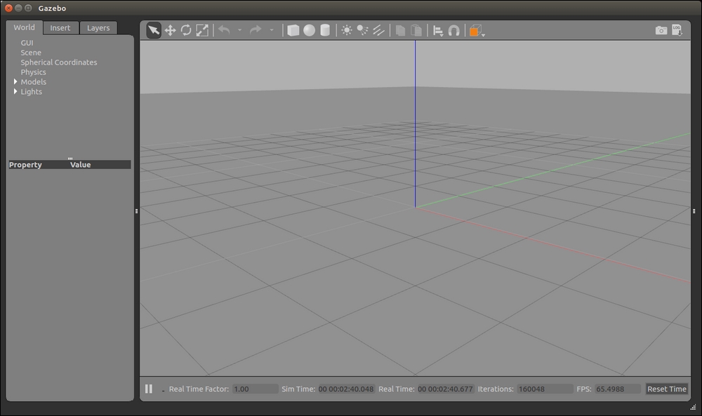
The panels to the right and left of the center display can be revealed or hidden using the three tiny rectangles in the black vertical strip. On the right side, the user can click and drag these three tiny rectangles to reveal the Joints panel. (Widen the window if the panel is not responding.) Under the Joints panel, there are three tabs labeled: Force, Position, and Velocity. There is also a Reset button to return your model to its original state (if possible):
Gazebo Joints panel
To use these controls, the model must be selected to reveal the available model joints. For the joint control, we have the following values:
- Force values are in Newton meters
- Position values are in radians or degrees (make a selection from the drop-down window), P Gain (for proportional gain), I Gain (for integral gain), and D Gain (for derivative gain) (Scroll the window using the horizontal bar at the bottom of the panel to see all of these fields.)
- Velocity values are in m/s (for meters per second), P Gain (for proportional gain), I Gain (for integral gain), and D Gain (for derivative gain)
The top-most main window menu bar provides options under the basic File, Edit, Camera, View, Window, and Help headings as shown here:
- File: Save World, Save World As, Save Configuration, Clone World, and Quit
- Edit: Reset Model Poses, Reset World, Building Editor, and Model Editor
- Camera: Orthographic, Perspective, FPS View Control, Orbit View Control, and Reset View Angle
- View: Grid, Origin, Transparent, Wireframe, Collisions, Joints, Center of Mass, Inertias, Contacts, Link Frames
- Window: Topic Visualization, Oculus Rift, Show GUI Overlays, Show Toolbars, and Full Screen
- Help: Hot Key Chart and About
These selections can be very useful. For example, if you wish to check the center of mass for your URDF in Gazebo, click on the View heading and select both the Wireframe and the Center of Mass options.
Gazebo expects the robot model file to be in SDF format. SDF is similar to the URDF, using some of the same XML descriptive tags. With the following modifications, Gazebo will automatically convert the URDF code into an SDF robot description. The following sections will describe the steps to be taken.
The <gazebo> tag must be added to the URDF to specify additional elements needed for simulation in Gazebo. This tag allows for identifying elements found in the SDF format that are not found in the URDF format. If a <gazebo> tag is used without a reference="" property, it is assumed that the <gazebo> elements refer to the whole robot model. The reference parameter usually refers to a specific robot link.
Other <gazebo> elements for both the links and joints can be applied to your robot but are not described in this book because of the extensive list and explanations of how they applied to the physics of Gazebo.
Note
Refer to the Gazebo tutorial at http://gazebosim.org/tutorials/?tut=ros_urdf for a list of these elements and their usage (Elements for Links and Elements for Joints).
The method of specifying link colors in rviz does not work in Gazebo since Gazebo has adopted OGRE's material scripts for coloring and texturing links. Therefore, a Gazebo <material> tag must be specified for each link. These tags can be placed in the model file just before the ending </robot> tag:
<gazebo reference="base_link">
  <material>Gazebo/Blue</material>
</gazebo>

<gazebo reference="right_wheel">
  <material>Gazebo/Black</material>
</gazebo>

<gazebo reference="left_wheel">
  <material>Gazebo/Black</material>
</gazebo>
Gazebo will not use the <visual> elements the same as the <collision> elements if you do not explicitly specify them for each link. Instead, Gazebo will treat your link as invisible to laser scanners and collision checking. If your model ends up partially embedded in Gazebo's ground plane, you should check your <collision> elements.
The dd_robot URDF has been updated with the <gazebo> tags and the <material> elements, as described earlier, and is stored in the downloaded file, dd_robot.gazebo. The .gazebo extension is used by the author to signify that this file is ready for use in Gazebo. An easy tool exists to check whether your URDF can be properly converted into an SDF. Simply run the following command:
$ gzsdf –p dd_robot.gazebo
or
$ gzsdf -p $(rospack find ros_robotics)/urdf/dd_robot.gazebo
This command outputs the entire SDF to the screen so you may wish to redirect the output to a file. The output will show you the SDF that has been generated from your input URDF as well as any warnings about the missing information required to generate the SDF.
Viewing the dd_robot model in Gazebo requires a launch file obtained or created by one of the following ways:
- Using the downloaded
ddrobot_gazebo.launchfile from theros_robotics/launchdirectory from the book's website - Creating the
ddrobot_gazebo.launchfile from the following XML code:<launch> <!-- We resume the logic in gazebo_ros package empty_world.launch, changing only the name of the world to be launched --> <include file="$(find gazebo_ros)/launch/empty_world.launch"> <arg name="world_name" value="$(find ros_robotics)/worlds/ddrobot.world"/> <arg name="paused" default="false"/> <arg name="use_sim_time" default="true"/> <arg name="gui" default="true"/> <arg name="headless" default="false"/> <arg name="debug" default="false"/> </include> <!-- Spawn dd_robot into Gazebo --> <node name="spawn_urdf" pkg="gazebo_ros" type="spawn_model" output="screen" args="-file $(find ros_robotics)/urdf/dd_robot.gazebo -urdf -model ddrobot" /> </launch>
This launch file inherits most of the necessary functionality from empty_world.launch from the gazebo_ros package. The only parameter that is changed is the world_name parameter by substituting the ddrobot.world world file. In addition to this, our URDF-based dd_robot model is launched into Gazebo using the ROS spawn_model service from the gazebo_ros ROS node. If you plan to reuse this code or share it, it is recommended that you add the dependency to your package.xml file for the ros_robotics package. The following statement should be added under dependencies:
<exec_depend>gazebo_ros</exec_depend>
The ddrobot.world world file contains a ground plane and two construction cones. This file can be found in the ros_robotics/worlds directory on the book's website, or you can create the ddrobot.world file from the following code:
<?xml version="1.0" ?>
<sdf version="1.4">
  <world name="default">
    <include>
      <uri>model://ground_plane</uri>
    </include>
    <include>
      <uri>model://sun</uri>
    </include>
    <include>
      <uri>model://construction_cone</uri>
      <name>construction_cone</name>
      <pose>-3.0 0 0 0 0 0</pose>
    </include>
    <include>
      <uri>model://construction_cone</uri>
      <name>construction_cone</name>
      <pose>3.0 0 0 0 0 0</pose>
    </include>
  </world>
</sdf>Now we are ready to launch our dd_robot model in Gazebo by typing the following command:
$ roslaunch ros_robotics ddrobot_gazebo.launch
This command will launch both the Gazebo server and GUI client with the dd_robot model and world automatically launched inside the Gazebo environment. Gazebo will look similar to the following screenshot:

dd_robot.gazebo in Gazebo
If your robot model behaves unexpectedly within Gazebo, it is likely because your model URDF needs further tuning to accurately represent its physics in Gazebo. Refer to the SDF user guide at http://sdformat.org/spec for more information on various properties available in Gazebo, which are also available in the URDF via the <gazebo> tag.
To understand the physics of Gazebo, it is important to play with your model in Gazebo. Use the Selection, Translation, and Rotation modes on the Environment toolbar to move your model to different positions, and then watch how the gravity model works. If you are brave, you can even manipulate the environment to experiment with the relationship of the elements. For example, remove the ground plane and see what happens.
Simple joint control of our dd_robot model is possible by using the Joints panel, which is to the right of the center environment. In selection mode, click on the ddrobot model and the model will be highlighted with a white outline box. The joint_left_wheel and joint_right_wheel joints will appear under the tabbed sections with a value of 0.000 for each of the input windows. We will experiment by changing the values of the left and right wheel joints to see the dd_robot model move around on the ground plane. Play with the values for Force, Position and Velocity to move your dd_robot. The following screenshot shows our dd_robot ready to be controlled via the Joints panel:

dd_robot.gazebo in Gazebo with the Joints panel
A greater control of our model can be achieved by adding transmission blocks to the URDF for the model joints. Gazebo plugins are also needed to simulate controllers that publish ROS messages for motor commands. A discussion of these advanced topics will be delayed until Chapter 5, Creating Your First Robot Arm (in Simulation), when the reader has a better understanding of ROS messages for control of mobile robots. Chapter 5, Creating Your First Robot Arm (in Simulation) will walk you through the construction of a URDF/SDF for a robot arm with a joint control implemented via Gazebo plugins. The implementation of transmission blocks and plugins for our dd_robot model is left as an exercise on completion of Chapter 5, Creating Your First Robot Arm (in Simulation).
Gazebo is only one simulator that can interface to ROS and ROS models. A list of other simulators, both open source and commercial, is provided along with a website reference:
- MATLAB with Simulink is a commercially available, multi-domain simulation and modeling design package for dynamic systems. It provides support for ROS through its Robotics System Toolbox (http://www.mathworks.com/hardware-support/robot-operating-system.html). MATLAB ROS examples are available at the website https://www.mathworks.com/help/robotics/examples/get-started-with-ros.html. An introduction of the MATLAB ROS interface is presented in Chapter 10, Controlling Baxter with MATLAB©.
- Stage is an open source 2D simulator for mobile robots and sensors (http://playerstage.sourceforge.net/index.php?src=stage/).
- Virtual Robot Experimentation Platform (V-REP) is a commercially available robot simulator with an integrated development environment. Developed by Coppelia Robotics, V-REP lends itself to many robotic applications (http://www.coppeliarobotics.com/).