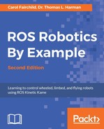
Baxter has seven rotary joints, as shown in the following figure. Each arm is often referred to as a 7-DOF arm, since motion of the arm is controlled by seven actuators (motors), which are capable of independent rotation.
Baxter's 7-DOF arms are described on the Rethink Robotics site at http://sdk.rethinkrobotics.com/wiki/Arms.
Baxter's arm joints
The arm joints are named in the following manner:
- S0: Shoulder Twist (Roll)
- S1: Shoulder Bend (Pitch)
- E0: Elbow Twist (Roll)
- E1: Elbow Bend (Pitch)
- W0: Wrist Twist (Roll)
- W1: Wrist Bend (Pitch)
- W2: Wrist Twist (Roll)
The designation of the joints as S0, S1, E0, E1, W0, W1, and W2 enables us to define, and even monitor, each of the angles for these joints with respect to the coordinates of the joints. In ROS, the angles are measured in radians. As there are 2π radians in a complete circle, one radian is 360/(2π), or about 57.3 degrees. A 90-degree angle is π/4, or about 0.7854 radians. These conversion values are given because it is often necessary to move the joints to a 90-degree position or another angle defined in radians and it is usual for us to think in terms of degrees of rotation.
The joints of the arms are connected by links of various lengths. Although all the joints are rotary joints, there is a distinction between bend joints and twist joints. The bend joints, also called pitch joints, are S1, E1, and W1. They pitch up and down on the arm and rotate about their axis perpendicular to the joint. The twist or roll joints S0, E0, W0, and W2 rotate about an axis that extends along their centerline.
Information on maximum joint speeds, joint flexure stiffness, peak torque, and other detailed arm specifications can be found at http://sdk.rethinkrobotics.com/wiki/Hardware_Specifications.
Three of the arm joints, S1, E1, and W1, are defined as bend joints and are labeled in the following figure for positive and negative direction:

Baxter's bend joints
The following table shows Baxter's bend joint limits and range of motion measured in both degrees and radians for each joint:
|
Joint |
Min limit |
Max limit |
Range |
Min limit |
Max limit |
Range |
|---|---|---|---|---|---|---|
|
in degrees |
in radians | |||||
|
S1 |
-123 |
+60 |
183 |
-2.147 |
+1.047 |
3.194 |
|
E1 |
-2.864 |
+150 |
153 |
-0.05 |
+2.618 |
2.67 |
|
W1 |
-90 |
+120 |
210 |
-1.5707 |
+2.094 |
3.6647 |
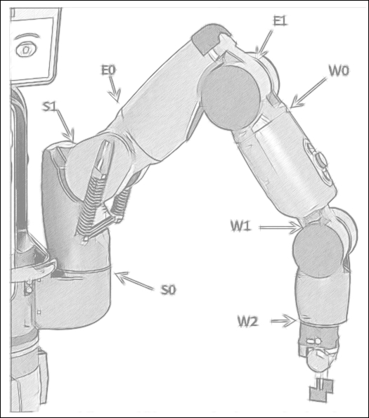
Four of Baxter's arm joints, S0, E0, W0, and W2, are defined as twist or roll joints and are labeled in the following figure for positive and negative direction:
Baxter's twist joints
The following table shows Baxter's twist joint limits and range of motion measured in both degrees and radians for each joint:
|
Joint |
Min limit |
Max limit |
Range |
Min limit |
Max limit |
Range |
|
in degrees |
in radians | |||||
|
S0 |
-97.494 |
+97.494 |
194.998 |
-1.7016 |
+1.7016 |
3.4033 |
|
E0 |
-174.987 |
+174.987 |
349.979 |
-3.0541 |
+3.0541 |
6.1083 |
|
W0 |
-175.25 |
+175.25 |
350.5 |
-3.059 |
+3.059 |
6.117 |
|
W2 |
-175.25 |
+175.25 |
350.5 |
-3.059 |
+3.059 |
6.117 |
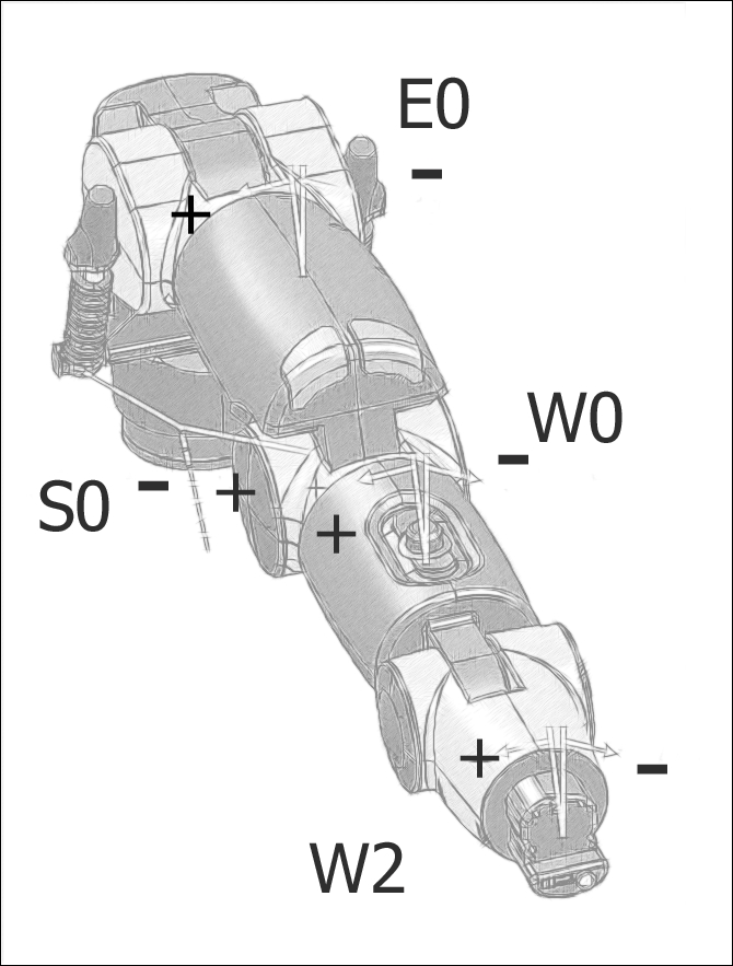
Before we discuss the details of the arm positions and orientations, it is necessary to define a base coordinate system from which other positions are measured. The following figure shows Baxter's reference coordinate system:
Baxter's base coordinate system
Standing behind Baxter, the positive x axis runs forward, along the centerline of Baxter, the positive y axis runs to the left from the centerline, and the positive z axis runs up vertically. The z axis center of Baxter's base coordinate system is at the base of Baxter's torso. This is the z=0 position. The x=0, y=0 position is behind Baxter's front plate, along the centerline on the vertical axis.
An important use of this base coordinate system is to define the position of the grippers at the end of Baxter's arms in terms of the distance in x, y, and z from the base origin considered (0, 0, 0). This is useful because, when positioned on a pedestal, Baxter has a base coordinate system that does not move during operations. However, the coordinates of each joint and the grippers will change as Baxter performs various tasks.
Cartesian positions are defined in meters in ROS, as defined in REP 103, titled Standard Units of Measure and Coordinate Conventions (http://www.ros.org/reps/rep-0103.html).
Another measure for a three-dimensional object is its orientation or angles with respect to a given coordinate system, usually a coordinate system centered on the object itself if it is stationary. We will discuss the orientation of Baxter's grippers when the transformation of coordinate systems, tf, is introduced.
In the previous figure, Baxter's outstretched arms represent the joint angles of zero degrees for all its joints. The various conventions for measuring the distance and rotation of Baxter's grippers will be presented later.
There are four modes of controlling Baxter's arms: joint position, joint velocity, joint torque, and raw joint position control. Note the descriptions and the important differences between these four joint control modes:
- Joint position control: This mode is the most fundamental control mode and is the primary method for controlling Baxter's arms. The angle of each of Baxter's joints is specified in a message to the motor controllers, which contains seven values—one value for each of the seven joints. The motor controller processes the message, checking for collisions in the URDF model between the two arms and also between the arms and the torso. If a potential collision is detected, the collision-avoidance model plans offsets to the commanded path to avoid impact.
- Joint velocity control: This mode is for advanced control of Baxter's arms. Joint velocities are specified for the joints to simultaneously achieve. The joint command message will contain seven velocity values for the controllers to achieve. Collision avoidance and detection is applied. If the velocity given in a command would take a joint to a position beyond its limits, no joints will move. This mode is dangerous and extreme caution should be used.
- Joint torque control: This mode is also for the advanced control of Baxter's arms. Joint torques are specified in the command message, which will contain seven torque values for the controllers to simultaneously perform. Collision avoidance and detection is not applied. This mode is dangerous and extreme caution should be used.
- Raw joint position control: This mode provides a more direct position control, leaving the execution of joint commands primarily for the controllers. Collision avoidance and detection is not implemented and motor velocity limits are not monitored. This mode is dangerous and extreme caution should be used.
For an in-depth description of the joint control modes, refer to Rethink's wiki at http://sdk.rethinkrobotics.com/wiki/Arm_Control_Modes.
Rethink provides two options for grippers Baxter can have: electric grippers and suction grippers. The electric gripper, as shown on the left in the following image, has two fingers with removable inserts to allow different configurations of the gripping surface. Force control of the grippers allows them to pick up rigid and semirigid objects. The electric grippers can grasp an object from the inside or outside. The gripper can open to 144 mm (approximately 5.6 inches) to grasp an object, though the fingers have various configurations within this grasping range.
The suction gripper supports the attachment of a single vacuum cup or a multicup vacuum manifold. The image shows a single suction gripper (on the right). The gripper is powered by an external air supply line. This gripper works well on smooth, nonporous, or flat objects:
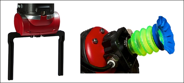
Baxter's electric and suction grippers
Each of Baxter's arms has a number of sensors on the cuff at the end of the arm. An integrated camera is mounted on the cuff and is pointed toward objects that the gripper could potentially pick up. The camera has a frame rate of 30 frames per second and a maximum resolution of 1280 x 800 pixels. An infrared sensor pointing in the same direction can detect distances from 4 to 40 cm (1.5–15 inches). The following image shows the positions of the cuff camera and the infrared sensor. Each cuff also contains a three-axis accelerometer:
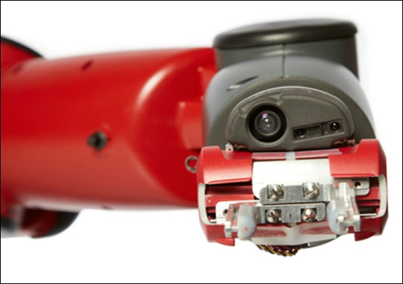
Baxter's cuff camera and infrared sensor
Additional information on these sensors can be found at the following websites: