
6
Exploring Reactions Through Outputs
Getting a response through and with our wearable is exciting. The world of outputs and actuators can help us do that. If a wearer must create the input themselves, it can become a burden. Implicit interaction (Schmidt, A., 2000) is possible by using sensors to capture the data. Then, we can process this with Arduino for the wearer; that can be stored or is interpreted for an output.
Important note
Implicit interaction is about putting humans first and having technology as a background system. It is an approach that engages a wearer and creates systems that don’t require extra steps or actions to allow them to work as intended. Making systems fun and engaging for a wearer is a great way to enhance a system’s use.
This chapter describes the outputs that bring your projects to life. We will experiment with light, from LEDs to NeoPixels, and more. We will also learn about sound, movement, and heat. Learning these skills will enhance the capabilities and interactions we can make with our wearables. Let’s make things happen!
In this chapter, you will learn about the outputs that can add huge value to a wearable. After defining the types of outputs and why they are useful, we will put what we’ve learned into practice and create circuits that react to the inputs they receive.
By the end of this chapter, you will know about a range of outputs that you can add to your wearable designs and be able to code your circuit board to react and display visual effects, auditory properties, and haptic feedback, based on the sense of touch.
In this chapter, we’re going to cover the following main topics:
- About action – outputs and responses
- Visual – light, color, and vision
- Auditory – sound, tone, and audio
- Haptic – actuators, motion, motors, and vibration
Technical requirements
This chapter is all about learning how to use different outputs to show reactions, or actions when we receive sensor data. Many outputs are featured in the chapter, so there isn’t a required list. However, you may want to give a few of the electronic circuits a try so that you can choose or swap items out from the following list:
- Arduino as the IDE
- Flora V3/Circuit Playground Classic/Gemma M0 boards
- Various sensors and outputs – NeoPixels, OLED, piezo, and a vibration motor
- Components for hooking up the motor – 10 KΩ resistor, PN2222 transistor, 270 Ω resistor, diode, and a small 3-5V miniature cooling axial fan or motor
About action – outputs and responses
Output responses provide a wearer with essential feedback. It can also enhance the wearer’s experience. Besides that, delight and fun are an important part of people’s experience of technology. Offering long-term value makes the difference between a wearable being worn or being left in a cupboard somewhere!
In this section, we will learn about outputs. Then, we will try some sample circuits to solidify our knowledge. These circuits will be more complicated than previous examples we’ve tried because we will create a circuit with an input that sends data to the board, which will perform an action, cause a reaction, or provide an output of some description based on that data.
Let’s start by learning about some of the outputs we can use, starting with visual output.
Visual – light, color, and vision
Materials that glow and light up always add an element of excitement or wonderment to a wearable. The good news is that we can add light to our wearables in many ways!
There are a few ways we can enhance our projects with both light and vision. In this section, we will look at the following:
- LEDs
- NeoPixels
- EL wire
- Display screens
Throughout this book, we have played with LEDs, so we already know about these in a basic way. Let’s start with an overview of LEDs, then explore other ways we can add light to our wearables!
LEDs
An LED is a diode, as we’ve seen previously. Since it’s a diode, electricity travels through it in one direction. The color of the light is determined by the energy gap distance inside the LED. They come in a huge variety of sizes, shapes, and colors. LEDs can also be ultraviolet and infrared, so we can’t see the light, but we can use them to control other devices by sending a signal. An LED has low power needs – you’ve already tried using LEDs with coin cell batteries – but they also have a long lifespan. Many new cars use LEDs in their lights because of their efficiency.
When buying LEDs, you may also want to check their lumen value, which is a light intensity rating. More intensity can require more power, so also check the power requirements. Generally, for our wearable projects, try to find LEDs that are around 3V so that they work with your circuits easily. Remember, we can look at a components data sheet to find out more about it.
Filament-style LEDs offer a variety of effects. One end of the filament has a very small hole in the metal connector. This end is for power. The end with no hole in it is the ground connection.
LEDs can have their brightness controlled through a higher resistor value; try a 330 or a 550 Ohm resistor in your circuit if the LED is too bright. Our eyes always perceive a green LED as brighter than others, so I typically use a higher resistor when I use green. We can also alter how the LED is viewed by diffusing it. This can be done by using layers of fabric, adding sequins or a covering, or using plastic pieces such as Perspex or acrylics of different colors and thicknesses. These can be molded and shaped too:
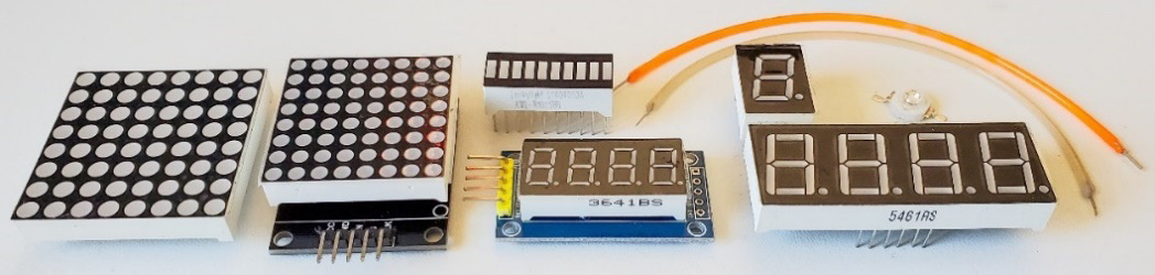
Figure 6.1 – LEDs – matrix and segment styles
There are also LEDs in a matrix shape, 7-segment displays, and bar graphs with tombstone-style LEDs, as shown in Figure 6.1, the filament style is also shown here.
Lastly, there are interesting wireless LEDs, as shown in Figure 6.2. They have a conductive main coil around them, which is their power source. The LEDs have coils at their base that conduct power from this main powered coil. The closer the LEDs are to the power coil, the brighter they will be. You can get the LEDs in a variety of colors and sizes:
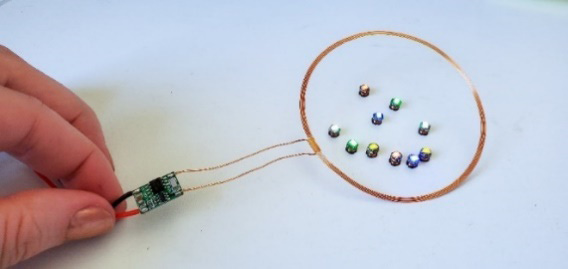
Figure 6.2 – Wireless LEDs – magic!
These coil-style wireless LEDs can be a lot of fun and if you embed the power coil into a thin garment area, it adds a little magic to a wearable!
NeoPixels
A NeoPixel, as shown in Figure 6.3, is an individually addressable RGB color pixel strip that is made with an LED driver with a single wire protocol. The NeoPixel was the first widely accessible, programmable, maker form of digital RGB LEDs. There is one data wire to transmit the data between devices. It is an Adafruit brand and its lights need a microcontroller to be used. They are very quick to hook up because of the single wire protocol – we just need to define a data pin! There are also many libraries and code examples to help you get started and, of course, the mega guide on the Adafruit website (https://learn.adafruit.com/adafruit-neopixel-uberguide):
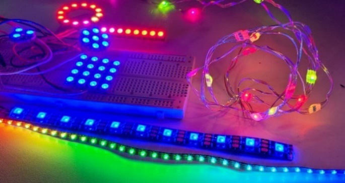
Figure 6.3 – Styles of NeoPixels
They can be used individually or in much larger chains with many lights. As you may recall, when we connect a single LED, we also hook up the power, a resistor, and ground. A NeoPixel is a full-color LED (red, green, and blue), with a driver chip embedded. There is also an RGBW version that has a white LED. You can connect many through one data pin, so it is really exciting to get them working. I love NeoPixels so much and they always add so much interest and visual interactivity to a project.
From my experience and observations, once someone learns about NeoPixels, they usually stick with them! They come in many shapes and forms, including grids, lines, and circles. You can buy them in different quantities along a long strip, a strand, or in matrices and shapes. See what types you can find because they are always fun to experiment with. The strips also come in a variety of weather-proofing thicknesses. Some can completely keep water out while others are good at repelling it. You can also usually get black or white strips so that they match your project better.
If you want individual NeoPixels, you can buy ones that are sewable with sew tabs. Typically, strips come in quantities of 30/60/144. These can be cut to the amount you need for your project. You’ll need to solder the connective ends onto it if you cut it. We’ll look at this in more detail in Chapter 10, Soldering and Sewing to Complete Your Project. The strand versions are more flexible and work best for sewing organic shapes or if you want to wrap them around something. There is also a version of the strip with croc clips on the end so that you can get started right away!
When buying NeoPixels, be sure to note the type that you are buying as it will have implications for when you code it later. Typically, you need to know if you have an RGB or RGBW version. The W version also has true white. You’ll recognize that it’s RGBW if you look at the NeoPixel and it’s divided in half with a yellow semi-circle. There is also a version of the strip NeoPixels that is an angled sidelight. They face downwards and not facing the top of the strip. They can be good for putting a strip between a seam or on the bottom of something.
Electroluminescent (EL) wire is great for adding interesting effects to a wearable (Figure 6.4 shows a variety).
You might have come across something that looks like a Tron-style item, with a hue of color outlining an item of clothing, for example. It’s often used to add light to cosplay or costumes. The copper wire core is coated with phosphor and when we add electricity, it glows. It’s covered in clear plastic or colored plastic for different effects. It’s quite bendable and you can find a style with a sewable edge. That’s usually the style I buy. It makes it a lot easier to add to your wearable projects.
EL wire comes in different colors, styles, and lengths. You must buy it with a driver/inverter (this converts DC voltage into a higher AC voltage) battery pack to power it. The inverters give off a little noise, so be aware of that. It’s like a slightly high-pitched hum; some are louder than others. You can always wrap the inverter in padding or bubble wrap to quieten it:
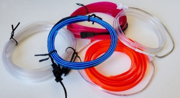
Figure 6.4 – EL wire samples
Note that EL wire seems to have a life span of a few years, so you may want to consider how you include it in your projects as it may need to be replaced. Lastly, you can cut EL wire if it is too long for your project, and it will glow up to the end of where it was cut.
Lastly, there is also EL panel and tape. These are thin sheets that glow and tend to be brighter than the wire. It’s a larger area too, so think through where it would best suit your wearable. You can see these panels and more at https://elpanelandtape.co.uk/el-panel/.
I hope you enjoyed the fun factor that an EL wire can add to your wearable. Now, let’s look at display screens.
Display screens
We can add a display screen to our wearable as an output that relays information or messages to the wearer. There are a few different types, and they offer different features. In this section, we’ll look at OLED, LCD TFT, and eInk/ePaper screens because they can be integrated into our wearable with minimal wires, and they offer a crisp display. Then, we’ll finish by looking at 16x2 LCD screens.
OLED
An Organic Light-Emitting Diode (OLED) is a display that comes in several sizes (Figure 6.5). There are small OLEDs with crisp text output because of their high contrast.
One of the more popular ones is the 0.96-inch display, which has 128×64 pixels. There is also a 0.91-inch display that measures 128x32 pixels, and a 1.12-inch display comprising 128x128 pixels. Each pixel is turned on or off by the controller, so they are very bright, and it reduces the power consumption. They have different display colors to choose from, including white, blue, and yellow.
Most of these displays have two pins for I2C for communication, and a ground and power pin. Some versions have a RESET pin. Other OLED displays communicate using the SPI protocol:
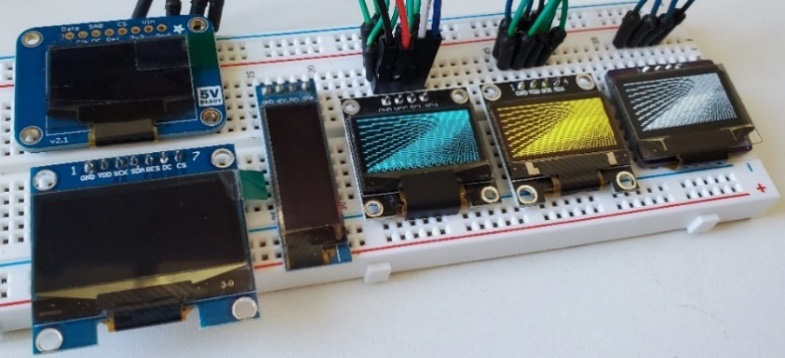
Figure 6.5 – A selection of OLED displays – SPI (left) and I2C (right)
The OLED display is a self-light-emitting technology. It’s made from a thin, multi-layered organic film that is placed between an anode (negative) and a cathode (positive).
Important Note
The order of the pins on the OLED screen can be different for different brands. Always check the pins before you hook it up and turn it on. I’ve lost an OLED this way by “cooking” the component with a short circuit! This means it was shorted because the pins were hooked up incorrectly.
Lastly, there are transparent OLED displays. A new-to-the-market OLED from DFRobot has blue illumination color, is 1.51 inches, and has a resolution of 128x64, as shown in Figure 6.6:
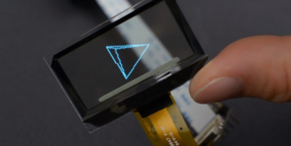
Figure 6.6 – A transparent OLED
You can read more about this OLED at https://www.dfrobot.com/product-2521.html.
LCD TFT (thin-film transistor)
These are colorful and bright displays that can add great feedback to a wearable (Figure 6.7). An LCD TFT is a thin-film-transistor, liquid-crystal display. This is a variant of a liquid-crystal display, which improves the image through thin-film-transistor technology. The screens come in many different sizes and most follow the SPI protocol (see Chapter 5, Working with Sensors: All about Inputs!).
Larger than the OLEDs we learned about, there is a 2.4-inch LCD TFT module with a display with 240x320 resolution and 65K RGB colors. Usually, the displays have small mounting holes to make them simple to incorporate into your design. Adafruit has a 1.44-inch display with a 128x128 color pixel TFT LCD that includes a Micro SD card reader on it. It uses a TFT driver so that it can refresh the images at a fast rate, though this will also depend on the circuit board you use with it.
Because of the card reader, you can load full-color bitmaps from a FAT16/FAT32-formatted Micro SD card. Lastly, there are also circular TFT screens that you can add to a project. They are the size of a standard watch face:
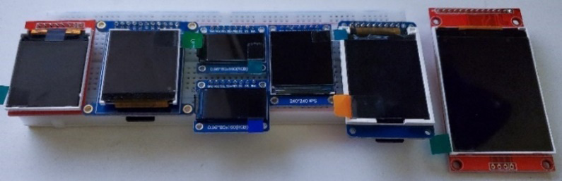
Figure 6.7 – Various LCD TFT displays
Creating a touch screen for your project is possible with an in-plane switching (IPS) Super TFT. Some have a capacitive touch option and IPS is considered an advanced screen because the technology that it uses improves viewing through a wider angle. All these displays can be used with extensive libraries, which we will look at in more detail later in this chapter. The libraries will help us get the most out of these amazing displays!
The main difference is that an OLED is generally a single color and super bright definition, while the LCD TFT is great for displaying color images.
eInk/ePaper
These displays vary in size and color (Figure 6.8). There are monochrome versions, such as the 2.9-inch Grayscale eInk display that’s 296x128 pixels from Adafruit. There is also a 2.9-inch version with red, black, and white as the display colors. Also, they come in sizes of 1.54 inches, 200x200 or 152x152 pixel displays, and 2.7 inches. eInk is a type of static display. When used, the image is written to the screen, and it will stay there when the power is off.
Their surfaces make them easy to read because they don’t have a shine to them. These displays need a lot of pins to connect, so be aware that you’ll have to choose a circuit board with three SPI pins and possibly up to four control pins for an SD and SRAM.
An eInk without color will refresh a lot quicker than the tri-color (red, black, and white) versions:
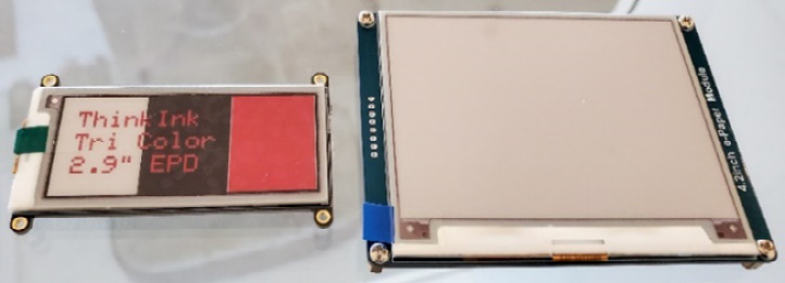
Figure 6.8 – eInk/ePaper displays
If you are using a Circuit Playground Express board (the Classic does not have enough RAM) and if you want to easily add one of these screens, there is a bolt-on gizmo that has a screen with M3 standoffs that complete the connections between the screen and circuit board.
16x2 LCDs
Lastly, these are very common and at one point, they would have been used in many projects. Typically, they are included in basic Arduino kits and are very low cost. Many have a 16-pin design, so you need to use a circuit board that can handle that many pins, though increasingly many come with an adaptor board so that you can use the I2C protocol. This does add to the bulky size of the screens though! Figure 6.9 shows an example of this screen. They come in different single colors, such as white, blue, and red, and some have different backlight options, so you can have white text on a blue background, for example:
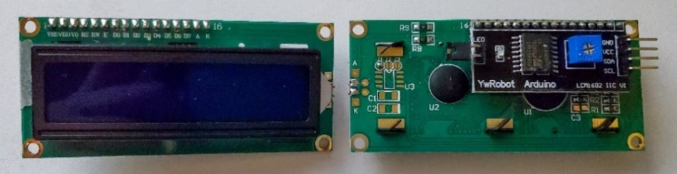
Figure 6.9 – LCD with an I2C adapter board – front (left) and back (right)
Because of the crisp, bright, and low cost of the OLEDs and TFTs, they seem to be used less in wearable designs. They can be chunky and heavy, so, as we have discussed previously, this should be a consideration when creating a wearable.
Take some time reflecting on the light sources we’ve identified in this section. Write notes in a journal about how you could incorporate light and vision into a wearable. Often, making notes, doodles, or drawings as reflections spawn ideas to build on later. Think about how the visual element would work – does the wearer actively engage with it, or is it triggered by a sensor? Is the visual component communicating to the wearer or others around them? How noticeable will it be, is it for fashion purposes, or does it enhance someone’s daily life?
Light and vision are a very important part of feedback on a wearable technology design. There are so many options when choosing how to communicate the information the wearer needs to be aware of. Consider when the light should be on and what its role is – communication with the wearer or those around the wearer. Let’s jump into some activities for using light and vision.
Activity 6.1 – learning about NeoPixels – a Hand HEX system
This is going to be the biggest project so far in this book. In this activity, we are going to get complex and build a system that will be useful to visual designers in many different fields. As we’ve seen, HEX codes and RBG values are important when we are programming NeoPixels. Using a HEX code is how we choose the colors to display. We use three values – red, green, and blue – which make up the output color.
In this circuit, we want to use a color sensor to detect any color around us, even if it’s a color on a drink can nearby! Then, we want to use that color to light our NeoPixels. We aren’t going to stop there, though! We will also hook up an OLED screen so that we can see the HEX values as their numerical values on a screen for additional output. This is so we can use that exact color in any other sketches we are writing, or for any designers so that they can use it in their work. Pretty cool, hey?
This activity will take us through mapping, hooking up, and programming our circuit board to get it to function. If you want to sew it together, you can do that here or you can wait until a little further into this book. In Chapter 10, Soldering and Sewing to Complete Your Project, we will learn more about techniques to complete wearables.
A Note for Future Circuits You Design
It’s always good practice to connect the power pin last. Sometimes, especially if we didn’t disconnect our board from the computer, we can get a surge on the power connection. This can damage our components!
You can use a glove that you already have if you think it is suitable or get creative and make your own. It’s great practice and then you’ll have an additional skill for creating your wearables. Remember: it only needs to be a prototype.
The parts list for a Hand HEX system is shown in Figure 6.10. They are as follows:
- Sewable or another color sensor
- NeoPixels, in your chosen form – strip, strand, or shapes
- A glove (buy one, make your own, or upcycle an existing glove)
- An OLED screen. Choose your preferred color and size – I’m using 128x128 yellow/blue
- An Adafruit Flora board
- A rechargeable LiPoly battery
Now that we have the materials, my first step is to map out the circuit in my notebook. I will assemble all my parts and then work through the pinouts:
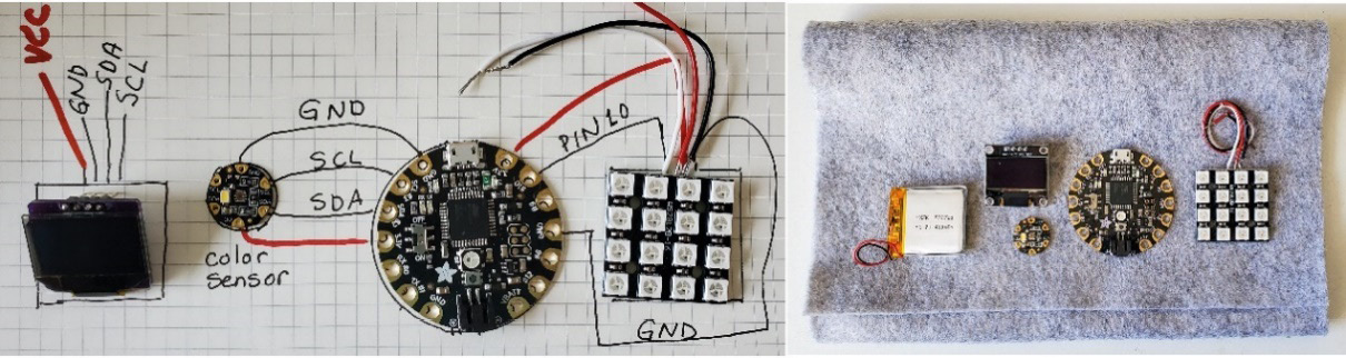
Figure 6.10 – Mapping the complete circuit and the parts for the Hand HEX system
Figure 6.10 also shows my map of the circuit connections that I’ll follow. We’ll build this project in stages. This is a great way to work because then, as we proceed through the circuit in complexity, we can fix errors as they happen. We’ll know that our circuit works as we build it. There will be three parts: the color sensor, then the OLED, and then the NeoPixels.
First, let’s add the color sensor.
Part 1 – color sensor
I’ll start by hooking up the Flora sewable color sensor to the Flora board. It uses the I2C protocol that we learned about in the previous chapter. To connect the sensor and Flora, you must set the following:
- Sensor 3V to Flora 3.3V
- Sensor GND to Flora GND
- Sensor SCL to I2C Clock on Flora (SCL pin 3)
- Sensor SDA to I2C Data on Flora (SDA pin 2)
Once you’ve connected them (Figure 6.11), plug the board into your computer so that we can try out the sensor:
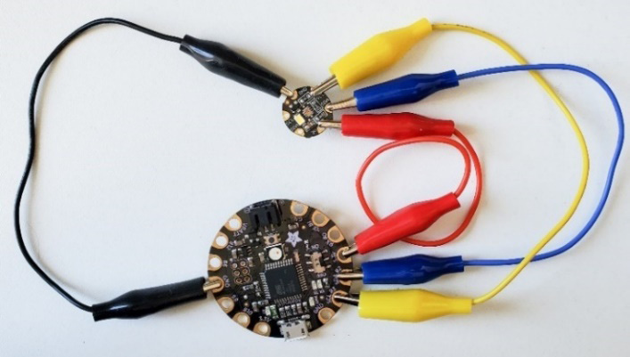
Figure 6.11 – Color sensor connected to Flora
Let’s open the Arduino IDE and install a library to use this sensor. Open the Library Manager area (Figure 6.12) and search for Adafruit TCS34725:
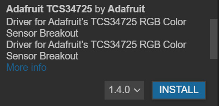
Figure 6.12 – Installing the library for the color sensor
The color sensing library didn’t come up when I searched the exact name, so if you don’t see it in the list, try searching for color sensor – that worked for me. When you do click Install, it will ask about dependencies. As shown in the following screenshot you’ll want to choose Install all:
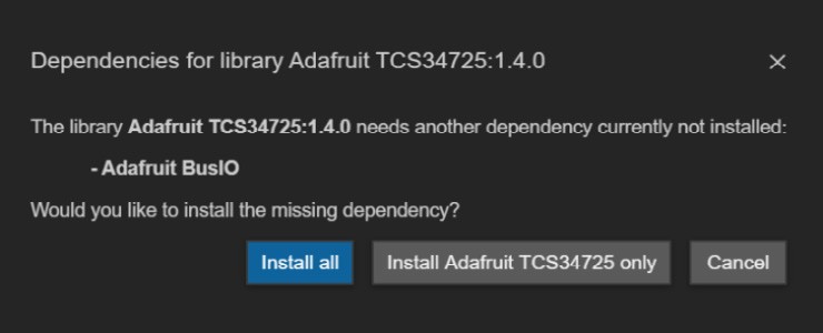
Figure 6.13 – Installing the dependencies
Be sure to wait for the notification stating that you have successfully installed the library. Sometimes, there is a glitch with the Arduino IDE 2.0 where you need to repeat this process and try the install process more than once as it may not install the library the first time. If you have the installed messages in the output window, then you’re good to go!
Because this library is used for a slightly different color sensor, we’ll use my modified code at https://github.com/cmoz/Ultimate/tree/main/C6/C6_ColorSensor for this example:
#include <Wire.h>
#include "Adafruit_TCS34725.h"
Adafruit_TCS34725 tcs = Adafruit_TCS34725(TCS34725_INTEGRATIONTIME_50MS, TCS34725_GAIN_4X);
void setup() {
  Serial.begin(9600);
  Serial.println("Color View Test!");
  if (tcs.begin()) {
  Serial.println("Found sensor");
  } else {
  Serial.println("No TCS34725 found");
  while (1);
  }
}
void loop() {
  uint16_t clear, red, green, blue;
  tcs.setInterrupt(false);
  delay(60);
  tcs.getRawData(&red, &green, &blue, &clear);
  tcs.setInterrupt(true);
  uint32_t sum = clear;
  float r, g, b;
  r = red;
  r /= sum;
  g = green;
  g /= sum;
  b = blue;
  b /= sum;
  r *= 256; g *= 256; b *= 256;
  Serial.print("HEX: 	");
  Serial.print((int)r, HEX); Serial.print((int)g, HEX);
  Serial.print((int)b, HEX); Serial.print("	 	 RGB: 	");
  Serial.print((int)r ); Serial.print(" ");
  Serial.print((int)g); Serial.print(" ");
  Serial.println((int)b); Serial.println();
}
Upload the sketch to the Flora board and open Serial Monitor. You should see a display of the color values in the output, as shown in the following screenshot:
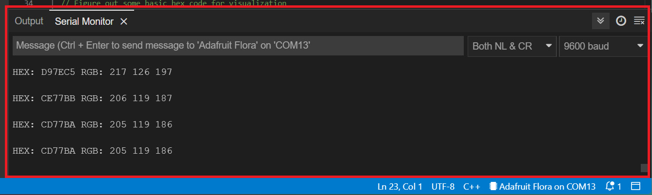
Figure 6.14 – Serial Monitor output from the color sensor
Your color sensor blinks as it’s sensing. The output to the monitor depends on the color of the item you hold over the sensor. I held a pink item, which is why I was given that readout.
Now that we have one part of our circuit working, we can connect the NeoPixels, which we’ll use to display the color of the item we are sensing. Remember, though, that this will only be as accurate as the LEDs can create, so it won’t be an exact match.
Part 2 – OLED
Unplug your Flora board from your computer and hook up the OLED display. Connecting the OLED should be familiar to you now because it follows the same I2C protocol that we covered in Chapter 5, Working with Sensors: All about Inputs!. The OLED also has four pins, two of which are for the I2C protocol. As mentioned previously, connect SDA on the screen to SDA on the Flora, and connect the SPI on the screen to the SPI on the Flora. Then hook up the ground pin and finish with the power pin.
We are using the same SDA and SCL pins because each of the components we are putting on these pins has a unique address. If you are curious about the address for your components, then you can run the sketch that outputs the address of your I2C devices.
To easily program the OLED, let’s install a library. Open the Library Manager area and search for Adafruit_SSD1306. This library will also ask you to install Adafruit_GFX at the same time, so install both (see Chapter 4, Implementing Arduino Code Using Gemma M0 and Circuit Playground, if you need more guidance on installing libraries):
#include <Wire.h>
#include "Adafruit_GFX.h"
#include "Adafruit_SSD1306.h"
#define SCREEN_WIDTH 128
#define SCREEN_HEIGHT 64
Adafruit_SSD1306 oled(SCREEN_WIDTH, SCREEN_HEIGHT, &Wire, -1);
void setup() {
  Serial.begin(9600);
  if (!oled.begin(SSD1306_SWITCHCAPVCC, 0x3C)) {
  Serial.println(F("SSD1306 allocation failed"));
  while (true);
}
  delay(2000);
  oled.clearDisplay();
  oled.setTextSize(3);
  oled.setTextColor(WHITE);
  oled.setCursor(0, 10);
  oled.println("Hello World!");
  oled.display();
}
This time, there isn’t anything in our loop() because this code is just checking everything is working. The OLED should now be displaying text that says Hello World. Play around with this code to have it display something else, such as Ultimate Wearables! This is a good way to get to know the code. When you’ve finished trying different effects and code, we can put the color sensor and OLED code together.
Open your code for the color sensor and save it as a new file. Then, add the libraries we are using, add the initialization, and then the rest of the code.
Your turn: try to combine the code. It’s good practice to combine the code yourself first. You can build it up with each new function you want your wearable to perform. Try it now with the two components:
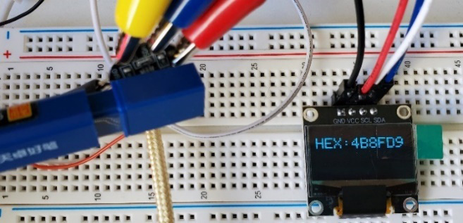
Figure 6.15 – The OLED display showing the HEX reading taken from the color scanner
The code from https://github.com/cmoz/Ultimate/tree/main/C6/C6_ColorSensor_andOLED will contain both elements – that is, the color sensor and the OLED. Upload it to your Flora board and then run it. Test it by holding something of color against your color sensor. Figure 6.15 shows the OLED displaying a HEX value for a blue pencil I scanned by holding the end against the sensor. We now have an input that is receiving data and creating an output based on that data!
Part 3 – NeoPixels
Let’s create a second output that will visually echo the color that we are scanning with the color sensor.
Make sure you unplug the Flora board from the computer before you hook up the NeoPixels. Once unplugged, connect the NeoPixels to the Flora board. Your configuration of NeoPixels might be different than mine. I’m going to use the strand version. Whatever version you choose, there will be one data pin and a power and ground pin:
- Connect your NeoPixel Data In pin to a pin that is available of your choice. This pin will be added to the code. I’m choosing pin 10 on the Flora board.
- Then, connect the power and ground of the NeoPixel to the power and ground of the Flora.
- In the Arduino IDE, add the Adafruit NeoPixel library. This will install sample files for us that we will use to test whether our lights are working. Open the strandtest file by going to File | Examples | Adafruit NeoPixel | strandtest.
Change the #define LED_PIN 6 line of code so that it contains the same value as your pin; I chose pin 10. The new line of code will look like this: #define LED_PIN 10. The line after that one is a count of the number of NeoPixel LEDs being used. Count the lights you are using in your strip, strand, or shape, and put this number in. Mine looks like this: #define LED_COUNT 8. Note that if you are using RGBW pixels, then you need to change NEO_GRB in the following code line:
Adafruit_NeoPixel strip(LED_COUNT, LED_PIN, NEO_GRB + NEO_KHZ800);
You must change it to NEO_RGBW:
Adafruit_NeoPixel strip(LED_COUNT, LED_PIN, NEO_RGBW + NEO_KHZ800);
The NeoPixels will still work if this isn’t correct, but you will see some unlit NeoPixels when they are supposed to be white, for example. Some strange lighting effects will happen, so you will know that you should change the code. Upload the sample strandtest code to the Flora board.
Once uploaded, you should see a wonderful display of colors and effects.
Do they light up? If not, make sure you’re using the Data In (DI) line and not the Data Out (DO) line. Have you got power and ground to your NeoPixels? Check those connections. Are you using the right pin? Did you change the pin’s number in the code to reflect the pin that the NeoPixels are connected to on the circuit board?
I always find this an exciting part of the process; seeing a NeoPixel in action is always fun!
Understanding how to control a single NeoPixel is good knowledge to have. It will help with your programming and controlling NeoPixels for your future wearables. Let’s look at the sample code for seeing the NeoPixels light up one at a time with one color.
You can use the following code to do this. Looking through the code to understand it can be a good way to learn how to control NeoPixels:
#include "Adafruit_NeoPixel.h"
#define LED_PIN 10
#define LED_COUNT 8
Adafruit_NeoPixel strip(LED_COUNT, LED_PIN, NEO_GRB + NEO_KHZ800);
void setup() {
  strip.begin();
  strip.show();
  strip.setBrightness(50);
}
void loop() {
  for(int i=0; i<strip.numPixels(); i++) {
  strip.setPixelColor(i, (0, 0, 220));
  strip.show();
  delay(1000);
  }
}
Note that the color values for each of the three colors can be set to a maximum value of 255. Full brightness is also a value of 255. strip.numPixels() will take our predefined number of pixels in our strand, and use that number to count up to light each one. In the strip.setPixelColor(i, (0, 0, 220)); line we are setting the i value to the LED number, so it will increment, lighting the first, then the second, and so on. Then, it sets the values of the color we want. Here, it is 0 = no red, 0 = no green, and 220 = almost full blue. If you wanted to only light up the fourth pixel in a string of eight, for example, how do you think we would write the code? If you wrote strip.setPixelColor(4, (0, 0, 220));, you'd be correct.
Setting these values to all 0s will turn off the lights.
Putting it all together
Now, we can combine the code further. At https://github.com/cmoz/Ultimate/tree/main/C6/C6_ColorSensor_andOLED_Neo, I’ve created a file of the completed code that has all three parts put together. When the code is working, you’ll see flashing on the color sensor. This means it is taking a reading:
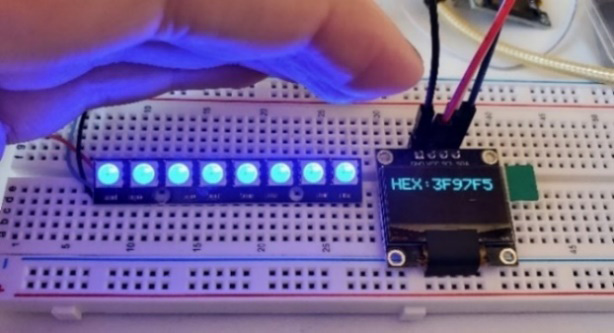
Figure 6.16 – The color sensor and two outputs – an OLED screen and NeoPixels
Then, the HEX code is written to the OLED screen, and the color is sent as RGB values to the NeoPixels (Figure 6.16). I’ve also checked the HEX code that was displayed on the screen and typed the value into a color HEX website, https://www.color-hex.com/, to check whether the value is close to what I’m expecting.
To make it into a wearable glove, you can sew the components to a glove that you already have. However, if you have some felt, you can use that to create a quick prototype fingerless glove. We just need a piece of felt big enough for our hand, front and back:
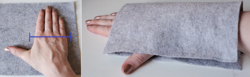
Figure 6.17 – Checking the size of the fabric
Place your hand on top of the felt, and measure across where your knuckles are. This will be the widest part of the glove. The material will need to cover that part of your hand and account for the thickness of your hand too. Figure 6.17 shows the area we need to measure, and the felt draped over the hand to be sure there is enough of the fabric.
Then, once you’ve cut the felt, fold it over your hand to be sure there is overlap to it so that it will fit once it is sewn (or glued) together. To start putting it together, it’s a good idea to use safety pins to hold the shape in place. Then, put the glove on to feel where the components will fit. Keep in mind that the purpose of this glove is for it to be used by someone typing on a computer because we want to help them with finding HEX code. So, make sure you can hold a mouse easily (Figure 6.18) when the components are on it.
Once you are satisfied with the placement, place the components on the felt and glue them into place:
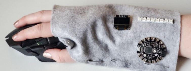
Figure 6.18 – Trying it before sewing the final version
The sensor is just out of view on mine because I want it near my pinky. Once the glue is dry, you can sew the components into place. I map out my connections before I sew to be sure I know where the threads might overlap. This rapid prototype in felt is a good way to test your wearable and find if there are usability issues.
I’m going to transfer my circuit to a glove design made from scuba style fabric neoprene for a stretchable fit. This would become a prototype iteration to test a more permanent solution because I like the functionality of this wearable!
Once you build upon your skill set, you may want to look at soldering NeoPixels yourself, which can be a great way to have the freedom to put these lights anywhere into a wearable technology garment (see Chapter 10, Soldering and Sewing to Complete Your Project).
Now that we’ve had a look at a complex circuit, let’s see how we can attach EL wire to a wearable.
Activity 6.2 – sewing EL wire
Adding EL wire to a wearable is a fun way to create an impact. It’s great to put on a backpack, for example, so that it can be seen at night. This could be a good idea for cyclists. You can add EL wire to an existing item or make a garment/bag and plan for the EL wire to go in the seam of it. Either way, it’s easy to do and only requires a few steps. To add EL wire to an existing bag, you’ll need the EL wire in the length that will work for you. You can cut it down to size, though. You’ll also need the inverter battery pack to power it.
Figure 6.19 shows an example of EL wire being sewn into a bag that I made by hand. The EL wire is sewn between all the seams as the bag was made. If you choose a simple shaped bag with light fabric, you can modify it by adding EL wire. You’ll need to choose a bag where you can open the seams easily and sew them back together again!
Turn the bag inside out. Using a seam ripper or small sharp scissors, gently pull up one or two stitches. Once you’ve cut through one or two, you’ll be able to tease the seam apart slightly. After you have a few inches of open seam, place your EL wire with seam into the gap. The EL wire should be on the outside of the seam, and the sewing tab on the wire should be between the pieces of the bag fabric, layering them together. Note that you’ll want to place the battery pack inside the bag to keep it safer and quieter:
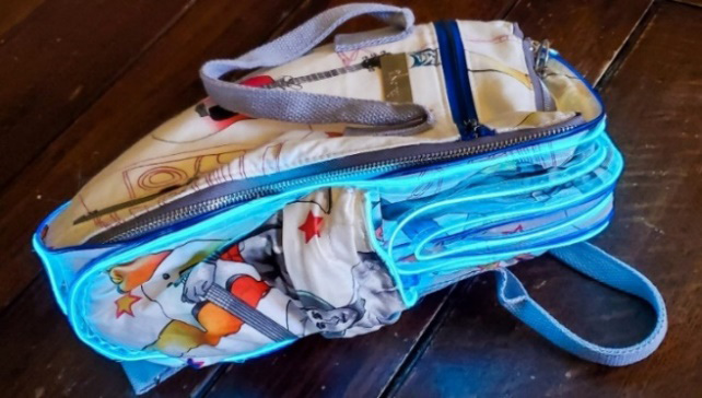
Figure 6.19 – EL wire sewn into a handmade backpack
Once your EL wire is in place, sew the seam together. This can be a great way to give an old bag a new life! What other garments or accessories can you modify? Think of the different colors and sizes of EL wire you can buy; this might help you create your own EL wire wearables.
A technology that focuses on connectedness, while not a wearable, is an application where this can be adapted, is BodyPods (Roseway, A., Dimitris Papanikolaou, D., 1999). It is “…a remotely paired set of communicating chairs that facilitate a sense of presence by leveraging implicit actions such as sitting to communicate that someone you care about is home.” This uses light for communication across distances and is a meaningful example of using light in alternative ways.
Now that we’ve looked at the different ways we can use light and vision, let’s learn about using sound as an output. Let’s make some noise!
Auditory – sound, tone, and audio
Sound can be an important indicator for the wearer, calling attention to potential errors, or for confirmation that something has happened. If we use sound effectively, we may not need to have a display for messages – if the tones are clear in their use. Understanding a person’s comprehension and interpretation of distinct sounds, pitches, and even the length of time a sound is emitted will enable effective communication. We can make interactions meaningful.
We can use buzzers and speakers (Figure 6.20 shows examples), though for more complex sound, there are MP3 boards that we can hook up to our circuits. We won’t be exploring MP3 boards as it’s a little outside the scope of this chapter, but it’s important to know that they exist. They can be great for providing better sound or communication through an audio file. It may provide a soundtrack to tasks or sensor input, for example. You may want to do some research about the types of boards that are available for sound, and what speakers and memory cards you need to use them:
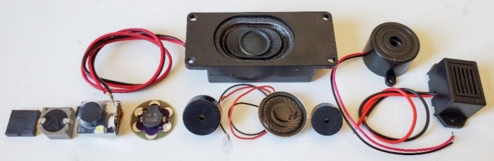
Figure 6.20 – A variety of piezo buzzers, speakers, and audio boards
If your wearable needs pre-recorded sound, you can use a sound FX audio processor board with bone conduction headphones so that only the wearer will hear it.
A passive or active piezo buzzer or speaker works similarly. Active usually has more height to it than passive and it’s sealed. The passive buzzer has electronics visible on the underside of it. It’s called active because it has electronics inside it. The passive buzzer will need other electronics to be used. The taller leg is the power side, while the shorter leg is for ground, just like an LED.
There is usually an indicator to show which side is positive as well, marked with a + symbol. If we connect the active buzzer, it will start buzzing right away because of the components inside. If we use the passive buzzer, we need to send a signal to it.
Buzzers produce simple sounds but many libraries exist that have tones. The example from Arduino (https://www.arduino.cc/en/Tutorial/BuiltInExamples/toneMelody) includes a file called pitches.h that contains pitch values, as shown here:
#define NOTE_AS2 117
#define NOTE_B2 123
#define NOTE_C3 131
When using sound in a wearable, it’s important to think it through and try it with other people. Their interpretation of the sound may not be the same as yours. Consider the following:
- What is the input that triggers the sound?
- What is the environment that it’s being used in? If it’s in a quiet place, people may not want a sound – vibration may work better.
- Is the sound for the wearer, or a warning for others around them?
- What sound will work best for your wearable?
- What location on or near the body will the speaker or buzzer be placed?
Let’s try a couple of exercises to get a buzzer working in a circuit so that you can hear the sound it makes.
Activity 6.3 – connecting and using sound
Connect a buzzer to the Gemma M0 board. Figure 6.21 shows the piezo connected with croc clips to Gemma M0 pin 0:
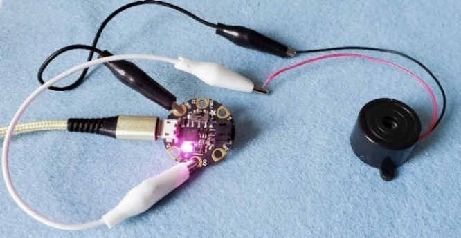
Figure 6.21 – Piezo and Gemma M0 connected
Choose the longer leg of the piezo, which is the power side (it might be marked with a + symbol), and connect it to pin 0. Then, connect the shorter leg, which is ground to GND on the Gemma M0 board.
The simplest way to check your buzzer is working is by using code to create a tone:
- No code is needed in setup()
- Type the code in the loop() function of the sketch: tone(1, 2000, 500);
The pin number is the first argument in the tone() function. The second number is the frequency, which is 2 kHz. The final argument specifies the amount of time we want the sound on. In this example, it’s half a second. Play around with these values to listen to other tones and durations. It’s a quick way to check your speaker and sound.
You can also use the following code for your buzzer, similar to the LED Blink code:
int buzzerPin = 0;
void setup() {
pinMode(buzzerPin, OUTPUT);
}
void loop() {
digitalWrite(buzzerPin, HIGH);
delay(500);
digitalWrite(buzzerPin, LOW);
delay(3000);
}
You’ll recognize we are initializing an int variable and have called it buzzerPin. We will use this to hold the value of the pinout that the buzzer is on. We define the pin as an output in setup(). Then, in loop(), we make the pin HIGH or LOW if we want a sound or no sound.
Now that we’ve used a buzzer that we’ve hooked up to a circuit board, let’s try the onboard speaker on the Circuit Playground Classic board.
Activity 6.4 – using the Circuit Playground’s onboard sound
The Circuit Playground board has a surface mount speaker. We used it for our touch sensor input in the previous chapter. Let’s look at a quick demo of using it with the two buttons on the board. The library for Circuit Playground allows us to get this working quickly. The speaker is connected to pin 5, and we’re using the two buttons on the board to control the sound. The left button is on pin 4, while the right button is on pin 19:
#include <Adafruit_CircuitPlayground.h>
void setup() {
 CircuitPlayground.begin();
}

void loop() {
 if(CircuitPlayground.leftButton()) {
 CircuitPlayground.playTone(440,100);
 CircuitPlayground.setPixelColor(3, 138,43,226);
 CircuitPlayground.setPixelColor(4, 138,43,226);
 }
 else if(CircuitPlayground.rightButton()) {
 CircuitPlayground.playTone(1760,100);
 CircuitPlayground.setPixelColor(6, 138,43,226);
 CircuitPlayground.setPixelColor(8, 138,43,226);
 }
Let’s take advantage of the many sensors the board has and use the light sensor to play music. This is a version of a light theremin that reads values from the light sensor – between 0 and 1023. We’ll use map again to map the input values so that they are within a playable and pleasant range:
#include <Adafruit_CircuitPlayground.h>
void setup() {
 CircuitPlayground.begin();
}

void loop() {
  uint16_t value, sound;
  if(CircuitPlayground.slideSwitch()) {
  value = CircuitPlayground.lightSensor();
  sound = map(value, 5, 1000, 131, 1760);
  CircuitPlayground.playTone(sound, 100);
  }
}
Now that we understand sound basics, let’s do another activity. Here, we’ll build a circuit that uses a sensor input and has a sound output, depending on the data received from the sensor.
Activity 6.5 – Touch Together – a socially playable instrument
Touch together, a game for social connections – it takes two to play this instrument! The way this wearable is designed is that you can’t touch the battery and the circuit together by yourself. I’m creating it out of neoprene fabric so that it is fitted but can stretch to a variety of sizes. I’ll use a zipper to close the forearm piece. The pieces that are needed for the circuit (Figure 6.22) include two pieces of large neoprene (or other fabric with some stretch to it) to fit around a forearm, a smaller piece of that fabric to hold the battery in place, zippers (or Velcro) to close the wearable around the arm, a Circuit Playground board, a battery, conductive fabric, glue, conductive thread, clips, pins, and an optional vibration motor:
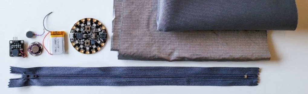
Figure 6.22 – Pieces needed to create this wearable
We’ll start by creating our two forearm pieces – one will have the battery and conductive fabric for the ground and power connections across to the circuit playground. Then, there are linked pads for the sound that you can play. This means we need the following:
- One forearm piece for the battery and conductive fabric pads for GND, PWR, and the pads for touch input.
- One forearm piece for the Circuit Playground board, GND, PWR, and pads for receiving the touch input from the other wearable piece, as well as an optional vibration motor.
Follow these steps to create this circuit:
- Measure out the neoprene for the forearm. Place your or a friend’s arm on a piece of paper or tissue paper. Wrap that paper around the forearm. Measure and allow extra fabric for placing the zipper/hook and loop edge and seams to sew. Also, make sure it’s not so tight that it stops circulation!
- Cut two forearm pieces from your neoprene.
- Once cut, check the neoprene’s shape. Wrap it around the forearm to make sure it’s sized correctly. This is a wearable that will be tried on and worn by many different people. With it being an alternative social musical instrument, it needs to fit a variety of arm sizes or cover various clothing thicknesses that someone might be wearing.
- I mapped out where the circuits would be placed on a spare piece of neoprene. This is so I can choose the flattest part of the arm and possible connections. Figure 6.23 shows this part of the process. You could do this on the paper from earlier:
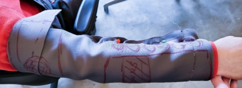
Figure 6.23 – Mapping on neoprene in situ
- Place the zipper/hook and loop on the fabric where it should be sewn according to your plans for zipper placement. Use clips/pins to hold it in place.
- Sew the zipper/hook and loop in place.
- Then, create the conductive pieces of fabric that will be needed. Plan for the touch inputs. If you are going to use all the touch pads on the Circuit Playground board, you’ll need 2x7 pieces of conductive fabric – one piece for each connection and then a corresponding piece to connect across the other piece of neoprene. I’m going to use a circle design, with two different sizes of circle pieces. This way, they will connect across the conductivity. You will also need two power, two ground, and various pieces for connections back to the circuit board.
You can cut out the shapes you want. First, I ironed double-sided Bondaweb® to the back of my conductive fabric (Figure 6.24). I used a Brother Scan and Cut machine (https://sewingcraft.brother.eu/en/products/machines/scanncut/scanncut-machines) to cut my shapes out (you can do the same with a Cricut machine: https://cricut.com/). The resulting cuts from the Scan and Cut machine give me consistent parts and takes less time than cutting:
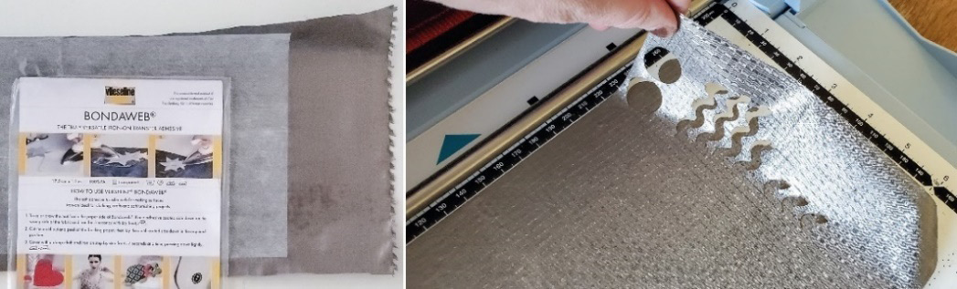
Figure 6.24 – Bondaweb® and the Brother Scan and Cut machine
Figure 6.25 shows the conductive fabric pieces after cutting. Cut them into any shapes that you want for your piece:
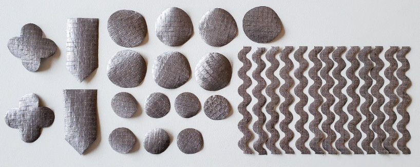
Figure 6.25 – Conductive fabric shapes for the circuit
Place the conductive fabric on the neoprene forearm pieces so that they will touch when two different people’s forearms come into contact.
Figure 6.26 shows how the connections will touch:
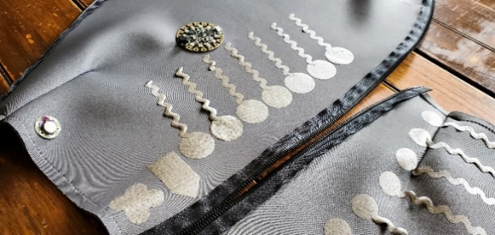
Figure 6.26 – Connections spanning across both forearm pieces
Measure the placement of your connections across both forearm pieces and hold them into place to ensure they touch before fixing them in place.
- When you have the conductive fabric pieces cut and ready, glue them into place. Don’t use too much glue because sometimes, it prevents us from sewing smoothly through the material.
- Take chalk and map out the circuit connections. This is where you will be sewing the connections, so make sure that none of the connections overlap.
Start sewing the connections! When the connections have been sewn, you’ll want to add a holder for the battery so that it’s secured. Make a snug pocket for it so that you can pop the battery in and it will stay in place:
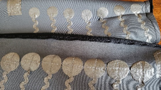
Figure 6.27 – The sewn connections
- Double-check that all your connections are snug. Secure all the ends with nail varnish (or fabric glue) and make sure none of the conductive threads are overlapping.
Once you have finished with all the sewing and making sure your connections are secure, we can upload the code.
This code will be the same that we used previously for our touch circuit, but we will add a tone and color sequence at the start so that we know we’ve made a successful connection when we touch forearms. Also, you should change the colors that light up; I’m altering this to have blue lights.
The code from Chapter 5, Working with Sensors: All About Inputs!, is available online at https://github.com/cmoz/Ultimate/tree/main/C5/C5_ConductiveTouch. You’ll need to add the following code to setup() if you’d like to have all the NeoPixels light up blue and with a tone playing when the social music maker starts. Why will the music only play on startup? Look at the following code:
void setup() {
 CircuitPlayground.begin();
  for(int i=0; i< CircuitPlayground.strip.numPixels(); i++) {
  CircuitPlayground.setPixelColor(I, ( 0, 0, 255));
  CircuitPlayground.strip.show();
  CircuitPlayground.playTone(984, 30);
  delay(40);
 }
 delay(1000);
 CircuitPlayground.clearPixels();
}
The code to play the music is in our setup(), so it will only play when the code initially loads. Once the code has been uploaded, pop in the battery and find a friend! Test this socially connected instrument out (Figure 6.28 shows the completed piece, worn by Xiang Li and Qiwen Sun):

Figure 6.28 – The friends-connected wearable in use
I hope you’ve enjoyed creating a fun wearable with a socially focused goal.
One final note: as with most wearable projects, using them will give you valuable feedback. This wearable activity is no different, and after use and observations, I noticed that it can be difficult to line up the conductive circles for the wearers. I decided to add magnetic buttons that repel if it is the wrong connection or attracts and “locks” into the correct positions. Figure 6.29 shows the magnetic metal snaps in place. They should be directly on the conductive fabric for where you want them to connect. You can see the opened and closed positions when two people wearing the sleeves are near each other:
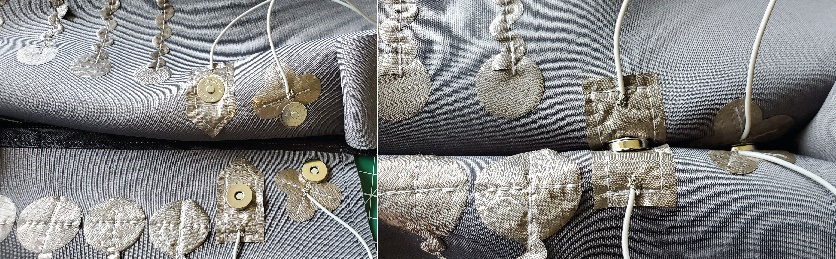
Figure 6.29 – Adding magnetic snaps – opened (left) and closed (right)
The outputs we’ve looked at so far have allowed communication through vision and sound. Lastly, we’re going to focus on haptic feedback while learning about motors and vibration for additional communication and interactivity.
Haptic – actuators, motion, motors, and vibration
I will admit, I used to avoid motors! I thought they were complicated to use. However, I’ve come to realize that using motion can create amazingly interesting pieces and is a lot of fun. Movement has a magical element when we see it, and it’s in our nature to try to figure it out. Why did a motor respond to our data? How did it physically create a reaction in response to data received? It’s exciting!
Haptic devices can deliver feedback to our skin and bodies. We can use our sense of touch as a form of communication. Does a motor vary in its intensity to give us information about a system? How about the pressure that we feel? Do we alter the duration and pattern of a motor based on our incoming sensor data?
These questions form considerations for our wearable projects. Haptic feedback can be a powerful way to communicate with visually impaired people, or for situations where a screen would be a distraction or hindrance.
Zhan, M. and Khan, A.A., (2022) created an obstacle avoidance system for visually impaired people:
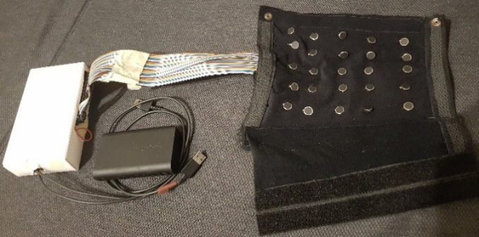
Figure 6.30 – Photo credit – Manuel Zahn, Inside the haptic sleeve
Part of their system uses a haptic feedback sleeve, as shown in Figure 6.30. They state that “The system is independent of lighting conditions and can be used indoors and outdoors. Therefore, the obstacle avoidance system demonstrates a promising approach to using technology to enable more independence for the visually impaired.”
Another multi-object recognition system for the visually impaired can be made using off-the-shelf components like we are using. Park, H., Ou, S., and Lee. J. (2021) prototyped an object recognition system to allow people with a visual impairment to walk safely when alone.
Not only can movement help with communication, but some projects explore other ways to use motors and motion. One beautiful example (Figure 6.31) I came across was Finger Orthosis – a prototype for energy harvesting through movement as an alternative power source, by Franziska Kinder. This uses a stepper motor with gears. For more information, visit https://www.whoisfrancis.de/ Kinder says, “…about sustainability, I prefer to work transparent and open source. Projects should be easy to reproduce, and the technology should be understandable as well,” which is a great ethos for wearable projects:
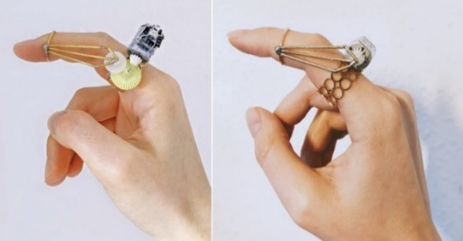
Figure 6.31 – An elegant motor prototype. Photo credit – Franziska Kinder
So, how can we add haptic, touch, or feeling to our wearables? There are several ways to add touch elements.
We’ll investigate the following:
- DC motors, vibration, and fan (axial motor):
- Heating pad
- Servos – 180, 360, and continual rotation
- Linear actuators
Motors, servos, and fans all have similarities as they all have movements. Looking at Figure 6.32, we can see the different forms they take. A heating pad has also been included because we feel the temperature heat up with this component:
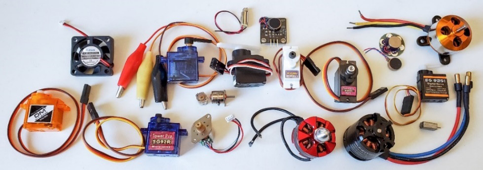
Figure 6.32 – Varieties of feeling output, servo motors, axial fans, and vibration motors
We’ll begin looking at each of these areas in a general way so that we understand how we can integrate them into our wearables. We’ll follow that with activities so that we can integrate them into our circuits.
DC motors, vibration, and fan (axial)
A direct current (DC) motor is fairly common and will be included in most standard Arduino kits you buy. They have two wires – a ground and a positive. When connected, it will rotate. Typically, a driver circuit will need to be used to power the spikes of power a motor uses.
In wearable designs, small vibration motors are often used. This is a DC motor with a weighted part that moves when the motor spins. There are different types of vibration motors, so always check the size and if the weighted part is internal. If you think about your mobile phone, you may have it set to vibrate for notifications. We can buy similar small vibration motors to have the same vibrations in wearables to alert the wearer in some way.
Some projects and research that have used vibration for communication include the following:
- Alerting visually impaired people of their surroundings
- Communication between people over distances
- A belt for children with hearing impairments to feel feedback
- A glove for haptic sensations during movies
- Notifications and positive feedback
- Heartbeat communication for wearers or family
- Posture monitoring systems
Vibration is also good for confirming input, for example, on a keypad or number pad. I’ve used vibration motors as positive feedback for when a wearer performs an action. You may have vibrations turned on when you type on your mobile phone for example. It can save a person time if they sense the feedback immediately, rather than looking to a screen to see confirmation of this. Also, it can be discreet enough that only the wearer is aware of it. A vibration motor can be a good solution for designs where you don’t want a sound as an alert. However, if they are placed near or against other things, they can be noisy, so plan and map out your circuit and test it. Harder items amplify sound, while softer materials absorb it.
Webster (2000) prototyped a fingertip search device for visually impaired people. It used an 8x8 array of motors and its primary aim was to allow for research into the importance of fingertip exploration. This early work helped the field gain important knowledge about feedback systems. Another vibration system is a project that Stanford researchers are collaborating on. It’s a vibrating glove they are testing, to help improve hand function after a stroke. Figure 6.33 shows such a prototype:
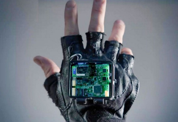
Figure 6.33 – Haptic prototype for hand function after a stroke
Georgia Tech graduate Caitlyn Seim started the project. She hoped that the glove’s stimulation may have a similar impact as more traditional exercise programs. She developed an early prototype as a proof of concept. More information is available online at https://neuroscience.stanford.edu/research/funded-research/pts-glove-passive-tactile-stimulation-stroke-rehab-renewal. These projects and research are only a few examples of the ways we can use motors in real-world situations.
Let’s start our journey and connect a motor.
To hook up a motor, you’ll need the following components:
Figure 6.34 shows these components. I’ll connect them to a breadboard to show the connection when using these types of motors. I’m trying this circuit with two different DC motors, so there are two in the following figure. The one in the square housing is called an axial fan. We will use the axial fan in a later activity; it connects in the same way, so the motors are interchangeable:
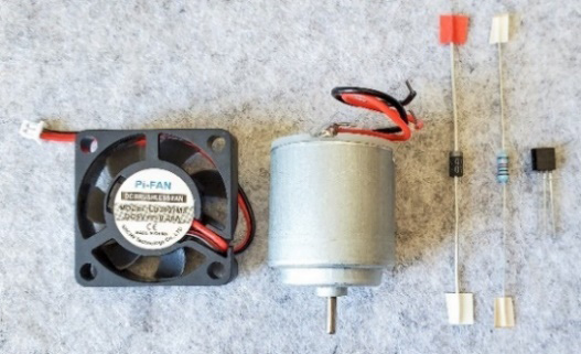
Figure 6.34 – DC motors for a circuit, a diode, a 270 Ω resistor, and a transistor
Considerations for an axial fan include the supply voltage, fan speed, and noise levels. Again, check your datasheet for details about the component you are using. You may also consider the shape, which is typically square, as shown in Figure 6.34, or circular. Usually, axial fans are used for cooling. They are the types of fans we have in our computers for example. The connection for a working DC motor is shown in the following diagram (left) as well as the photo (right) in Figure 6.35. An important part of the circuit to be aware of is that the transistor, which has three legs, should have the flat side facing into the circuit:
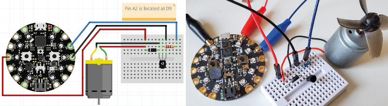
Figure 6.35 – Motor components connected
This flat edge is visible in Figure 6.35, where you can see the connected components. The transistor has three pins, with the flat edge facing you:
- The left leg is for the ground connection to the circuit board.
- The middle leg is where the resistor is connected. The other end of the resistor connects to the pin on your board, so in my example, I’m using A2 (D9).
- The pin on the right is where the diode starts, which is also connected to the ground connection on the motor.
- Lastly, the other side of the diode connects to the power or both the circuit board and the motor.
Check your circuit before connecting your board to your computer. I’ve connected mine to a Circuit Playground board in this example.
Important Note
The 1N400 diode has polarity, meaning it must be inserted in the correct direction. This allows the current to flow in only one direction – that is, toward the silver marking. So, check and double-check that yours is the correct way around.
Using a motor with an Arduino based board is easy to implement. The following code allows a motor to be turned on:
int motorPin = A2;
void setup() {
  pinMode(motorPin, OUTPUT);}
void loop() {
  digitalWrite(motorPin, HIGH);
}
The preceding code uses the same code that we used for our LED, in that we turn on the pin that the component is connected to. We are sending the voltage to that pin, and this will turn on the motor.
To add feeling as an output, you can use a heating pad (Figure 6.36). It uses the same code and circuit setup as the one we’ve just used. Swap the motor out for the heating pad to add warmth to your wearable. Electric heating pads are thin and slightly flexible.
You can add them to wearables for a mild heat sensation. The heating pad uses the same circuit we created for the motor, with a transistor, diode, and resistor. We can sew a pocket for this pad and then use it in a belt circuit to help if we suffer from back ache:
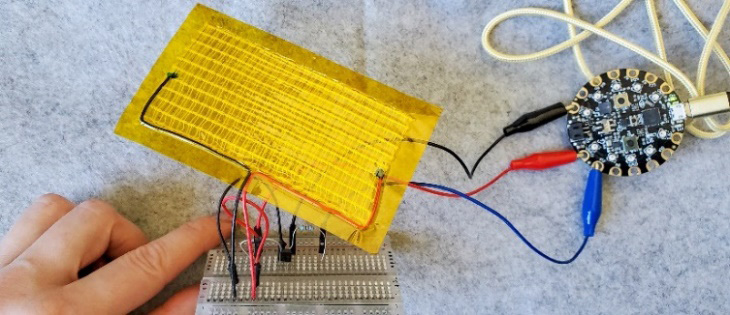
Figure 6.36 – Heating pad
A stepper motor is usually described by the number of steps that happens per revolution. The ones usually included in Arduino kits are 32 steps, with the gears inside of the motor housing. It is capable of 513 steps (32x16). It will do a full rotation in equal steps. You may have seen larger versions of these motors on 3D printers, for example, as they are great at making precision movements. Also, note the voltage that this motor will use because you will likely need a driver board. It uses the Stepper.h library. You can change the number of steps per revolution, choose the pins your motor is attached to, and then set the speed in the setup() function of the sketch. In the loop() function, you can control the revolutions – clockwise or counterclockwise. There are sample sketches in the library; it’s a good idea to open them and have a look through the code.
Other types of motion can be made with servos. Let’s take a look.
Servos – 180, 360, and continual rotation
Servo motors can be programmed for very specific positioning. These are accurate positional types of movements. There is a set of gears that rotates to the number of degrees that we define in our sketch. Some servos will move 0 to 180 degrees, and you can also get 360-degree servos or continual rotation servos. In Chapter 5, Working with Sensors: All About Inputs!, we connected a Flora board with a servo motor that was controlled by touching a leaf; it was shown in Figure 5.39:
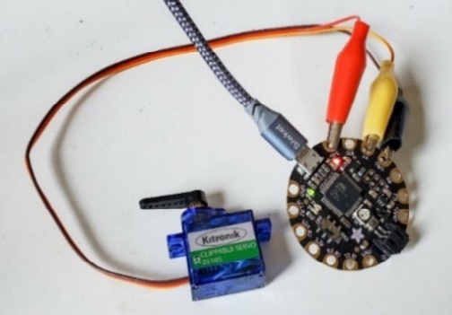
Figure 6.37 – Servo with croc clip connections
One of my favorite servos for prototyping is the servo that has croc clips (Figure 6.37) for connections.
For this, you can use the Servo.h library. There is a sketch in the Arduino examples folder called Sweep that shows the 180-degree movements. You can add more than one servo to your wearable and be on the lookout for some of the smaller versions, which can be great additions to projects.
These servos usually perform sharp, quick movements, and they can be noisy too, so you will need to figure out how they should be placed in your wearable. It’s a good idea to play around with them, get to know how they move, and discover what is most appropriate for your circuit. You could use them to move parts of your garment or move things that are placed on it. They can be used to create stunning and dynamic pieces that shift and move in deliberate ways.
Linear actuators
A linear actuator pushes or pulls something in a straight line. You can find some very small linear actuators that can be embedded in your wearable projects. It may move something in a straight direction for effect or connect other parts of your circuit. They have two wires – ground (negative), which is usually black, and power (positive), which is usually red. These motors keep their positions when the motion is stopped while extending or retracting. Look for the lower voltage linear actuators so that your circuit board can power them.
Overview
With all these motors and movements, you can use the input as data to control your motor. We can use sensors to control the output. This is why we looked at sensors first. It’s worth spending time exploring the varieties of motors, specifically for the following purposes:
- Weight
- Size
- Shape
- Features
- Voltage requirements
Understanding these properties will help you when you plan your wearable. You’ll understand what components are available and how they can be controlled to add those important interactive elements to your projects.
Now that we have read about these motors, let’s make a wearable circuit!
Continuing our journey into haptic feedback, we’ll make a circuit that uses a sensor for input and with the data received, a reaction will be made by the appropriate output. In this instance, sound and vibration will be used as alerts.
Activity 6.6 – haptic feedback with a UV sensor
Putting a sewable UV sensor on a hat is sensible. We wear a hat to protect ourselves from the sun and skin cancer is often caused by overexposure to the sun. This can help reduce our chances of getting sunburnt and of exposure to harmful UV levels since it alerts us with a sound to remind us to put on sunscreen. We’ll also use a color reference, similar to what’s used in UV charts. The one shown in Figure 6.38 shows the lowest level at 1, which is green, to the extreme level of 11+, which is a harsh red:

Figure 6.38 – UV light level indicators
We will connect a UV sensor and when the UV sensor detects a high reading and it reaches dangerous levels, a buzzer will make a noise and the NeoPixels will change color to alert the wearer to apply more sunscreen lotion.
For this circuit, we’ll use the components shown in Figure 6.39:
- A Circuit Playground Classic (with vibration or a standalone vibration motor)
- A sewable UV sensor, though you can use other UV sensors and sew them
- Conductive thread
- A battery
- A cap/hat
Note that you could use a Gemma M0 but I’d like to add additional outputs and functions to this activity, so I’m going to use a board (Circuit Playground) with more outputs:

Figure 6.39 – Items used for this wearable
First, let’s map out the circuit. As we’ve seen previously, we will connect the UV sensor using the I2C protocol. To make this circuit, we will connect the UV board to the Circuit Playground board. Connect the following:
- UV board SDA pin to Circuit Playground SDA
- UV board SCL pin to Circuit Playground SCL
- UV board GND pin to Circuit Playground GND
- UV board PWR pin to Circuit Playground PWR
- Vibration motor GND to Circuit Playground GND
- Vibration motor PWR to Circuit Playground pin 1
I’m using croc clips again for the prototype to be sure it works. I’ll upload code at this point to check my connections are correct and working before I sew it all in place:

Figure 6.40 – Using the fold for the battery
Position the components on the hat with the UV sensor facing upwards toward the sky. Place the Circuit Playground and battery where they will be comfortable for the wearer (Figure 6.40 shows the battery hidden in the hat’s underside). Glue them down to make it easier to connect them (Figure 6.41). I used a glue gun to make a strong bond:

Figure 6.41 – Gluing the components into place to make them easier to connect
Let’s add the code. Open the Arduino IDE and connect your Circuit Playground. We already have the UV library installed from Chapter 5, Working with Sensors: All about Inputs! , but if you didn’t grab it, then you’ll need to open the Library Manager and search for Adafruit_SI1145 library. Once installed, open the sample si1145test file and upload it. Check that you have your Board and Port chosen. Open Serial Monitor to see if your program output is correct. The test code checks the UV sensor and if it is working. We want to add sound, vibration, and light to it. The complete modified code can be found at https://github.com/cmoz/Ultimate/tree/main/C6/C6__UV_ColorVibration.
Let’s look at a snippet of the code.
In the code, look for the if statements and conditions that have been set. The first one defines that the reading should be larger than the threshold we set. This is the threshold for an indoor reading. If the reading is higher than the indoor reading and it’s smaller than a value of 689, then the UV levels are low. It will color the NeoPixels a blueish color.
Looking at the next if statement, we can see that the values are higher, so we defined it as moderate UV levels. We created a yellow-colored NeoPixel, set a vibration as an alert, and set a tone to play to warn the wearer:
if(uv.readUV()>= UVthresholdIndoors && uv.readUV()<689 )
{
 Serial.println("LOW");
 neoColor(0,255,100);
} else
if(uv.readUV()>=690 && uv.readUV()<1379)
{
 Serial.println("Moderate");
 CircuitPlayground.playTone(345, 200);
 neoColor(255,191,0);
digitalWrite(vibePin, HIGH);
} else
Once the code has been uploaded, test your circuit outside. Note that values won’t register if you use the UV sensor indoors. The completed cap is shown in Figure 6.42 with an indoor and an outdoor reading:

Figure 6.42 – The completed cap – sensing UV
This has been a fun and important wearable for our skin’s health. We incorporated a sewable UV sensor to help parents, caretakers, or ourselves know when we need to put on sunscreen. However, we can take this an extra step forward. In the next activity, we’ll look at how the temperature can also affect our wearer.
We are going to use the onboard slide switch to add more functionality to our cap. If we slide the switch one way, it will run the UV code, but if we slide it the other way, it will run a temperature check. Let’s complete the next activity to see how this works!
Activity 6.7 – using temperature and motion
We will continue with the last circuit, but this time, we will use the slide switch (see Chapter 2, Understanding and Building Electronic Sewable Circuits, for more information about switches) to control which program we want to run:
- Sliding the switch to one position, we can use our cap outside for UV sensing, which we just completed: the outdoors cap.
- Sliding it to the other position, it will use the temperature sensor for when the cap is worn indoors. When a certain temperature is reached, it will turn on a fan that will blow air to cool us down: the indoors cap.
The Circuit Playground board has a temperature sensor built-in, so we need to access it.
First, we need to add the circuit for the axial fan. The circuit has a fan, diode, transistor, and resistor. These can be sewn on a piece of felt. Refer to the circuit shown in Figure 6.35 on the breadboard to check that you are putting the components in the correct place, then curl the ends of the components, as we did in Chapter 2, Understanding and Building Electronic Sewable Circuits, to make these components sewable.
The axial fan is connected to pin A1 in the code, which is marked as TX1 on the Circuit Playground Classic board. The servo is connected to pin 12. The servo is used to move the fan into position. It’s an optional part of this circuit, but it makes it look very cool!
Then, I glued them into place (Figure 6.43) to make them easier to sew. Remember, when using conductive thread, don’t overlap any of these connections!
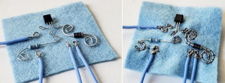
Figure 6.43 – Sewing the diode, transistor, and resistor
For adding the servo, a little clip-on hinge (Figure 6.44) was made for this circuit by Fergus Fullarton Pegg. It was designed in Fusion 360 and printed using TPU on a 3D printer. This is to connect the fan to the brim of the cap:
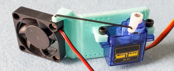
Figure 6.44 – Servo/fan mount with a hinge for the cap
You could glue the 3D hinge in place/sew it or mount it in another way. I wanted a hinge so that the servo could move the fan if the temperature changed. The final one was printed in a darker blue to match the cap. You can place your fan onto the cap by gluing the servo to it, and then glue the fan to the moving part of the servo.
Append the code so that it includes the functionality we’ve added:
- The switch feature of the Circuit Playground (to select our program)
- Temperature
- Servo
You can access the code with this functionality at https://github.com/cmoz/Ultimate/tree/main/C6/C6_UVBuzzTempMotion.
The completed cap is shown in Figure 6.45, with the fan added to our original circuit:
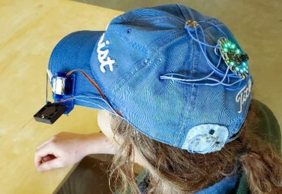
Figure 6.45 – The completed cap
Working iteratively is how you might start creating wearable projects. We start with one feature, then build on it. Working iteratively allows us to increase the complexity of our circuit in a way that we can still find errors as they happen. If we had just put everything together at once and then tried the code, chances are that there would be a few errors – at the least! We will investigate building up projects in more detail in Chapter 9, Designing and Prototyping Your Own Hyper-Body System, and Chapter 10, Soldering and Sewing to Complete Your Project.
Summary
This chapter worked you through some difficult circuits that implemented both the inputs and outputs that we’ve been learning about. Through the exercises, we increased complexity in our circuits, to help us to understand how to build complexity in wearables that can serve a purpose. As we progress through this book, the way to make and consider social conscience wearables will become clearer, and I hope that thinking about wearables in this way motivates you to also consider the purposes behind the wearables you make.
Some of the pitfalls when using different outputs is that we need to be aware of the I/O pins we need and select an e-textile board that will suit our needs. This sometimes means that we must compromise on the size or shape of the wearables we make. Also, sometimes, these added complexities add to the code complexities. This will take time and practice to get right but there are a lot of forums and resources available for you. Arduino is a good place to start (https://support.arduino.cc/hc/en-us) and, as mentioned previously, there are great resources on Adafruit (https://learn.adafruit.com/), Proto-Pic (https://proto-pic.co.uk/), and Kitronik (https://kitronik.co.uk/), to name a few.
When using NeoPixels, be aware that you can have voltage drop issues. Along some of the longer NeoPixel strips, you may have seen multiple power in points (solder tabs). You can connect power and ground at multiple places along the strip to be sure it has full power all the way along it. This can sometimes fix low brightness and flickers. Additionally, when creating circuits that are a bit more spread out in distance with components, the conductive thread may start to lose its effectiveness. You will have to start thinking about soldering some circuits to create more permanent connections. Luckily, we have Chapter 10, Soldering and Sewing to Complete Your Project, coming up!
Having a variety of outputs to communicate to the wearer gives us many options to suit many people. We can design accessibility and inclusivity into the designs by using different modalities such as vibration or bright light.
Now that you have completed this chapter, spend some time reflecting on the types of wearables you have seen or read about and how they can be inclusive.
- Are there designs that you could implement different outputs in so that they would suit a wider audience?
- Have you seen products that are too exclusive because they don’t communicate effectively with a wearer?
- What designs would you like to implement, and for what types of people? It would be great to make some notes, drawings, and collections of things you have seen so you can refer to them later when your confidence grows and your ambitions to create larger projects can be fulfilled.
Now that we have our inputs from the previous chapter, and our outputs from the one we’ve just finished, it’s time to build on that knowledge and get busy making! We’ll explore an exciting integrated circuit called the ESP32 and some of its varieties in the next chapter.
References
The following references were provided in this chapter:
Schmidt, A. (2000). Implicit human computer interaction through context. Personal technologies, 4(2), 191-199. [Available online] https://www.researchgate.net/publication/2532959_Implicit_Human_Computer_Interaction_Through_Context.
Ju, W., & Leifer, L. (2008). The design of implicit interactions: Making interactive systems less obnoxious. Design Issues, 24(3), 72-84. [Available online] https://www.researchgate.net/publication/249563448_The_Design_of_Implicit_Interactions_Making_Interactive_Systems_Less_Obnoxious.
Papanikolaou, D., Brush, A. B., & Roseway, A. (2015, January). Bodypods: designing posture sensing chairs for capturing and sharing implicit interactions. In Proceedings of the Ninth International Conference on Tangible, Embedded, and Embodied Interaction (pp. 375-382). [Available as a PDF online] https://d1wqtxts1xzle7.cloudfront.net/38570953/tei275-papanikolaou-brush-roseway_light-with-cover-page-v2.pdf.
S. F. Frisken-Gibson, P. Bach-y-Rita, W. J. Tompkins and J. G. Webster, A 64-Solenoid, Four-Level Fingertip Search Display for the Blind, in IEEE Transactions on Biomedical Engineering, vol. BME-34, no. 12, pp. 963-965, Dec. 1987, doi: 10.1109/TBME.1987.325937.
Zahn, M., & Khan, A. A. (2022). Obstacle avoidance for blind people using a 3D camera and a haptic feedback sleeve. arXiv preprint arXiv:2201.04453. [Available online] https://arxiv.org/pdf/2201.04453.pdf.
Park, H.; Ou, S.; Lee, J. Implementation of Multi-Object Recognition System for the Blind. Intell. Autom. Soft Comput. 2021, 29,247–258 [Available online] https://www.researchgate.net/publication/351719067_Implementation_of_Multi-Object_Recognition_System_for_the_Blind.
Review questions
Answer the following questions to test your knowledge of this chapter:
- How many wires does the I2C protocol use and what are they?
- What is the golden rule when making circuits so that you don’t accidentally burn out your board?
- What does the strip.setPixelColor(4, (0, 0, 220)); line of code do?
- What are some of the ways we can use light and vision in our wearable?
- What useful purpose does the switch on the Circuit Playground board have?
- What additional components do we need to add to our motor circuits to make sure the motors work?
- Reflection: Which outputs did you enjoy the most? What planning can you do to use these different visual, audio, and haptic communication methods with the wearer? Take some time to think about some of the communication methods you’ve seen in existing products or items. What did you find effective, annoying, or unusual? Could you swap one output for another? How would that affect its use?