
9
Designing and Prototyping Your Own Hyper-Body System
What is a hyper-body system and how can we make one? We will focus on designing and building low-fidelity and proof-of-concept prototypes for your hyper-body system, using components and microcontrollers suitable for your fashion tech item. This chapter will help you to choose the appropriate components for your purpose and to test your circuits. These are essential skills for creating working wearables and fashion tech pieces.
In this chapter, you will be consolidating the knowledge you’ve acquired in previous chapters to create a wearable technology project that is ambitious and exciting. We will learn about hyper-body systems and how to design one. Then, we’ll do some project planning and jump into an ambitious wearable using the Internet of Things (IoT).
By the end of this chapter, you will have completed a project that can be controlled by friends or family through the internet, and you will have your circuit ready for sewing into a wearable. You’ll have learned many exciting new concepts that will help you to continue to advance your skills and create projects with wearable interactions that go beyond our desktops.
In this chapter, we’re going to cover the following topics:
- What is a hyper-body system?
- How to design your hyper-body system, choosing materials, components, and purpose
- Building up your prototype – function by function
- Connecting the QT Py to the internet
Technical requirements
This chapter is about learning how to make more use of the ESP32-based boards we looked at in the previous chapter. We will continue our journey using a small but capable board for our project in this chapter. We will need the following:
- Arduino software as the IDE and access to https://io.adafruit.com/.
- An Adafruit QT Py ESP32-S2 (you can use -S3 or the Feather HUZZAH from previous activities).
- NeoPixels of your choice, a heating pad, and a vibration motor.
- You will also need a 1N4001 diode, a 270 resistor, and a PN2222 transistor, breadboard, and hook-up wires.
What is a hyper-body system?
Connecting three or more of the five basic senses would be considered hyper-body. We connect senses and materials by enhancing these senses or substituting them. The basic human senses are considered to be touch, sight, hearing, smell, and taste. Our body senses these and sends information to our brain to process the messages to help us perceive the world around us. Some sources consider some additional senses to be spatial awareness (proprioception and body awareness) and balance (equilibrioception) because we also couldn’t live without them. You may see these terms referred to slightly differently, such as the vestibular sense or movement. Acceleration, time, pain, temperature, and kinesthetic senses are also sometimes discussed. Humans are complicated systems!
Touch is considered important not only for survival, for example, knowing to not get burned by fire, but also for communication. Compassion from others that we can sense through touch can contribute to our positive mental wellbeing. Our sense of touch can be described as different sensations registered through the skin. These include pressure, temperature, and touch variance – incorporating the sensation of air or wind, vibration, and pain. Textures sensed through our touch can help us to understand concepts and tactile sensations can alter the products we buy, based on how they feel. When I make wearables, I am aware of the wires I choose so that they are not only very flexible if I use silicone-covered wire but they also feel soft to the touch and don’t restrict movement. I enjoy working with this material because of its specific physical properties.
Sight is very complex, so I won’t go through how our eyes process sight – that is beyond the scope of this book. However, our sense of sight is very important to us for understanding information including color, color variance, the brightness of lights, and sensing motions or dangers. We interpret an enormous amount of information continuously and so it can also be important not to overwhelm this sense with unnecessary information. Also, for people with a visual impairment, it is essential to consider how our designs and wearables can be altered to be inclusive.
Hearing involves sounds being sent to the inside of our ears through an auditory canal to reach the eardrum, which is a thin sheet of tissue that vibrates with sound waves. Further through the eardrum, eventually, there are tiny hair cells that turn the sound waves into electrical impulses that travel to the brain. We also retain our sense of balance because the ear equalizes the pressure in the middle of the ear with the pressure in the atmosphere. Again, this is all overly simplified just for the purposes of a basic understanding. What we are concerned with is the auditory cues that we can get through beeps and tones as affirmations of events happening or that have happened. Sometimes, we may send a sound to confirm that something has been activated or turned on, or an action completed. These cues are all important to the understanding of our wearable system. Again, it is essential we make our wearables accessible and inclusive and be mindful of someone with a hearing impairment and how they might interact with a system. This can also be seen as an opportunity. The Quietude Project (Wilde, D., Marti, P., 2018) develops wearables with this in mind, "using experimental participatory design methods, and the value of considering disability as an opportunity for wearables design, rather than as an issue that needs to be addressed or solved."
Smell happens through the olfactory cleft, which translates smells to our brain. We can detect 1 trillion odors using 400 smelling receptors. Smell is the quickest of the senses and is closely linked with our memories. It can be a trigger to our childhoods or an emotional experience. It can also be used for relaxation purposes or pleasant experiences via perfumes and other smells – or make us feel hungry when we smell fresh foods. It can also be a personal, emotional response in terms of personal body odors when we are near family, friends, and other loved ones. Smells can also alert us of dangers, such as fires, rotten foods, or chemicals.
Taste can often be combined with sight in terms of seeing the things we eat, as well as with touch, given the way that food feels in our mouths – the texture. Taste helps people identify what could be poisonous due to bitter or unpleasant tastes. The smell of our food also affects the brain’s perception of taste. Some people also test whether a 9V battery has charge in it by touching it with their tongue. I’m not recommending it, but there is a buzz sensation on the tongue that tells us there is still charge remaining.
Other senses mentioned include awareness of where we are in space, as well as balance. We have a sense of movement and the positions parts of our body are in and where they are located. Can you touch your nose with your fingertip while your eyes are closed? This is the understanding of where we are spatially. Exploring existing technologies in creative ways to capture movements was the focus of Hedy Hurban’s research in 2021. Focusing on cultural performance wearables, she focused on "a wearable device that can be attached to clothing or held in the palm of the performers hand and used as an extension of the body or a wearable musical instrument." The Sound Drop device was created to augment a body for movement in performances (see Figure 9.1):
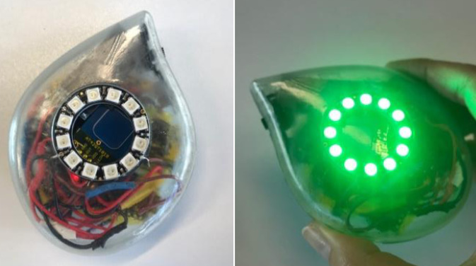
Figure 9.1 – The Sound Drop augmenting the human body in cultural performance
Whatever senses we focus on, it is the body that plays an important role. How can we connect our senses and materials using technologies and ourselves in this hyper-system?
Flex-N-Feel are emotive gloves for couples that support touch over distance. Singhal, S., Neustaedter, C., Ooi, Y. L., et al. examine the challenges of long-distance relationships in their work from 2017. They consider not only personal or intimate relationships but also work and educational systems as well. Earlier research also looks at this issue – Gooch, D., and Watts, L. authored It’s neat to feel the heat: How can we hold hands at a distance? in 2012 for investigating communication technologies that support long-distance relationships. Even earlier than that, Hug over a Distance was a study regarding close relationships who are separated by distance and how can they express intimacy (Mueller, F. F., Vetere, F.,2005). Other mood, emotion, or wellbeing works include sweaters that interpret excitement levels and illuminate a collar in response (a GER mood sweater) and using a soft sensor that reads electrodermal activity (similar to a lie detector test). Also, keep in mind the wrist-worn devices that monitor everything from motion to sleep and stress metrics that record our everyday activities.
Now that we’ve had a look at some of the senses and thought about how they might inform design, let’s learn more about designing our own hyper-body wearable.
How to design your hyper-body system – choosing materials, components, and purpose
We’ve completed several activities throughout the book and they have become increasingly complex. In this section, we’ll look at designing your own hyper-body system and what you should consider as part of your wearable design process.
The many forms our wearables can take include socks, vests, underwear, scarves, wristbands, gloves, hats, belts, jewelry, and near-body items such as purses, handbags, and backpacks. How will you choose the form for your project? Making decisions about how to protect or secure your circuitry for a wearable is an important factor to think through as part of your planning. In a hyper-body system, we may have sensors or outputs in several locations. This has an impact on their placement too.
As the complexities of our circuits increase, you may decide to move from the typical placement of components on top of the fabric to a more incorporated and hidden design. Figure 9.2 shows one on top of the surface and a more hidden placement design. This may move further away from a clunky circuit board to integrating it into the fabric as part of the design:
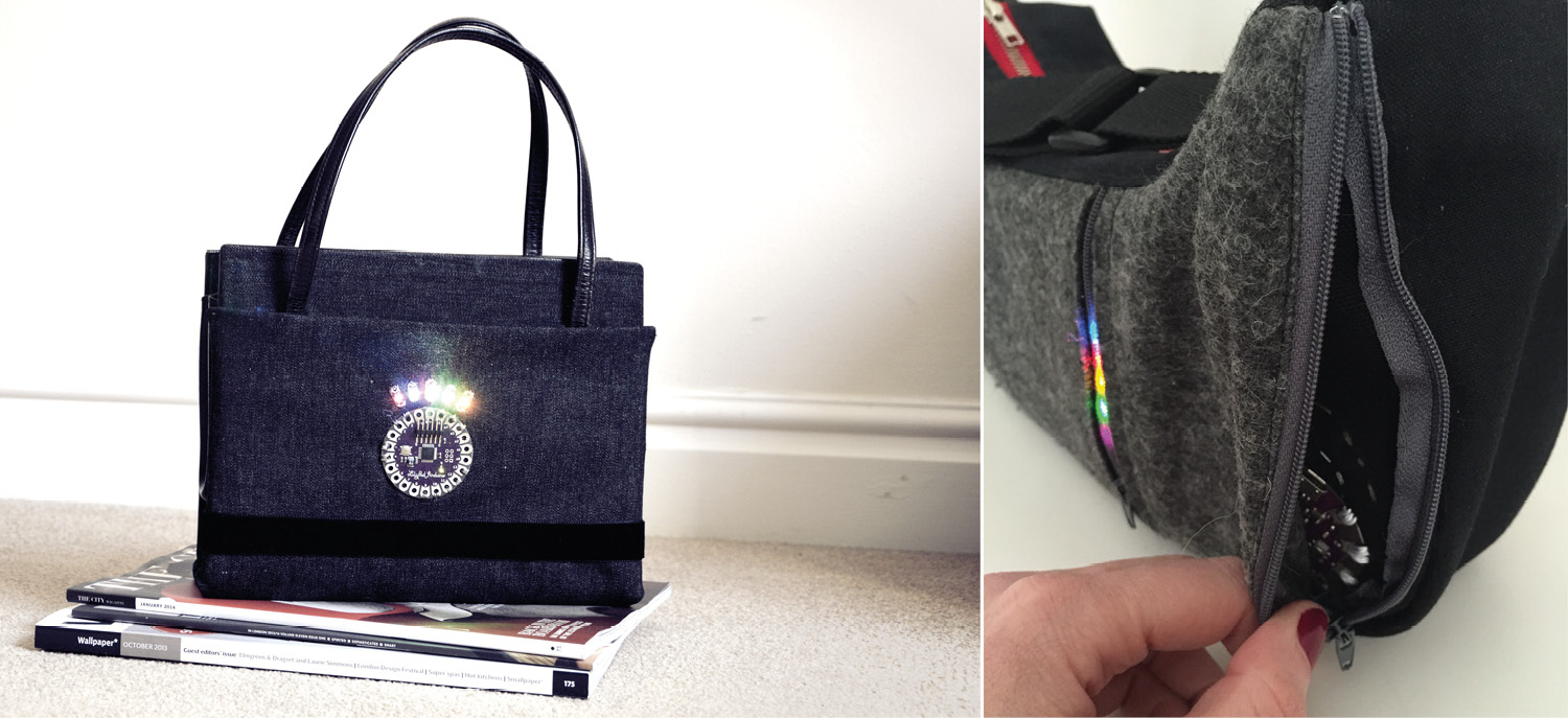
Figure 9.2 – Electronics on show and hidden
Our clothes have been designed from several pieces of fabric, which works out well for us. It means we can pick them apart to get access or add to them. We can use the clothing already created as our canvas, which we can modify, and doing this usually gives us a lot more time to prototype our circuits too. This is useful in the early stages of our wearable practice when we are creating a proof-of-concept piece or a low-fidelity prototype. Once you move beyond the first prototype and have specific requirements, then sewing the garment itself is also an exciting part of the process. For now, keep in mind hacking open those seams, zippers, pockets, and linings – rip it all!
Mini challenge
Spend a few minutes to look at some of the clothing in your home. Tops, jackets, boots, gloves, and more all provide opportunities for projects. Where could you place your components? Where would wires or electronics even enhance the item?
Try to look for thicker fabrics if you’re at a secondhand shop. These can provide a little more stability, especially if we need to put a heavier component or battery pack in there. Hoodies, jackets, and jeans all provide a great base for your designs. Also, ripping the seam is a great way to get a wearable inside, but you can also add pockets or folds of fabric on top of the item of clothing. Maybe the clothing item is thin – could you add a lining to it that will give your wearable stability?
Keep an eye out for different types of textures, too. Is one faux leather or wool, and another canvas or denim? Having an open mind to creating with different materials can free up your designs. Don’t forget sleeves on a top that you no longer wear can turn into two different forearm or full arm pieces, or even just bands of wearables that you then use a zipper or poppers to connect.
The purpose of your wearable will also dictate some of the fabrics or garments. Will it be for a child? Is this a wearable for a group of people – firefighters, for example, who will have very particular needs? Get to know who you are designing for and what the primary purpose will be. This will make your planning useful and accurate. Let’s learn a little more about planning.
Understanding the importance of planning
Choosing components can affect your circuit’s placement, comfort, and size – look for flat backs on components and how far things might stick out. Planning when making your wearable will save you time and errors. A few tips include gathering all your components together and really looking at each one to decide how it can be placed or accessed. What if there is a problem with the component or connection – will you be able to access it easily? Can you swap it out if something goes wrong?
Planning a back door
Do you have power needs or components that might need changing, and if so, can you get to them quickly and easily? Try to include a flap or a way to get to the components if you need to. I’ve had a wearable completely crushed, unfortunately – I had to open it up entirely and it created a lot more work for me than if I’d just sewn in a zipper or Velcro flap, for example, so I could get at the components more easily.
Place your components on the body part where you want to use it. Does it sit how you want it to? Make sure you don’t restrict movement or make it awkward for the person wearing it. If it doesn’t, before you change your plans or feel discouraged, most components are made by many different manufacturers, which means different form factors. You might swap out one component for another if it fits in better with your planning. If you do this, always check the data sheet! I accidentally swapped out a component for another before, but it needed 12V of power, which my circuit didn’t have! Check that there are libraries and support for the new component you want to swap in.
Planning your layout before you sew or solder
If you plan everything out before you start to integrate it into the garment, it can highlight possible errors or difficult circuitry. You may realize that you need a lot more wire than you planned for if your design is on a cuff and your circuit board is on the opposite shoulder! You might want to plan it on paper in a notebook, or you might try tracing all your components on paper (or cardboard) and then placing it on top of the garment. This can really help to visualize how it would be made and what connections you might need. It can also help avoid awkward placements that may stop you from bending a knee or elbow. Mapping it out with chalk directly on the garment can be a good idea too.
If you’re sewing all the traces and paths, make sure they won’t cross and that you plan how they will be insulated. Some components also need to be placed in specific locations to be effective or work properly. For example, we saw with the UV sensor that it really needs to be placed upward facing the sky. This could be similar if you’re using a distance sensor – it may have requirements in terms of placement.
Here are some things you might like to do:
- Draw sketches in a notebook.
- Look for inspiration in other fields, art, dance, and science, and look to nature.
- Create an inspiration board.
- Write ideas down, even when you don’t have time for them. Don’t dismiss anything – you may find a way, learn a new skill, or want to create a mix of one or more ideas at some point.
- Look at projects that inspire you.
- Dream hardware – is there a board or sensor that you’d just love to try one day? Make a list and see how it might be incorporated.
- What clothes are available in a charity shop? Use an existing garment as inspiration.
Lastly, as part of the planning, I’d make a note of some of the things that could go wrong. If you’re inexperienced with a certain type of sensor, allow a little more time to learn more about it. This way you can avoid being disappointed if it does take a little longer to learn. Let’s look at a checklist that might help formalize some of what we've learned about the planning and will help you plan your projects.
Activity 9.1 – Project Planning Checklist
Here are some things to consider when planning your projects:
- What are your inspirations?
Planning your project goals is the most important part. Is there a purpose or an end goal for the wearer? How easily will they be able to reach this goal with your wearable design? Plan it and talk it through with someone who might be able to ask you questions about how it will work. This is a great way to eliminate problems quickly. Having someone say "I don’t get it" might sound discouraging, but it’s so much better coming from someone before you’ve spent every weekend for the last 4 months making your project!
- What is the fabric type?
This will affect the way the components hang and how easy it will be for you to adapt this. Is it a delicate fabric you’re using and how much will it stretch? Plan your materials.
- Project durability – who is using it and how durable will it need to be?
Will this be a project for children who are playing outside or is this a jewelry item that is only worn infrequently? Consider the durability of the item and plan accordingly. Things may need to be reinforced or extra layers may need to be added.
- Access to batteries, components, and other circuit items
How easy will access be to your circuit? Plan how it will be accessed – will you need to add a pocket, Velcro, or another way to get to the circuitry of your wearable? Does the person wearing it need to access anything in the circuit? If they need to access a button but it’s on the back side of the garment, this is going to be very difficult!
- Does it need insulation?
If there is a lot of movement, especially around joints in the body, will it be prone to short, creating a short circuit if a wire comes loose and touches a part of another wire or circuit connection? Would wires or connections crossing make it dangerous? Coat or protect any of the circuitry that a wearer might be exposed to.
- Visibility – can they see the circuit?
I love being able to see the circuit, but not everyone else does. Do you want them to be aware of all the technology, or is it discreet and hidden so it works without them explicitly activating something? How will you plan this in? There needs to be an obvious way to use it.
Grab yourself a notebook and record what you are making and what components you’ve tried. Also, write what designs or body parts you’d like to design for. Maybe have a goal of creating one wearable for each area of the body! Plan your own hyper-body system – what senses are you most interested in working with and why?
Use it or do something else
At a conference several years ago, when asked his advice, Thad Starner said to me, "use it or do something else", and it was the most important message I can think of to share with you to. Once you’ve made the prototype, use it. This is so important. If you aren’t convinced of the use or purpose, then why would anyone else? Wearing it or carrying it if it’s a near-body system is the best way to get feedback. Often, there are things we didn’t expect too. I made a handbag with the circuit on the outside, but it also had a large connector – and when I carried my bag, it was constantly rubbing under my arm and getting caught in my scarf. Not ideal. It was the first iteration of that version because it was so annoying and damaging my other clothing too. You will very quickly understand what’s annoying about the wearable, uncomfortable, or not useful. Save a lot of time by fixing those things before someone else tries it. Take notes of everything and your designs will become more robust and easier to use.
Another important aspect of planning is building up our work step by step. Figure 9.3 shows our final prototype build that we are working toward:
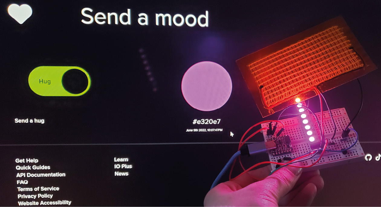
Figure 9.3 – The project we will be building
As shown in the preceding figure, the project will be first made on the breadboard. The photo shows me holding this breadboard up in front of my computer screen, where I have a web page open on my dashboard to alter the color of NeoPixels (and other exciting things too!).
Let’s head to the next section now, where we look at implementing our prototype piece by piece.
Building up your prototype – function by function
It’s finally time to get building. With our thoughts on planning done, there’s just a few reminders of some of the techniques we’ve been learning along the way.
Here are some top tips for a successful project:
- Try to build your projects in sections. This also gives you a sense of accomplishment when something works. I’ve had the experience of trying to do too much at once and then there seems to be an insurmountable number of errors to fix.
- Prototype small and in a non-permanent way. All I mean by this is when you start the circuit, try to use croc clips or breadboards, and hook up wires so that you can easily fix, move, repair, and try things out.
- Don’t forget to check your board and port every time you disconnect and connect the board to your computer and Arduino.
- It’s a good idea to prototype and test the connections as you finish them. This might be checking for continuity or where a wire might be bridging or overlapping another.
- Check the data sheets, grab the library, and try the sample code to see it all working.
- Never leave your board powered on when you are swapping components.
Start with the easiest part or the part of the circuit you’re most familiar with and have used before. It’s a great feeling to get something working and it’s motivating to help spur you on with the rest of your circuit design. Sometimes, a larger project can seem daunting or even insurmountable. All projects are possible if we take them in steps! I often work on a simpler version of a project and then as it’s realized, I add extra interactions or components to it if it’s needed (or just for fun).
Our project build – sending a mood
Can a heating pad be used as a communication device? What if when friends and family are thinking about us, they could send some warmth our way? That’s what we’re going to do in this system.
The wearable we are going to make is a prototype that will consist of an ESP32 board. It’s a small board that I mentioned briefly in Chapter 7, Moving Forward with Circuit Design Using ESP32, the Adafruit QT Py ESP32-S2. We will also be using a few outputs (Figure 9.4) for the prototype, including the following:
- NeoPixels as a visual output
- A heating pad (https://www.adafruit.com/product/1481) as another feeling or sensation output, a 1N4001 diode, a 270-Ohm resistor, and a PN2222 transistor to enable the heating pad
- A small vibration motor
We will be sensing the heat, the colors visually, and the vibrations as well. Our hyper-body system will play with several of the senses but not necessarily with the traditionally designated senses:
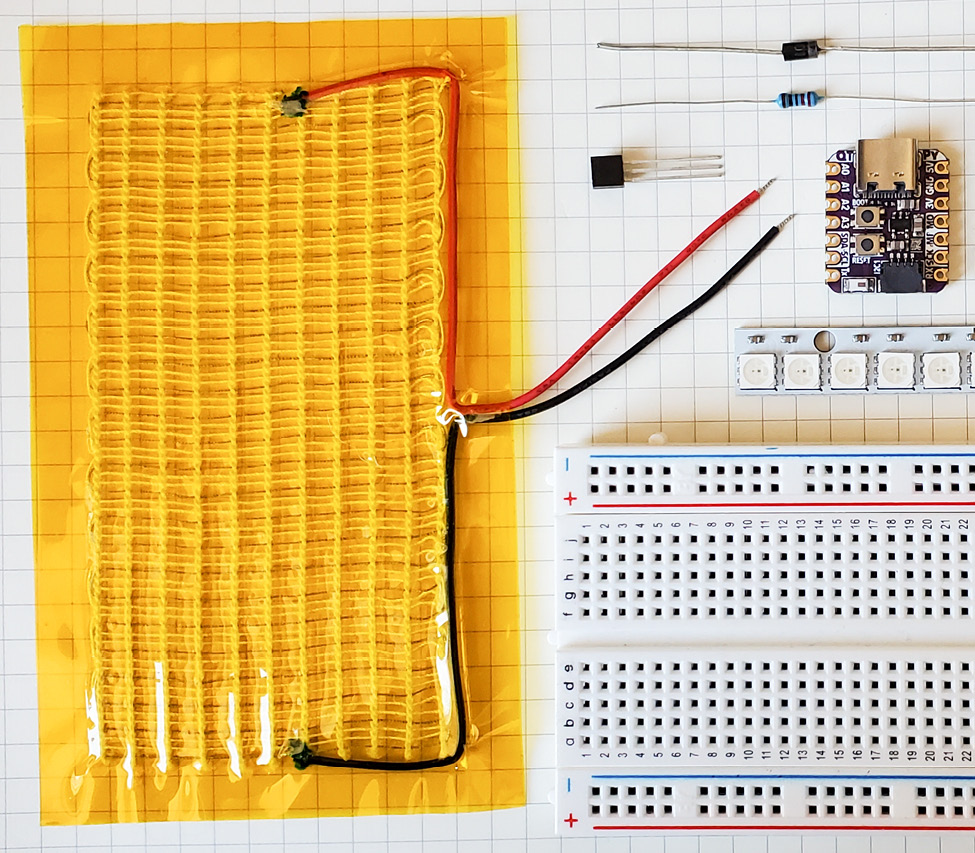
Figure 9.4 – The components for the circuit
The input will involve communication through the internet, straight to our QT Py ESP32-S2. Therefore, we will use the ESP32-based board because it has Wi-Fi capabilities. Our hyper-body wearable will use several of our senses within the wider definition, as we are using touch in terms of heating and the message it conveys. This is based on the importance of good mental health and well-being. Additionally, there will be vibration and visuals in terms of light.
About the QT Py ESP32-S2
Let’s learn a little bit about the QT Py ESP32-S2 before we dive in. This board is tiny! It measures 21.8 mm x 17.9 mm x 5.7 mm, which is great for a wearable when we don’t want any large circuit boards visible. It also has a STEMMA QT connector, which is a chainable I2C plug and play port so you can quickly and easily plug in many I2C devices to it – inputs and outputs. This is compatible with Seeed Grove I2C boards as well. It has a USB-C as a connector and uses an ESP32-S2 240 MHz Tensilica processor with a native USB – meaning it can operate as a keyboard or mouse, musical instrument digital interface (MIDI) device, and disk drive. The Tensilica processor has one core, not the two cores that we saw with the other ESP32 boards. When you see S2 in the ESP module name (many boards now use the S2), this is a mini-module that has reduced capabilities. However, this won’t affect us, as we haven’t needed to use the second core for any of our projects yet. There is also no Bluetooth on this board, but there is a lot of space for our files, with 4 MB of flash and 2 MB of PSRAM. There is also an RGB NeoPixel in place of the common pin 13 LED that we see on many boards.
Lastly, it has 13 GPIO pins, so we can use it for a lot of connections! For the full rundown on the features and specifications of this board, visit https://www.adafruit.com/product/5325. There are other versions of this board, so to see the latest releases and what features you find you need, it’s best to get up-to-date information from the website.
Now that we know a little more about the board, we should get busy. We’ll begin by making our first connection, NeoPixels to the QT Py ESP32-S2. Let’s do this now.
Activity 9.2 – Making a connection (NeoPixels to the QT Py)
For this activity, we will connect the first output component to our board, the NeoPixel. I’ve chosen it first because we’ve hooked it up before (Activity 6.1 - learning about NeoPixels - a hand HEX system, specifically the third part of that activity, in Chapter 6, Exploring Reactions Through Outputs), so we will already have the NeoPixel library installed. If you haven’t followed along with a NeoPixel example in the book yet, then please refer to the activity in Chapter 6 and head back here to continue. For this activity, you’ll need the following:
- NeoPixels (any size, for now). I’m using a row of 8 to test this prototype.
- The Adafruit QT Py ESP32-S2 (https://www.tinkertailor.tech/product-page/esp32-s2-qt-py-wifi-dev-board-w-stemma-qt).
- A breadboard and jumper wires.
Let’s do this activity in two main steps.
Step 1 – Connecting and preparing to use a new board
We haven’t used the QT Py yet, so we need to check the board is in the Arduino program’s Boards Manager section. Let’s look there now.
Open Arduino. Navigate to the Tools menu | Board | esp32 and look for Adafruit QT Py ESP32-S2. See Figure 9.5 for a reminder on where to find the boards:
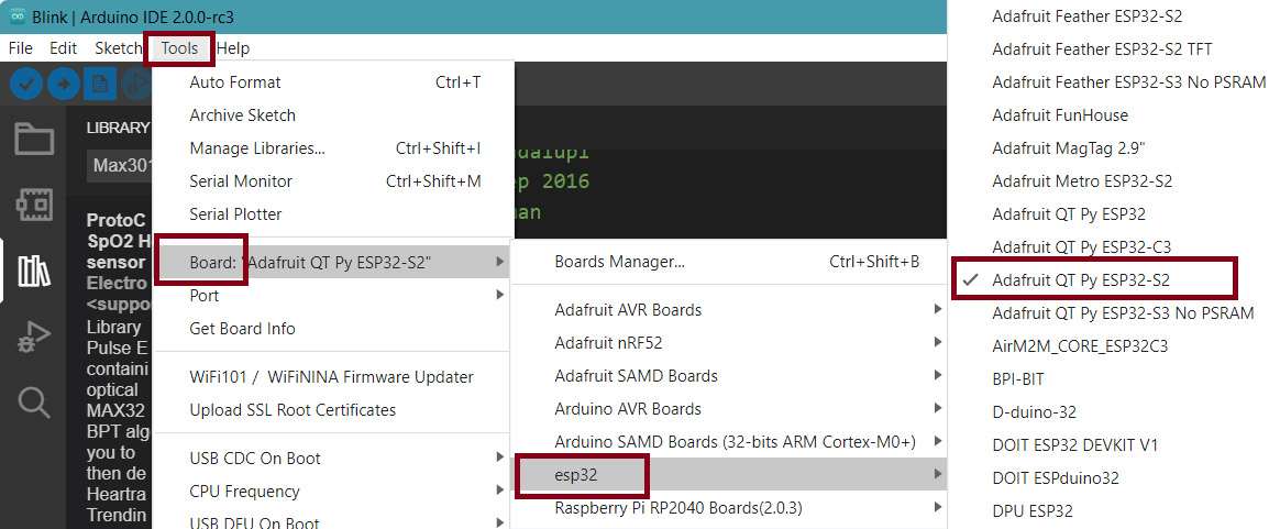
Figure 9.5 – Finding the QT Py board
If the board isn’t there, you’ll need to check in your Preferences that you have both board URLs in the boards manager section (see Figure 9.6 as a reminder). Pop open the bigger window (marked with an arrow) so you can see what URLs are already there – the little icon on the right-hand side of the text field.
For current URLs and information, always check https://github.com/espressif/arduino-esp32, the official site for the ESP32 boards:
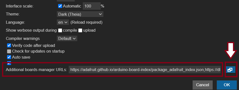
Figure 9.6 – Preferences and additional boards manager URLs
Then, in Figure 9.7, you can see the expanded manager with the URLs. For the Adafruit boards (https://adafruit.github.io/arduino-board-index/package_adafruit_index.json) and the ESP32 boards (https://dl.espressif.com/dl/package_esp32_index.json), if yours don’t look similar to mine, then copy in the URLs to match what I have and paste them in. Then, click OK. Click OK again to confirm in the Preferences window and you will be back to your main Arduino sketch window:
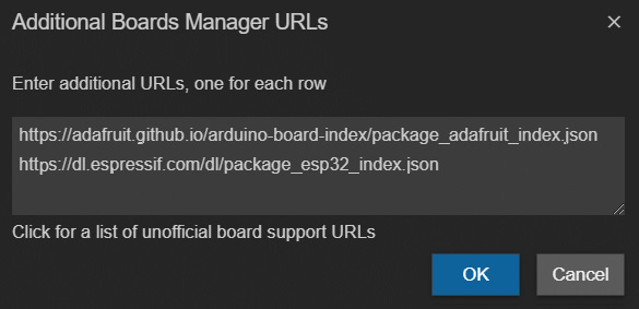
Figure 9.7 – The expanded boards manager URL window with the URLs shown
In the main Arduino window, click the Boards Manager icon in the left-hand side menu, the second icon down. Search for ESP32 (see Figure 9.8) and you’ll see our QT Py board is listed there. We installed these boards previously in Chapter 7, Moving Forward with Circuit Design Using ESP32. However, if you don’t have the QT Py listed in your set of boards (also see Figure 9.8), then I would click Install again and wait for it to install. Once it has finished, close Arduino and then open it again. Now, check again, as in Figure 9.5, to check the QT Py is listed for you in the esp32 menu:
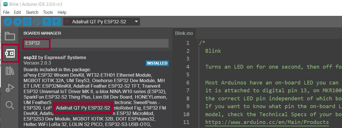
Figure 9.8 – Adding the ESP32 boards to Arduino
Now that the board is added, do you remember what our next step should be?
If you said "test the board and our connection to it," you’d be right! So, go ahead and plug your board into your computer and choose board and port in the Arduino Tools menu.
We usually check the board, port, and connection to our computer by uploading a sample blink sketch. However, the QT Py board doesn’t have an LED on pin 13 – it has a NeoPixel, which is an RGB LED on a different pin. This is good news for us because we will be adding NeoPixels to our QT Py after our board setup. This way, we will already know that we can successfully program a NeoPixel with the QT Py. Let’s test the board now. You’ll need the following code, which you can download here: https://github.com/cmoz/Ultimate/tree/main/C9/9.2_Blink. In the code, we start by including the NeoPixel library in our sketch, and then defining the number of pixels:
#include <Adafruit_NeoPixel.h>
#define NUMPIXELS        1
Adafruit_NeoPixel pixels(NUMPIXELS, PIN_NEOPIXEL, NEO_GRB + NEO_KHZ800);
void setup() {
  Serial.begin(115200);
#if defined(NEOPIXEL_POWER)
  pinMode(NEOPIXEL_POWER, OUTPUT);
  digitalWrite(NEOPIXEL_POWER, HIGH);
#endif
  pixels.begin();
  pixels.setBrightness(20);
}
void loop() {
  Serial.println("Hello!");
  pixels.fill(0x0225DD);
  pixels.show();
  delay(500);
  pixels.fill(0x000000);
  pixels.show();
  delay(500);
}
In the setup() section of code, we can see after initializing the Serial Monitor that there is an #if defined section. This code will only execute if the board has a power control pin. If it does, it will get set to HIGH, which enables the NeoPixel. If the code is written as an #if defined statement, it won’t execute if the board doesn’t have the power control pin, or whatever feature you’re writing your statement for. It’s a way of including code that won’t get executed and will produce errors – for example, if the board didn’t have a power pin.
After this, the NeoPixels are initialized, and we set the brightness to a low level. In the loop() function, we are printing to the Serial Monitor so we can do an extra check with our board, and then we are setting the pixel color to blue. The pixel lights up for half a second, and then goes off – a blink! Upload the code to your QT Py. You might need to press the reset button to see your changes after the code has been uploaded and have a look at the serial monitor to see the board saying “hello” to you too.
Quick challenge: Let’s be fancy and make use of the pixel – add red or another color to this blink so that it blinks two different (or three) colors. I’ve added this color to mine: 0xFF00FF. You’ll have to try it to see the color:
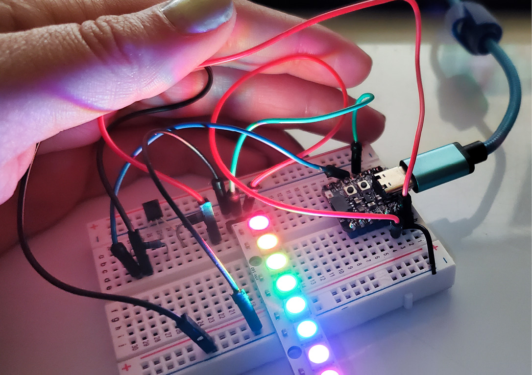
Figure 9.9 – Adding our NeoPixels to the QT Py ESP32-S2
Now that we have prepared Arduino to work with our board, we can proceed to the second step.
Step 2 – Hooking up the NeoPixels to the QT Py
Unplug your QT Py from your computer to connect the NeoPixel component. Then, hook up the ground and power lines of your NeoPixel to your QT Py, and the Data-In (DI) pin will hook up to pin A2 – note this is GPIO 8 for the code – so it looks as follows:
- GND on the NeoPixel > GND on the QT Py
- PWR on the NeoPixel > 3V on the QT Py
- DI on the NeoPixel > A2 on the QT Py
Plug your QT Py back into your computer. Let’s add code to see it working. Starting with the NeoPixel library, we will implement a rainbow effect along the strip or circle NeoPixel that you have chosen. We will declare the pin our pixels are on, A2, and I’ve also put the number 8 in the code line, Adafruit_NeoPixel strip = Adafruit_NeoPixel(8, neoLine, NEO_GRB + NEO_KHZ800);, because the strip I’m using has eight NeoPixels on it. Change this value to match what you have chosen. The completed code can be downloaded here: https://github.com/cmoz/Ultimate/tree/main/C9/9.2bNeoPx. In void loop(), we are calling one function, rainbowEffect(20); – this runs the code inside the rainbowEffect function:
void loop() {
  rainbowEffect(20);
}
The function, rainbowEffect(), cycles through color variations and five cycles of all the colors complete with for (y = 0; y < 256 * 5; y++). This is a color transition of red to green to blue and back to red again:
void rainbowEffect(uint8_t wait) {
  uint16_t x, y;
  strip.setBrightness(45);
  for (y = 0; y < 256 * 5; y++) {
    for (x = 0; x < strip.numPixels(); x++) {
      strip.setPixelColor(x, Wheel(((x * 256 / strip.numPixels()) + y) & 255));
    }
    strip.show();
    delay(wait);
  }
}
Upload the code to your QT Py. Once you see the success message after it is uploaded, press reset on the board, and you should have the NeoPixels in a rainbow color formation.
Now that we have our working NeoPixels with the QT Py board, we should hook up another component and repeat this process to increase the complexity of our wearable – with the heating pad!
Activity 9.3 – Adding the warmth of a heating pad
A heating pad can be used as a communication device. What if when friends and family were thinking about us they could send some warmth our way? That’s what we’re going to do for this wearable system. The heating pad component for Arduino typically comes in two sizes, and I’m using one that is 10 cm x 15 cm. We looked at the connection for this component when we used an axial fan in Chapter 6,Exploring Reactions Through Outputs, and there is a circuit diagram for it in Figure 6.32, Figure 6.33, and Figure 6.34. Please refer to those images for a reminder and a clear diagram. To make the circuit we need the heating pad, a 1N4001 diode, a 270 Ohm resistor, and a PN2222 transistor.
Using the breadboard from the NeoPixel connection earlier, add the diode, resistor, and transistor to start with. Double-check your connections and the orientation of your transistor and diode. As a reminder for the transistor, diode, and resistor setup, you can look to Figure 9.10 for three views moving closer to the circuit. Note that I’ve hooked the heating pad to 5V (via the diode silver side), not 3.3V:
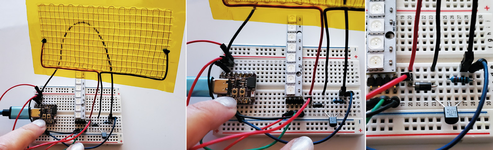
Figure 9.10 – Views of the circuit (use 5V on the QT Py)
The heating pad is connected to pin A3 on the QT Py, which is GPIO 8 in our code. If you are ever uncertain of what the pin numbers are, search for a pinout diagram for the circuit board you are using. I do this often because there are a lot of circuit boards with many variations. It’s the only way to be accurate with your pin names.
In Figure 9.11, we can see a figure from the PDF that has all the information about the board. The product PDF (https://cdn-learn.adafruit.com/downloads/pdf/adafruit-qt-py-esp32-s2.pdf) and similar ones are usually available for most circuit boards. It will list the pin outs for the microcontroller board and what they can be used for – for example, SPI and pulse width modulation (PWM). Look at pin A3/8 in the following diagram:
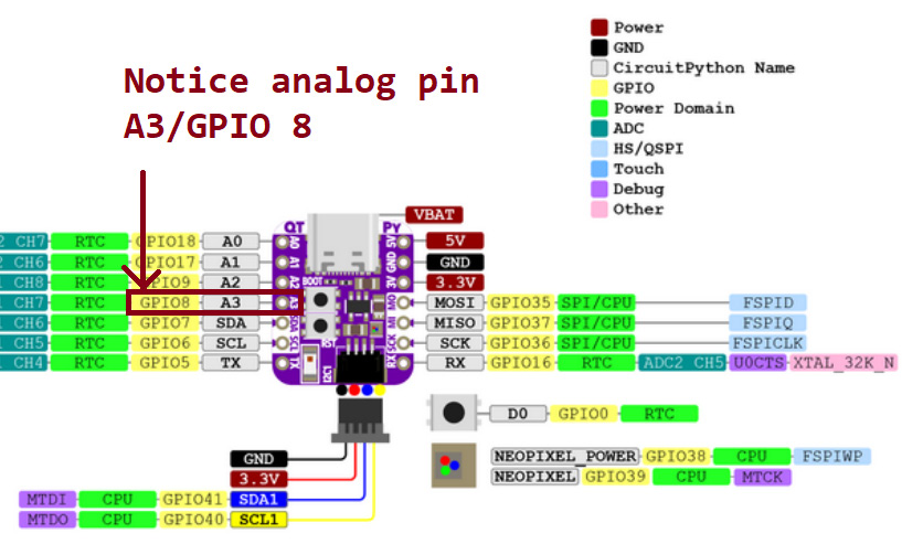
Figure 9.11 – An Adafruit pinout diagram for the QT Py ESP32-S2
I usually have the pin diagrams for my favorite boards printed out and nearby so I can quickly check which pins are SDA or SCL or the SPI pins of MISO, MOSI, SCL, or CLK. You might do the same when you’ve discovered which boards are your favorites.
After you’ve hooked the heating pad up, plug your board in and upload the code to test your connections – there is nothing in our loop() function for this code:
int heatPin = 8;
void setup() {
pinMode(heatPin, OUTPUT);
digitalWrite(heatPin, HIGH);
}
Once uploaded, the heating pad should slowly and gently be getting hotter – or warmer, rather. It won’t get very hot. We could add to the circuit and incorporate a second heating pad in the future. One last comment about the heating pad – you don’t need to be too gentle. I’ve seen people fold it in half for projects or curve it around a surface, for example. It isn’t as delicate as it looks, so you can be creative but mindful.
That’s another activity successfully completed. If your heating pad isn’t getting warm, check that the transistor is pointing in the correct direct, and triple-check your connections.
Connecting the QT Py to the internet
We’ve chosen to use the Adafruit QT Py ESP32-S2 board for a few reasons, such as its small form factor, the huge number of accessible pins, the ability to expand our circuits easily and quickly with STEMMA QT connections, but also because it is an internet-capable board. A STEMMA connection is a three- or four-pin JST PH connector that manufacturers have been putting on boards over the last few years to make connecting components quicker. The four-pin version is for I2C use.
We will create a way for our friends and families to send colorful feelings to us, or if we give the wearable to a loved one, for us to send colors to them. This will be done using an IoT service. To do this, we will have to follow a few steps to create and use an online service, https://io.adafruit.com/, to make a connection. There are other services available – however, this service has a lot of support and users, so it is a good place to start. Let’s go to Activity 9.4 and set up our account and connection now.
Activity 9.4 – Getting connected to an IoT service
Adding IoT capabilities to our wearable will allow others to interact with the system. I find this an exciting prospect! However, there are a few steps to follow to set this up initially. Once you have done this process once, it will get easier and you won’t have to do all the account setup again:
- If you don’t have an Adafruit account, we’ll set it up now. Head over to https://io.adafruit.com/ in your browser and click on Get Started for Free in the top-right-hand corner.
- Once you’re signed up and are logged into the site, look for your key in the IO navigation window (see Figure 9.12). You’ll notice the key symbol. Click this to open your key area. This is where you’ll access your username and active key that we need for a config.h file when we connect to Arduino:
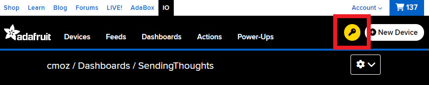
Figure 9.12 – Accessing your username and key for the io platform
- Copy your username and active key to Notepad or somewhere similar so you have them handy. Then, let’s paste them into the config.h file:
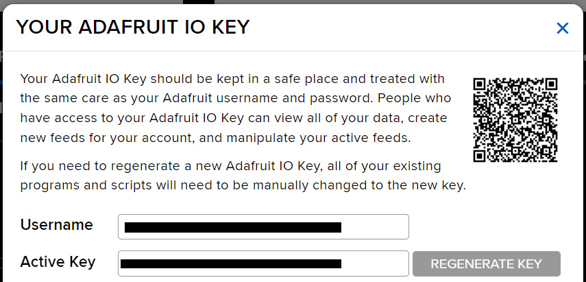
Figure 9.13 – The IO Key
- Let’s open Arduino and we will install the Adafruit IO Arduino library. Open the LIBRARY MANAGER and search for Adafruit IO. When you click Install all, there will be a message window that asks about installing dependencies (see Figure 9.14). These include important ones, which are the server files:
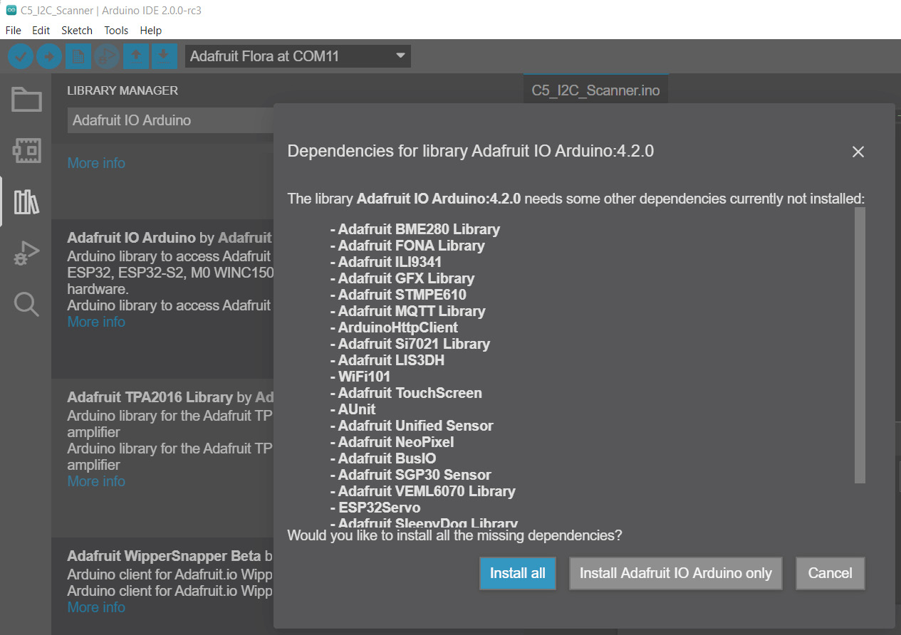
Figure 9.14 – The associated libraries with Adafruit IO
- Once the libraries have all been installed, you can open the sample file from File | Examples | Adafruit IO Arduino | adafruitio_14_neopixel in the Arduino IDE (see Figure 9.15). If you don’t see it, close Arduino and open it up again. If you still don’t see it, go back and try to install the library again. This should fix any issues if you didn’t see it. When you open this file, you might notice something a little different about it:
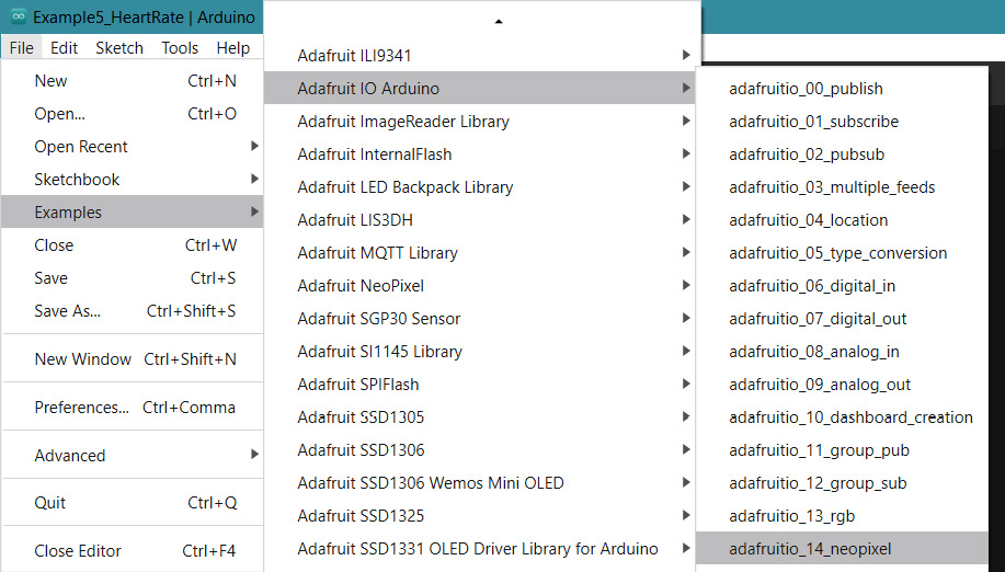
Figure 9.15 – Opening an example file in Arduino
- This file has two tabs (see Figure 9.16), one that is the file name, adafruitio_14_neopixel, and another that is a config.h file. This has opened as a tab because if you look at the adafruitio_14_neopixel.ino file, it includes the config file. We need the information in the config file to load for this sketch to work:
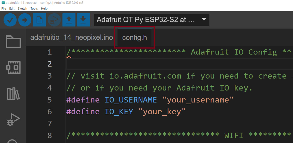
Figure 9.16 – Showing the tabs in this Arduino file
The config.h file is where all the connection information is – let’s edit it now.
- Click on the config.h tab and we will change a few values. Starting with the first values, we need to input IO_USERNAME and IO_KEY, which we got from our account at https://io.adafruit.com/ and which we copied earlier (see Figure 9.12 and Figure 9.13).
The code to alter is the following:
#define IO_USERNAME "your_username"
#define IO_KEY "your_key"
- Next, you’ll need to enter your current Wi-Fi details for the network that you want to connect to in the following code:
#define WIFI_SSID "your_ssid"
#define WIFI_PASS "your_pass"
Change your_ssid to the name of your Wi-Fi network and then also change your_pass to your Wi-Fi network password. Click Save for this file so you don’t lose your progress, and change it to mod_adafruitio_14_neopixel or something similar so you can find it again.
Now, we need to create the data service to connect to. Let’s return to io.adafruit.
- When you are back on io.adafruit, click on the Feeds tab (see Figure 9.17) so we can see our feeds. We don’t have any feeds yet, so we will create a new feed:
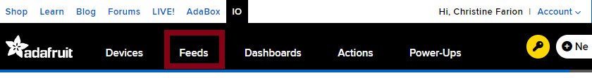
Figure 9.17 – Opening your Feeds view
To create a new feed, click on the + New Feed button (Figure 9.18). This will open a window with two fields – one for a feed name and one for the description. I’ve called mine send_a_thought and I didn’t enter a description, but this is a good idea, especially when you start to create many projects:
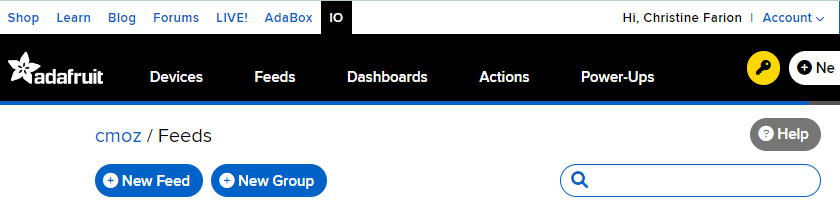
Figure 9.18 – Creating a new feed
Once the feed has been created, you will see it in your feed list along with the Welcome Feed that is there by default when you set up your account. The next thing we need to do is add a new Dashboard.
What is a feed?
A feed contains the data values that get pushed to your device. It also contains the metadata information about the data you use for your IoT connections. This includes information on whether your data is private or public, the general description of the data, if you’ve written one, the date and time, and if there are any license settings for it. One feed needs to be created for each form of data you want to send. For example, if you want to use a toggle to control something, that takes one feed, and if you want to add data from a distance sensor, that will need a feed too.
When you plan your wearable, be aware of how many data feeds you might need in your project and how often you call (or access) them. The free plan has limitations – at the time of writing, it was 10 feeds with 30 data points per minute. You can create five dashboards on the free plan too. Now, let’s create a dashboard.
- In the navigation bar, click on the Dashboards tab to open your Dashboards. This will open your Dashboards area:
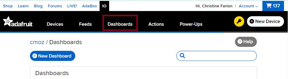
Figure 9.19 – Creating a new Dashboard
- Once there, click the + New Dashboard button (see Figure 9.19). This will open a new window for you to create your dashboard. Type the name of your dashboard and a description.
- The Dashboard will be the interface part of your IoT connection. It allows you to visualize the data generated and received. I’ve called mine SendingThoughts so that I’ll recognize my project. After you have created your dashboard, it will show you all your dashboards. Click on the one that you just made:
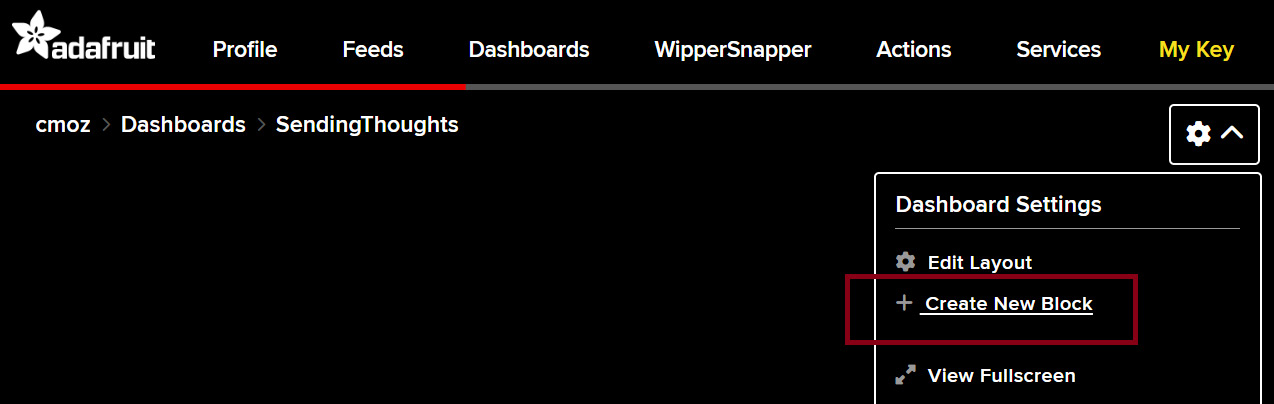
Figure 9.20 – The Dashboard for our project
This will open that dashboard (see Figure 9.20) and now we can create the application visuals and controls that we want people to interact with.
- Navigate to the settings-style icon on the right-hand side of this screen and click the drop-down arrow. You will now have several options available to you. We want to choose + Create New Block:
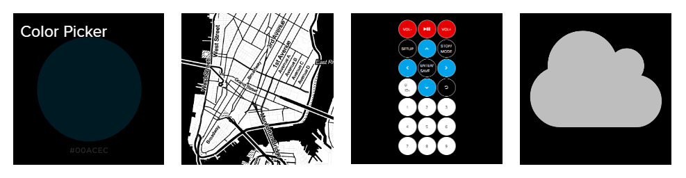
Figure 9.21 – Choosing our IoT elements on our dashboard (Color Picker)
- Creating a new block opens a new menu. This has all the elements available to us for our IoT wearable. I’m choosing Color Picker, which is shown in Figure 9.21. When you select this item, a new window opens, Connect a Feed, shown in Figure 9.22:
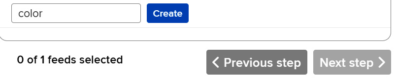
Figure 9.22 – Connecting the dashboard elements to a feed
Create a new feed name called color, click Create to make it, and then click Next step:
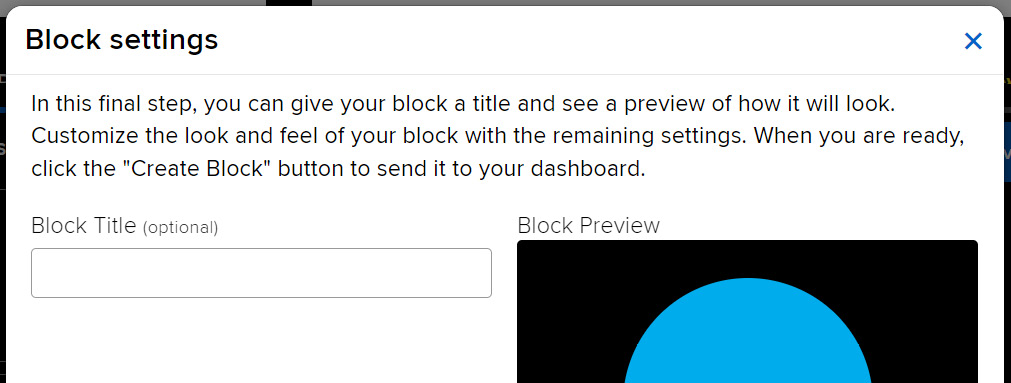
Figure 9.23 – Block settings
- The Next Step button launches the settings and customization for the element we’ve chosen. When you have a chance, I would recommend coming back to the settings and customization window and trying each connecting element, looking at the settings, and getting a feel for what might be possible to create.
There isn’t much to change with this Color Picker component. You can also change the settings for the components you made at any time.
Your dashboard with your component is now visible; I’m going to add text as a title for the dashboard that will be seen when someone goes to it online, "Send a color", so people know what to do when they get here. The last step here is to change the privacy setting of this dashboard. Let’s finish this in our last step:
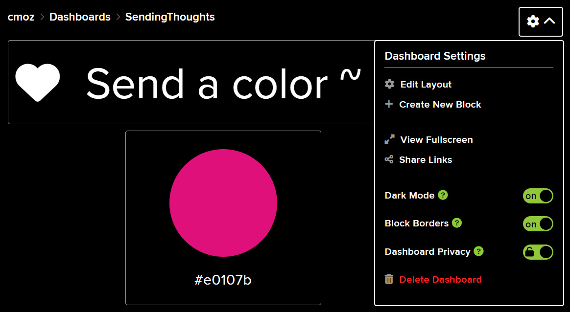
Figure 9.24 – The Dashboard Privacy setting tab in Dashboard Settings
- Click the settings icon and navigate down to the Dashboard Privacy tab (see Figure 9.24). Click it to slide it and a Warning popup will appear (see Figure 9.25). This is to confirm that you want to make this dashboard public. We do want it to be public – otherwise, no one would be able to use it, and that’s not very interactive:
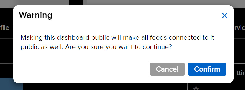
Figure 9.25 – The privacy warning
Click Confirm to the warning message. You can turn off the privacy again if you want to make changes.
You’ve done it – you’ve made your IoT dashboard and interactive area for people to visit. Now, we need to program our Adafruit QT Py ESP32-S2 board, so let’s head back to Arduino, open it, and I’ll see you there!
Activity 9.5 – Coding our ESP32 to access the IoT connection
Earlier, we opened an example file and entered our credentials. Go to that file again now – we saved it as mod_adafruitio_14_neopixel. There are only a few things we need to change. First, define your PIXEL_PIN variable as A2, which is what we used in our circuit. Change PIXEL_COUNT to the number of pixels you are using. Those lines of your code should look as follows:
#define PIXEL_PIN A2
#define PIXEL_COUNT 8
Further down in the setup() function, in the very last few lines, between pixel.begin(); and pixels.show();, I added a line of code for the brightness. I found that without it, the pixels were too bright. So, my code looks as follows just before the closing curly brackets of the setup() function:
pixels.begin();
pixels.setBrightness(64);
pixels.show();
If your config.h file has been altered with your credentials and Wi-Fi information, you should upload the code to your board. After it is uploaded, open the serial monitor. Press reset on your board, and you should see connection information in the monitor – connection to the Wi-Fi and the Adafruit IO service. Mine is shown in Figure 9.26 as it’s finding and checking credentials:
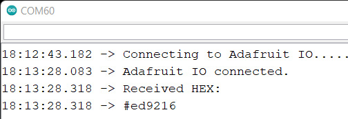
Figure 9.26 – Checking the output after upload and pressing reset
Now, for the fun part – go back to the Adafruit dashboard that you made earlier. Click on the color picker and you can choose another color. Your NeoPixels will have changed color according to the color you chose:
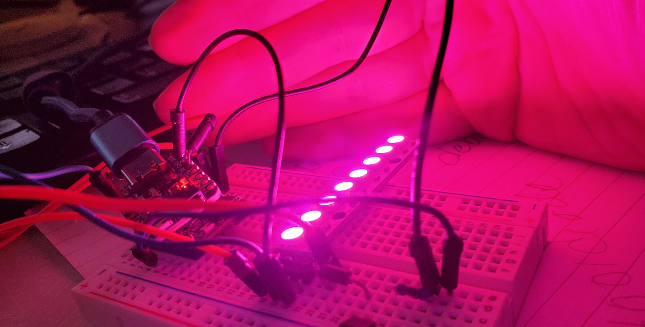
Figure 9.27 – A bold pink color to test my connection
Now that we’ve connected and tested this by looking at the colors of our NeoPixels, we should take a closer look at what the code is doing. This will help us to write code to add other objects and make changes.
What’s the code doing?
If we have a look through the code, the feed we set up is configured in the code:
AdafruitIO_Feed *color = io.feed("color");If we created a feed called temp, to take a temperature reading, we would write AdafruitIO_Feed *temp = io.feed("temp");, for example. We also have to make a connection to connect to the IO service and there is a function, io.connect();, that does this for us. Our program then accepts any messages that it might be receiving from the IO platform. This is the message handler. In this example, this color->onMessage(handleMessage); function is called when there is a message received. Next, in the code, we wait for the connection to be initiated. We can see in the serial monitor that a . symbol is generated for every half-second that we wait:
  while(io.status() < AIO_CONNECTED) {
    Serial.print(".");
    delay(500);
  }
While still in setup(), we call the color->get(); instance method that checks whether there is a feed – true if successful or it will return false. In loop(), we maintain the connection to IO with io.run(); and will process the data. It needs to be called often to keep the connection to the service.
The handleMessage() function that we called earlier pulls in the data from the calling feed – in our example, this is from color->onMessage(handleMessage), and every time a message from the color feed is received, this function is executed. It will use the color information received and set the color of our NeoPixels with it:
void handleMessage(AdafruitIO_Data *data) {
  Serial.println("Received HEX: ");
  Serial.println(data->value());
  long color = data->toNeoPixel();
  for(int i=0; i<PIXEL_COUNT; ++i) {
    pixels.setPixelColor(i, color);
  }
  pixels.show();
}
For all the information on the classes and methods that we can use with the Adafruit IO library, you can visit https://adafruit.github.io/Adafruit_IO_Arduino/html/index.html.
Now that we’ve got the NeoPixel and QT Py ESP32-S2 connected to an IoT service, and we have a heating pad that we know works, let’s put them together in one sketch before we take a break!
Activity 9.6 – Putting it all together
We’ve followed good practice and managed to get the parts working. This is great because it means we know where any errors were and we were able to fix them as we went along. All that remains, for now, is to add some interaction with our heating pad.
I returned to Adafruit IO to create a slide-toggle switch:
- I went back to my dashboard
- I selected + Create New Block
- I chose Toggle
- I connected it to a new feed, which I called button
- The entries were 0 for Button On Value and 1 for Button Off Value (see Figure 9.28):
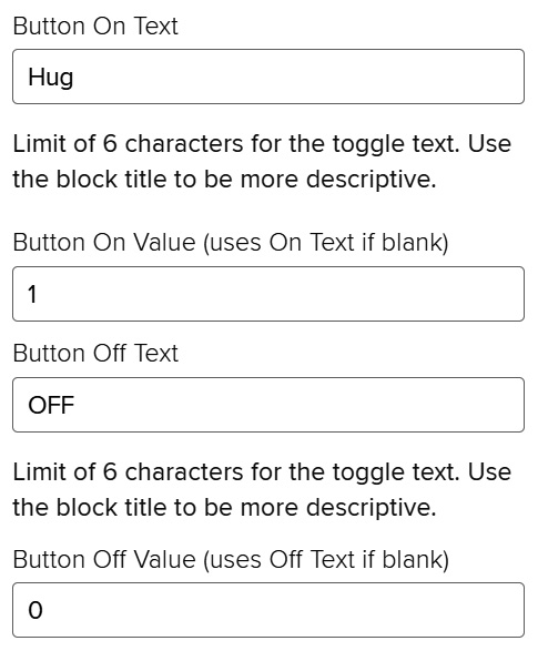
Figure 9.28 – Adding a toggle to the dashboard
Click Save for your layout once you’ve added the button, and then we need to connect to it to get it to interact with our QT Py ESP32-S2 board. To see how I’ve altered my dashboard, Figure 9.29 shows the added text and toggle:
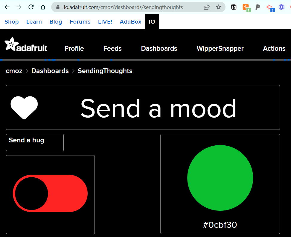
Figure 9.29 – My toggle added to the dashboard
We will amend our code to add in the toggle, which will be the remote input to activate our heating pad. Make sure your circuit is all connected (the NeoPixels and heating pad to the QT Py) and the complete code can be downloaded from https://github.com/cmoz/Ultimate/tree/main/C9/9.3HeatNeoIo.
If you remember from earlier, we need to set up the feed, so if you look in the completed code, we added this line, AdafruitIO_Feed *button = io.feed("button");, just after our color feed setup code line. In the setup() function, we also add the message handler for this toggle – for the color feed, we had color->onMessage(handleMessage), so? what could we write to add a message handler for our new feed?
button->onMessage(handleHeatMessage);
I wrote a function called handleHeatMessage, so I know which data it is handling. Inside this function is the following code:
void handleHeatMessage(AdafruitIO_Data *data) {
  Serial.print("received <- ");
  if(data->toPinLevel() == HIGH)
    Serial.println("Heat On");
  else
    Serial.println("Heat Off");
  digitalWrite(heatPin, data->toPinLevel());
}
This will control the pin that our heating pad is connected to and turn it on or off with the toggle.
Lastly, I added a small vibration motor to pin A1 and set it to vibrate when it receives a new color change. For this, I added a few lines of code that you can see in the completed version you have, but it includes the following in the handleMessage() function:
  digitalWrite(vibrationPin, HIGH);
  delay(500);
  digitalWrite(vibrationPin, LOW);
Also, the pin number is declared and in setup(), we define it as an output.
Hopefully, you’ve got this all connected and working. Remember, once you’ve uploaded the code, you need to open the serial monitor to see it connecting and accessing the IO service. Typically, you’ll see an output similar to Figure 9.30:
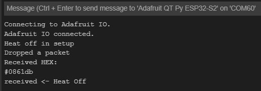
Figure 9.30 – The output in the serial monitor connecting to the IO service
I hope you enjoyed working with this little board and internet service. There were many steps to follow and it will take a few tries at implementing feeds and making dashboards to really understand it all. When you have time, head back to IO and look through some of the possibilities for creating more IoT wearables.
At the moment, we’ve created a prototype on a breadboard, and you may be wondering how will we be wearing this. Well, in the next chapter, Chapter 10, Soldering and Sewing to Complete Your Project, we will be learning to sew, solder, and complete this working prototype. We’ll be making it a wearable one. So, there is a lot of fun coming up!
Troubleshooting
If you have any issues while connecting, then you might start by checking that you have altered the information correctly in the config.h file. Make sure you’ve got the username and the key copied exactly. Also, make sure you’ve got the correct Wi-Fi credentials.
To verify that you don’t have internet issues, you can alter the Serial.println(.); code to Serial.println(io.statusText()); – this will print to the serial monitor what the possible errors are:
// wait for a connection
while(io.status() < AIO_CONNECTED) {
Serial.println(io.statusText());
delay(500);
}
Check for a network disconnect message, which indicates that there is an issue with the internet connection. For other messages, try searching for them and going to the forums for IO.
I also had difficulties with my board dropping out or not being found on the port and other similar issues. I found I had to close Arduino and then relaunch it. Version 2.0 of the IDE is new and there are still glitches, so if you are finding it’s being a little buggy, then closing and reopening should help with many errors. I’ve mentioned before that I’ve also had to reinstall libraries sometimes.
Don’t forget there is a wealth of good information on the Arduino forums if you get stuck.
Summary
This has been another exciting chapter with a big learning curve – but so rewarding! I hope you find time to go back over some of the concepts and techniques and run through the project again, adding other data feeds or making a new dashboard. We looked at what a hyper-body system is and what the senses we can try to incorporate are. We looked at how to design, choose materials and components, and the importance of placement and planning. We then discussed building our projects up function by function – which we then put into practice. We started by adding the Adafruit QT Py ESP32-S2 board to Arduino, we added NeoPixels, then a heating pad, and then connected to an IoT service! It really was a busy chapter.
We’ve got the makings of an exciting wearable, and we will take our breadboarded work and turn it into a wearable garment in the next chapter as we learn techniques for how to sew and solder. This will bring our project to an exciting close and you will be equipped to make wearables, from the early stages of the prototyping process, through to creating high-fidelity prototypes. I’m excited to put it all together.
References
Some of the information in this chapter mentioned projects or research from the following papers:
Singhal, S., Neustaedter, C., Ooi, Y. L., Antle, A. N., & Matkin, B. (2017, February). Flex-n-feel: The design and evaluation of emotive gloves for couples to support touch over distance. In the proceedings of the 2017 ACM Conference on Computer Supported Cooperative Work and Social Computing (pp. 98-110). https://www.researchgate.net/publication/313736576_Flex-N-Feel_The_Design_and_Evaluation_of_Emotive_Gloves_for_Couples_to_Support_Touch_Over_Distance.
Gooch, D., & Watts, L. (2012). It’s neat to feel the heat: how can we hold hands at a distance?. In CHI’12 Extended Abstracts on Human Factors in Computing Systems (pp. 1535-1540).
Mueller, F. F., Vetere, F., Gibbs, M. R., Kjeldskov, J., Pedell, S., & Howard, S. (2005, April). Hug over a distance. In CHI’05 extended abstracts on Human factors in computing systems (pp. 1673-1676).
Wilde, D., & Marti, P. (2018, June). Exploring aesthetic enhancement of wearable technologies for deaf women. In the proceedings of the 2018 designing interactive systems conference (pp. 201-213). https://www.researchgate.net/publication/324361454_Exploring_Aesthetic_Enhancement_of_Wearable_Technologies_for_Deaf_Women.
Hurban, H. Exploring the Intersections of Cultural Performance Practices and Wearable Technology. https://www.researchgate.net/publication/357811279_Exploring_the_Intersections_of_Cultural_Performance_Practices_and_Wearable_Technology.
Review questions
- What are some of the alternative senses that are discussed?
- What are some of the advantages of using clothing that already exists (how can we add wearables?)
- Can you describe the importance of planning ideas and thoughts?
- What are the two things we always need to check when we plug in our board and open Arduino?
- What is the limit of the ESP32 S2 chip?
- Why would we connect to a service such as io.adafruit?
- What is a feed for?
- Why do we have a Dashboard in io.Adafruit?