
11
Advanced Roadway Modeling Tool Belt for Everyday Use
In the previous two chapters, we had an opportunity to unwrap all of the land development and roadway modeling-focused tools available to us within Civil 3D, while also learning some very practical applications of how we can utilize them to further progress our residential subdivision design. Not only did we learn how to use these particular tools to create design objects within Civil 3D, but we also began to understand how best to manage these objects and the significance of each one to the overall design.
In this chapter, we’ll start off by refining our proposed surface models a little more through corridor manipulation efforts to ensure that our residential subdivision will drain during rain events. Refinement of our proposed surface models will be necessary before we consider putting on our Utility Modeling Tool Belt for Everyday Use in Chapter 12 and jump into the world of utility infrastructure that ultimately services our communities and land.
That said, in this chapter, we’ll be covering the following topics:
- Updating assemblies and designing driveways
- Designing a dead end
- Designing our residential subdivision main entrance
With that, let’s go ahead and open up our Grading Model.dwg file located within the Practical Autodesk Civil 3D 2023Chapter 11Model directory. Once opened, you’ll notice that we’ll be starting this chapter pretty much where we left off in the previous chapter, with the display of our model looking similar to that shown in Figure 11.1:
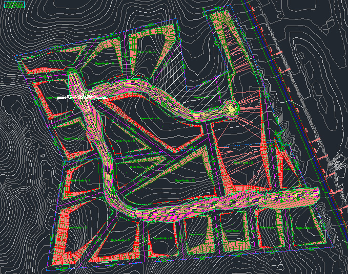
Figure 11.1 – Final appearance of our residential subdivision after Chapter 10
Technical requirements
The exercise files for this chapter are available at https://packt.link/UoiPn
Updating assemblies and designing driveways
With our Grading Model.dwg file open, you’ll notice that there are a few items that need to be cleaned up and accounted for right off the bat:
- Side slopes in cut and fill locations have not been consistently applied throughout our site
- Driveways, or lot access, will need to be designed so that we can properly locate our drainage structure and driveway culvert locations throughout our site
- SRF - Proposed Grade – Building Pads and SRF - Proposed Grade – Corridors Surface models are overlapping, resulting in conflicting proposed elevations on our site
Note
This conflict has the potential to resolve itself after the first two updates are accounted for.
Tackling these updates in sequence, we’ll start by zooming and panning over to all of our assemblies that were used to create all of our Corridor and Intersection models in Chapter 10, Roadway Modeling Tool Belt for Everyday Use. Once there, let’s use the following steps to update the subassemblies used in our assemblies (also shown in Figure 11.2):
- Go ahead and simply select all of the BasicSideSlopeCutDitch subassemblies on both the left and right sides of all of the assemblies.
- Open up our Properties dialog box.
- Update the slopes listed in our Cut Slope, Fill Slope, and Foreslope Slope fields to apply a 2:1 slope.
- Update the slope listed in our Backslope Slope field to apply a 2:1 slope:
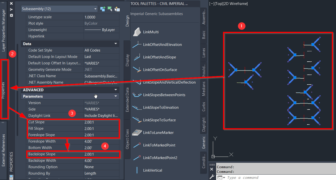
Figure 11.2 – Steps to update subassembly properties
- From there, let’s hop back over to our Toolspace | Prospector tab and scroll down to our Corridors and Intersections section. To update the corridors, we can simply right-click on the Corridor category and select the Rebuild All option. For our intersections, we’ll need to expand the Intersections category, right-click on the INT – Subdivision Side Road – Cul-De-Sac intersection, and select the Update Regions and Rebuild Corridor option.
Lastly, we’ll need to scroll up to and expand our Surfaces category, along with the Proposed Conditions subfolder, right-click on our SRF - Proposed Grade – Corridors Surface model, and select the Rebuild option. Once surfaces have been rebuilt, our roadway design should now be updated to accommodate the new slopes applied, with the next appearance of our site looking similar to that shown in Figure 11.3:
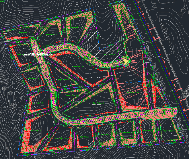
Figure 11.3 – Final appearance of our residential subdivision subassembly updates is applied
Although we still have a slight overlap of our proposed Surface models in the southeast corner of our site, we’ll go ahead and add the driveway locations next and come back to this location when we perform a final cleanup of our Surface models.
With that, let’s start adding our driveway locations to our residential subdivision layout. For this portion of edits, we’ll start by adding our driveway locations into our Grading Model.dwg file, and then copy this geometry over to our Site Plan Reference.dwg file thereafter.
Note
We’re starting in our Grading Model.dwg file to make sure that we have a good sense as to where we want to place our driveways based on the SRF - Proposed Grade – Building Pads Surface model. Our driveway linework will be essentially represented by polyline geometry, so we won’t be able to data reference these objects from our Grading Model.dwg file, hence the reason for us needing to copy into our Site Plan Reference.dwg file so that this linework ends up on our final sheets.
If we were to measure the distance from our edge of pavement line, where our roadway meets the curb and gutter, all the way to our setback line, we’ll measure out a distance of 28 ft. With our typical driveways being 12 ft wide, let’s go ahead and create a polyline using basic AutoCAD workflows—that is, 12 ft wide by 28 ft long.
Once created, let’s go ahead and place it on any one of our lots by using AutoCAD’s move, copy, snap, and rotation commands to properly place it on all of our lots with a perpendicular alignment to our roadway geometry, with the next stage looking similar to that shown in Figure 11.4:
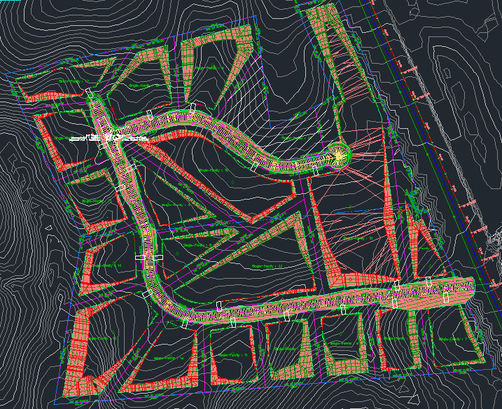
Figure 11.4 – Driveway locations added to the model
Once all driveway locations have been added, let’s go ahead and select all polylines representing the outlines of the driveways and use AutoCAD commands to copy and paste over into our Site Plan Reference.dwg file located in the Practical Autodesk Civil 3D 2023Chapter 11Reference directory. After all polylines have been copied over, we’ll go ahead and place them on the C-ROAD-FEAT layer, save, and close out of our Site Plan Reference.dwg file.
Now, back in our Grading Model.dwg file, we’ll jump back over to our assemblies and make a couple more modifications that will be applied to all. Ultimately, all we are going to do at this stage is add some ConditionalHorizontalTargeting subassemblies in between our BasicLane and BasicCurbAndGutter subassemblies.
By adding the ConditionalHorizontalTargeting subassemblies, we are adding instances where our Civil 3D Corridor and Intersection models will have to make a decision. In the event that driveway polylines are being detected perpendicular to the baseline alignments, we want our corridor to model out a portion of the anticipated driveway into each parcel. In the event that there is no driveway polyline detected, our corridor will continue the design as is.
With that, let’s activate our Subassembly Tool Palette again and use the following steps to update our assemblies:
- Activate the Conditional tab in our Subassembly Tool Palette.
- Select the ConditionalHorizontalTarget subassembly.
- Fill out the parameters in the Properties dialog box, as follows:
- Side: Left
- Layout Width: 12.00'
- Layout Grade: 1.00:1
- Type: Target Not Found
- Maximum Distance: 9999.00'
- Select the left side of the BasicLane subassembly.
- With our ConditionalHorizontalTarget subassembly still activated, go back to the Parameters section in the Properties dialog box.
- Switch the Type value from Target Not Found to Found.
- Select the left side of the BasicLane subassembly.
- Cancel out of the insertion process by hitting the Esc key on your keyboard, with the resulting assembly appearing similar to that displayed in Figure 11.5:
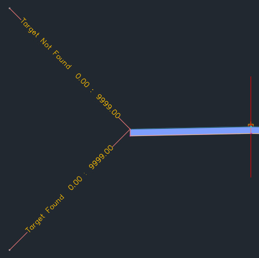
Figure 11.5 – Assembly with ConditionalHorizontalTargets added
- Select the BasicCurbAndGutter and BasicSideSlopeCutDitch subassemblies on the left side of the assembly to activate the subassemblies’ contextual ribbon.
- Select the Move tool in the Modify Subassembly panel.
- Move the BasicCurbAndGutter and BasicSideSlopeCutDitch subassemblies to the ConditionalHorizontalTarget subassembly with Target Not Found defined as the Type value.
With our Target Not Found type all configured, let’s jump down to focus on our Found type to place our Driveway and Daylight subassemblies on our SRF - Proposed Grade – Building Pads Surface model. We’ll use the following steps to accomplish this:
- Select our BasicLane subassembly to activate our subassembly contextual ribbon.
- Using the Copy command in the Modify Subassembly panel, we’ll copy the BasicLane subassembly to the found ConditionalHorizontalTarget subassembly on the same side of our assembly.
- Hit the Esc key to deselect all objects.
- Select the newly copied BasicLane subassembly at the end of the found ConditionalHorizontalTarget subassembly and go over to our Properties dialog box.
- Going down to the Parameters section, we’ll change the following values:
- Width: 28.00'
- Slope: 0.05%
- Hit the Esc key to deselect all objects.
- Select the BasicSideSlopeCutDitch subassembly on the same side of the assembly that we’ve been working on located at the end of the not found ConditionalHorizontalTarget subassembly to activate the subassembly contextual ribbon again.
- Using the Copy command in the Modify Subassembly panel, we’ll copy the BasicSideSlopeCutDitch subassembly to the end of the newly copied BasicLane subassembly, with the final output looking similar to that shown in Figure 11.6:
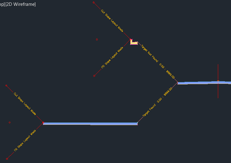
Figure 11.6 – Updated subassembly
Now that we’ve updated the left side of one of our assemblies, we’ll need to apply this configuration to the remainder of our subassemblies. You can either run through the same steps as outlined earlier to modify the remaining assemblies, switching from the Left to the Right side in the Parameters section in the Properties dialog box as required.
Or, you can simply use the subassembly contextual ribbon to mirror, copy, and move this configuration to all remaining assemblies, similar to the steps outlined in Chapter 10, Roadway Modeling Tool Belt for Everyday Use. Either way, the final assembly configurations should look similar to that shown in Figure 11.7:
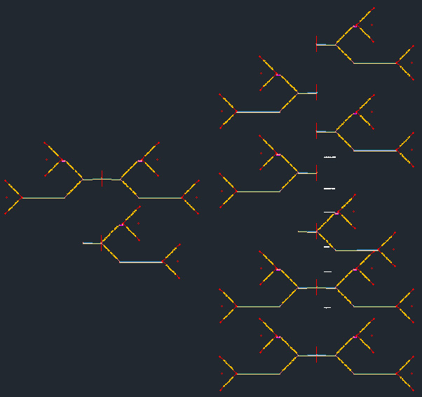
Figure 11.7 – Updated subassemblies
With all of our assemblies updated now, the next step we’ll want to take is to update our corridors and intersections. If we go back to our Toolspace | Prospector, let’s scroll down to our Corridor objects and expand the category. Starting with our COR - Subdivision Main Road - Access Corridor model, let’s go ahead and right-click on it and select the Properties option. When our Corridor Properties dialog box appears, we’ll want to switch over to the Parameters tab so that we can specify the new Driveway objects and our SRF - Proposed Grade – Building Pads Surface model to target all driveway locations.
In our Parameters tab, let’s go ahead and select the ellipsis symbol at the top of the Target column so that we can apply similar targets across the entire length of our COR - Subdivision Main Road - Access Corridor model—refer to Figure 11.8:
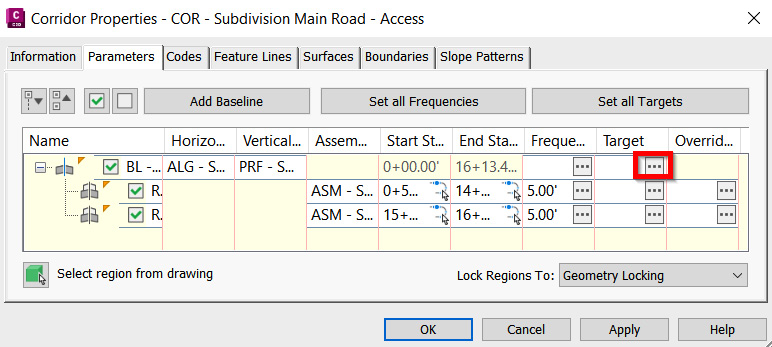
Figure 11.8 – Applying targets to all regions within a corridor
Once selected, a Target Mapping dialog box will then appear, allowing us to apply Offset, Elevation, and Surface targets to all subassemblies that have the option to target Feature Lines, Polylines, Survey Figures, Alignments, Pipes, Profiles, and Surface objects within our file(s).
In the Offset and Elevation tab, we’ll want to use the following steps to apply horizontal targets so that our corridor models will be able to intelligently make a decision within our file on how we should be grading our site based on the parameters we are feeding into it (also shown in Figure 11.9):
- Select the Offset and Elevation tab.
- Select all target offsets listed out.
- Click Select from the drawing option and select all polylines representing the driveways from the Site Plan Reference.dwg file along the corresponding Corridor model.
- Check the Use targets on the same side as the subassembly box:
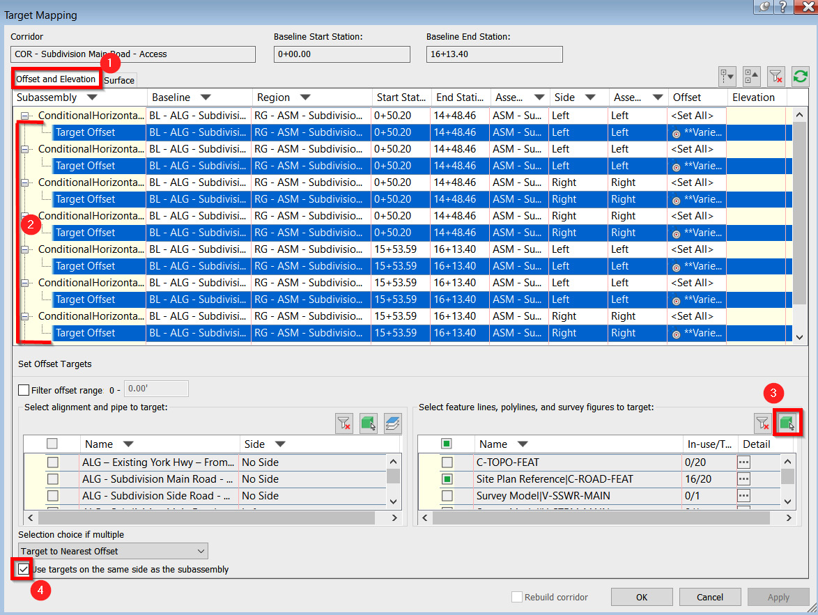
Figure 11.9 – Applying offset and elevation targets to all regions within a corridor
Continuing on, we’ll use the following steps to finish up our targeting (also shown in Figure 11.10):
- Select the Surface tab.
- Select all target surfaces and select the corresponding surface to target inbound Found and Not Found situations.
- Select the OK button:
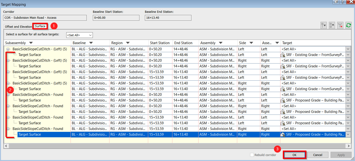
Figure 11.10 – Applying surface targets to all regions within a corridor
After selecting the OK button in both the Target Mapping and Corridor Properties dialog box, you will be asked if you’d like to rebuild your Corridor model, at which point we’ll want to select the option that does, in fact, rebuild our Corridor model. After Civil 3D rebuilds, you’ll notice that our Corridor model now accounts for driveway locations along the entire length of the baseline alignment.
For all other Corridor and Intersection models in our file, we’ll run through the same steps we just outlined to apply horizontal and vertical targeting to our ConditionalHorizontalTargets and Daylight subassemblies used to rebuild all remaining Corridor models.
Corridors have incredible flexibility and intelligence that, when applied the proper way, can make the design seamless. In this section, we learned some vital terms for understanding how corridors work, and in the next section, we will look at another portion of corridors—designing common conditions seen in roadways such as a dead end.
Designing a dead end
For our dead-end design at the end of our COR - Subdivision Main Road – Access Corridor model, we need to take a slightly different approach. Since a dead-end design is essentially the end of the road, and since we have applied a curb and gutter throughout the entire residential subdivision design, we’ll want to make a new assembly that includes just the curb and gutter along with the ConditionalHorizontalTargeting and Daylight options we included in the preceding section.
Before doing so, though, we’ll need to create a new feature line that will contain both Horizontal and Vertical values for our new dead-end Corridor model to use as a baseline. With that, let’s move to our Feature Line tools, which are located in the Create Design panel within the Home ribbon. If we select the down arrow next to Feature Lines, we’ll then want to select the Create Feature Line tool (refer to Figure 11.11):
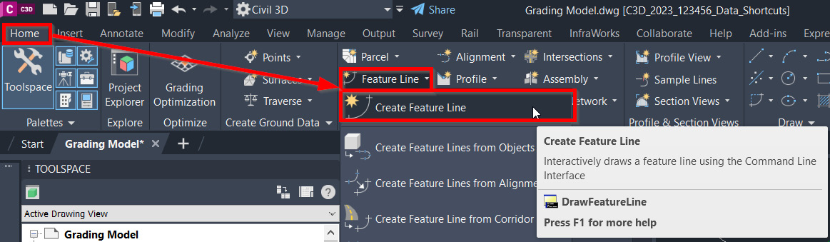
Figure 11.11 – Creating a feature line for a dead-end design
Once selected, we’ll be prompted with a Create Feature Lines dialog box, at which point we’ll want to create a new site, fill out the dialog box as follows (also shown in Figure 11.12), and then click on the OK button at the bottom of the dialog box:
- Site: SIT – Proposed – Dead End
- Style: Corridor Edge of Paved Shoulder
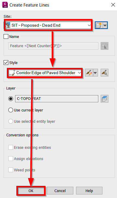
Figure 11.12 – Create Feature Lines dialog box
After selecting the OK button, we’ll be prompted at the command line to specify a start point. Starting with the northeast portion of our dead end, we’ll snap to the endpoint where our daylight line is.
Once clicked, we’ll then be prompted to specify elevation or [Surface], at which point we’ll type S for surface and select our SRF – Proposed Grade – Corridors Surface model, and click OK. This way, every point we click along the edge of our COR - Subdivision Main Road – Access Corridor model will be reflective of the elevations generated from our SRF – Proposed Grade – Corridors Surface model. We’ll then select the points in sequential order, as shown in Figure 11.13:
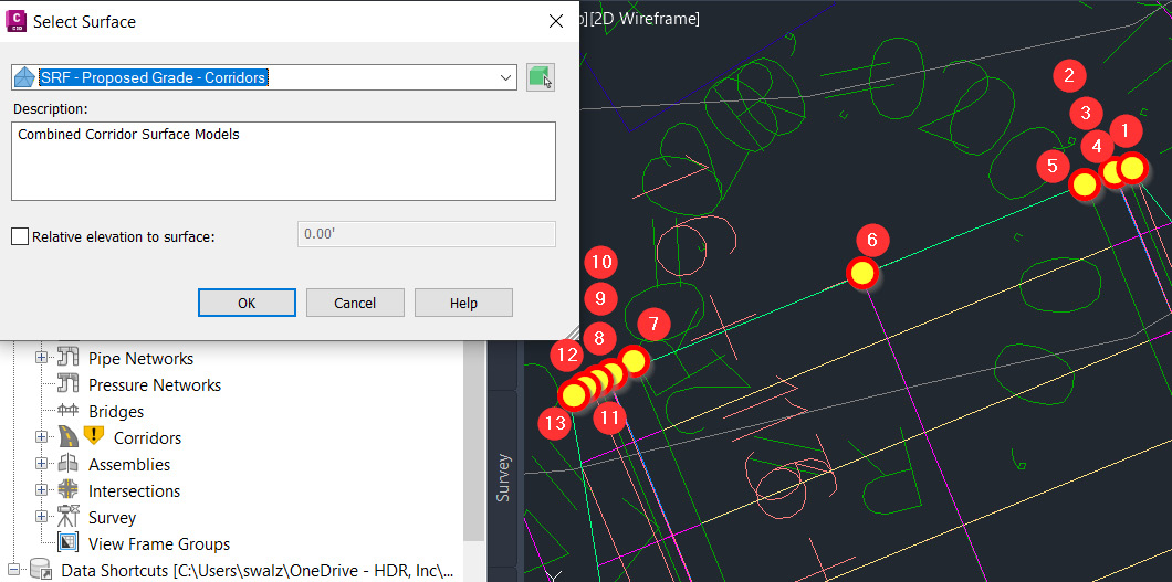
Figure 11.13 – Create Feature Line steps
With our feature line created and reading the elevations from our COR - Subdivision Main Road – Access Corridor model, let’s jump over to our assemblies again.
Looking at all of our assemblies created thus far, we can quickly determine that there is one assembly already created that most closely resembles the dead-end assembly that we need to apply at this location in our design.
You guessed it! It’s the Curb Return Fillets assembly that was automatically generated during our intersection design in Chapter 10, Roadway Modeling Tool Belt for Everyday Use.
Let’s go ahead and select the Curb Return Fillets Assembly baseline and initiate the AutoCAD Copy command to create a duplicate version of this assembly and place it on the right side of all assemblies displayed.
Once copied, we’ll want to make two modifications to this new assembly. The first modification will be to rename the assembly by selecting the baseline, pulling up our Properties dialog box, and changing the name from Curb Return Fillets to Dead End.
The second modification we’ll want to make is to remove the BasicLaneTransition subassembly attached to the left side of the assembly, with the final version appearing similar to that shown in Figure 11.14:
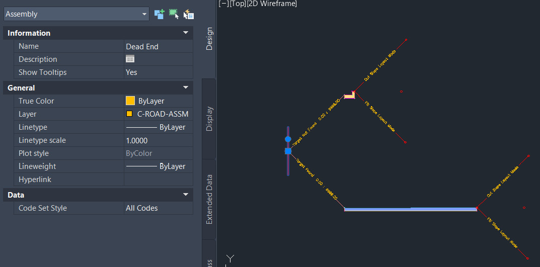
Figure 11.14 – Dead End subassembly
The final step we’ll take here will be to create a new Corridor model specific to our dead-end design. After selecting our Create Corridor tool within the Create Design panel in our Home ribbon, we’ll fill out the Create Corridor dialog box that appears as follows (also displayed in Figure 11.15) and click the OK button:
- Name: COR - Subdivision Main Road - Dead End
- Description: Dead End design at end of Main Road
- Corridor style: Basic
- Baseline type: Feature line
- Site: SIT – Proposed – Dead End
- Feature line: Dead End (we’ll need to click the box icon to select the new feature line we just created, at which point we’ll then be prompted to name said feature line, giving this Feature Line the name of Dead End)
- Assembly: Dead End
- Target Surface: <none>
- Set baseline and region parameters: Check the box
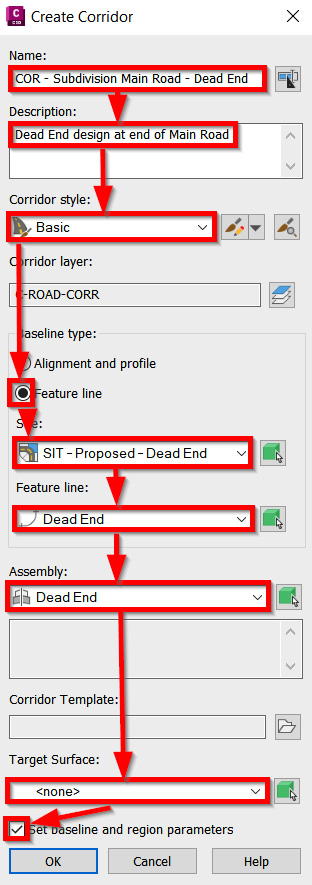
Figure 11.15 – Create Corridor dialog box (dead end)
Since we checked the box next to Set baseline and region parameters in our Create Corridor dialog box, a Baseline and Regions parameters dialog box will then appear. Using similar processes outlined in the previous section, we’ll want to apply horizontal and surface targeting to our COR - Subdivision Main Road - Dead End Corridor model as we had to all other Corridor models in our Grading Model.dwg file, with the final output looking similar to that shown in Figure 11.16:
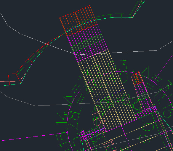
Figure 11.16 – Dead-end corridor design
With that, we will conclude our example of creating a dead-end corridor using the several different methods available to us in Civil 3D. Corridors come in many different forms, and the patterns and methods used to create one may not work for another.
Civil 3D allows for many different methods and intelligent tools to allow the creation of any corridor design needed. In the next section, we will dive into the design of an entrance.
Designing our residential subdivision main entrance
With the final piece of the corridor modeling to go, let’s jump over to our main entrance where our residential subdivision design meets with York Highway. As outlined in Chapter 10, Roadway Modeling Tool Belt for Everyday Use, to model out the intersection of our ALG - Subdivision Main Road – Access and ALG - Subdivision Side Road - Cul-De-Sac alignments, we’ll apply similar steps to design our intersection between our ALG – Existing York Hwy – FromSurveyPoints and ALG - Subdivision Main Road – Access alignments.
Going back up to our Create Design panel inside of the Home ribbon, we’ll activate the Create Intersection tool. Once activated, we’ll be asked at the command line to identify the intersection point where we’ll want to snap to the intersection of our ALG – Existing York Hwy – FromSurveyPoints and ALG - Subdivision Main Road – Access alignments, as shown in Figure 11.17:
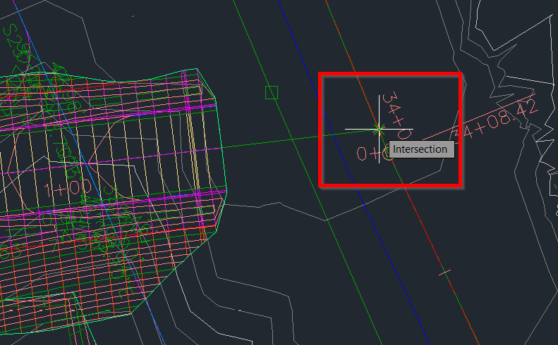
Figure 11.17 – Intersection design location
After clicking on the intersection point, Civil 3D’s Create Intersection dialog box will appear, starting with the General tab. We’ll want to fill out the fields as follows in our General tab (also displayed in Figure 11.18) and select the Next button at the bottom of the Create Intersection dialog box:
- Intersection name: INT – Subdivision Main Road – Entrance
- Description: Intersection of Subdivision Main Road and York Highway Alignments
- Intersection marker style: Intersection Marker
- Intersection label style: Basic
- Intersection corridor type: Primary Road Crown Maintained
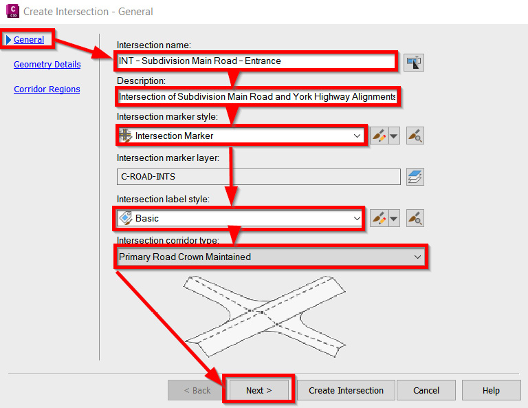
Figure 11.18 – Create Intersection dialog box | General tab
Next, we’ll fill out the fields in the Geometry Details tab as follows (also displayed in Figure 11.19), but will also make some slight adjustments to our Curb Return parameters:
- Create or specify offset alignments: Check the box
- Create curb return alignments: Check the box
- Create offset and curb return profiles: Check the box
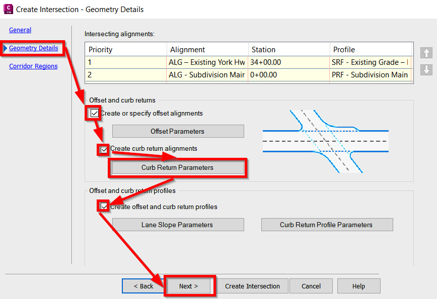
Figure 11.19 – Create Intersection dialog box | Geometry Details tab
Before selecting Next, we’ll want to make sure we select the Curb Return parameters option so that we can make some adjustments to the radii being applied at the entrance of our residential subdivision.
Once selected, we’ll see that the Intersection Curb Return Parameters dialog box appears, at which point we’ll want to change our default radius value from 25.00' to 50.00' for both SW - Quadrant and NW - Quadrant.
You may also notice a preview of where the currently selected quadrant will be applied within our design by showing a preview in Model Space (refer to Figure 11.20):
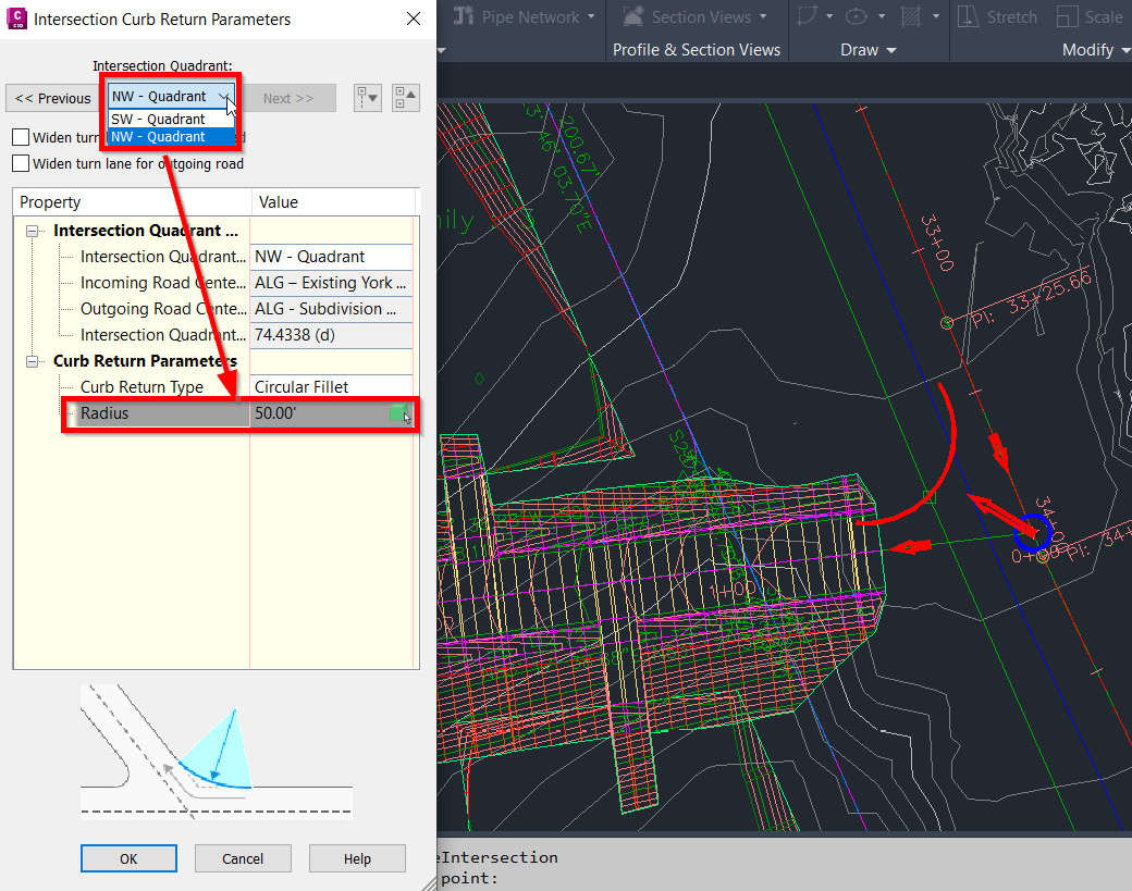
Figure 11.20 – Intersection Curb Return Parameters dialog box
After updating our radius values to both quadrants, we’ll then select the OK button in our Intersection Curb Return Parameters dialog box and then click the Next button back in our Create Intersection dialog box within the Geometry Details tab, bringing us to our final tab of Corridor Regions.
Within the Corridor Regions tab, we’ll fill out the values as follows (also displayed in Figure 11.21) and select the Create Intersection button at the bottom of the Create Intersection dialog box:
- Create corridors in the intersection area: Check the box
- Create a new corridor: Check the box
- Corridor Region Section Type: Accept all default assemblies being applied
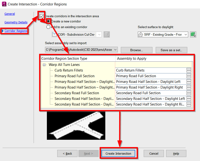
Figure 11.21 – Create Intersection dialog box | Corridor Regions tab
After selecting the Create Intersection button in the Create Intersection dialog box, our intersection Corridor model will be created similarly to that shown in Figure 11.22:
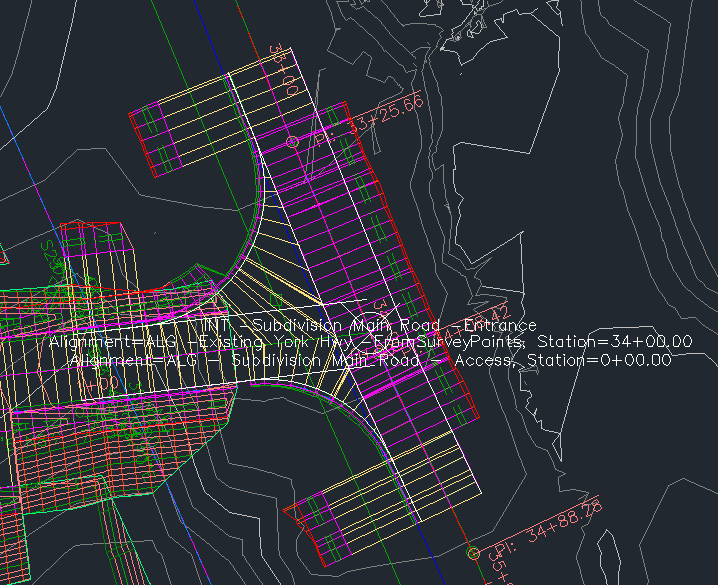
Figure 11.22 – Intersection design output at the main entrance
We’ll notice that in this view alone (refer to Figure 11.23), we have a bit of overlap going on with our new INT – Subdivision Main Road – Entrance Intersection model and our COR - Subdivision Main Road - Access Corridor model.
Let’s go ahead and select our COR - Subdivision Main Road - Access Corridor model and manually adjust the starting point by sliding our grip to the end of the INT – Subdivision Main Road – Entrance Intersection model, as shown in Figure 11.23:
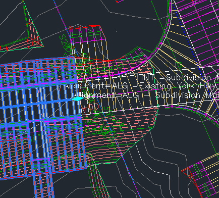
Figure 11.23 – New starting point for our COR - Subdivision Main Road - Access Corridor model
The second portion of the INT – Subdivision Main Road – Entrance Intersection model that will require a bit of cleanup involves the ConditionalHorizontalTargets subassembly. Now that we’ve essentially gone in and updated all of our assemblies to include the ConditionalHorizontalTarget subassembly, including those used to generate our Intersection models, we’ll need to make sure that at least one target is defined in order for the daylighting to properly finish throughout the INT – Subdivision Main Road – Entrance Intersection model.
Since no actual driveways are placed within the extent of our INT – Subdivision Main Road – Entrance Intersection model, we’ll want to make sure that we select only one driveway polyline that is not perpendicular to any of our anticipated projections.
That said, we may need to select a couple of different driveway polylines based on the anticipated horizontal projection to make sure that our subassemblies follow the Not Found application of our assemblies. Once all have been identified and we update our INT – Subdivision Main Road – Entrance Intersection model, we should have our design appear similar to that shown in Figure 11.24:
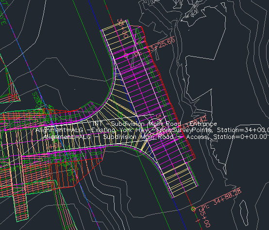
Figure 11.24 – Final intersection design output at the main entrance
With all of our Corridor and Intersection models updated and refined, we’ll now want to create Corridor Surface models from our Corridor models by running through the steps outlined in Chapter 10, Roadway Modeling Tool Belt for Everyday Use.
Once all Corridor Surface models have been created, we’ll then want to update our SRF - Proposed Grade – Corridors Surface model by pasting all remaining Corridor Surface models in and rebuilding our Surface model, with the final result looking similar to that shown in Figure 11.25:
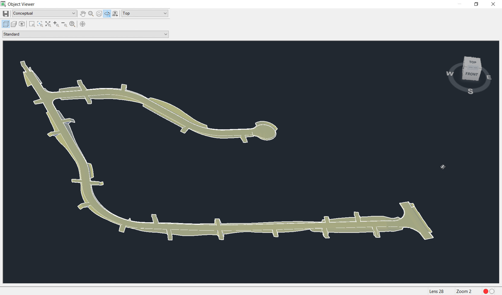
Figure 11.25 – Final SRF - Proposed Grade – Corridors Surface model
To complete our Surface model within our residential subdivision design, we’ll now want to merge our SRF - Proposed Grade - Corridors and our SRF - Proposed Grade – Building Pads Surface models into one comprehensive Surface model so that we can accurately design our drainage utility network in Chapter 12, Utility Modeling Tool Belt for Everyday Use.
That said, let’s go ahead and create a new surface using similar steps outlined in Chapter 6, Chapter 6, Surfaces - The First Foundational Component to Designs within Civil 3D, and Chapter 9, Land Development Tool Belt for Everyday Use, and place our new Surface model within our Proposed subfolder within the Surfaces category inside of our Toolspace | Prospector tab.
When creating our new surface, we’ll give it a Name value of SRF - Proposed Grade - Residential Subdivision and a Description value of Combined Corridor and Building Pads Surface Models. After it’s created, we’ll paste in both our SRF - Proposed Grade - Corridors and our SRF - Proposed Grade – Building Pads Surface models to create one comprehensive Surface model, with the final output looking similar to that displayed in Figure 11.26. The order in which we paste each is important in this example. First, we will paste our building pad surface and then the corridors:
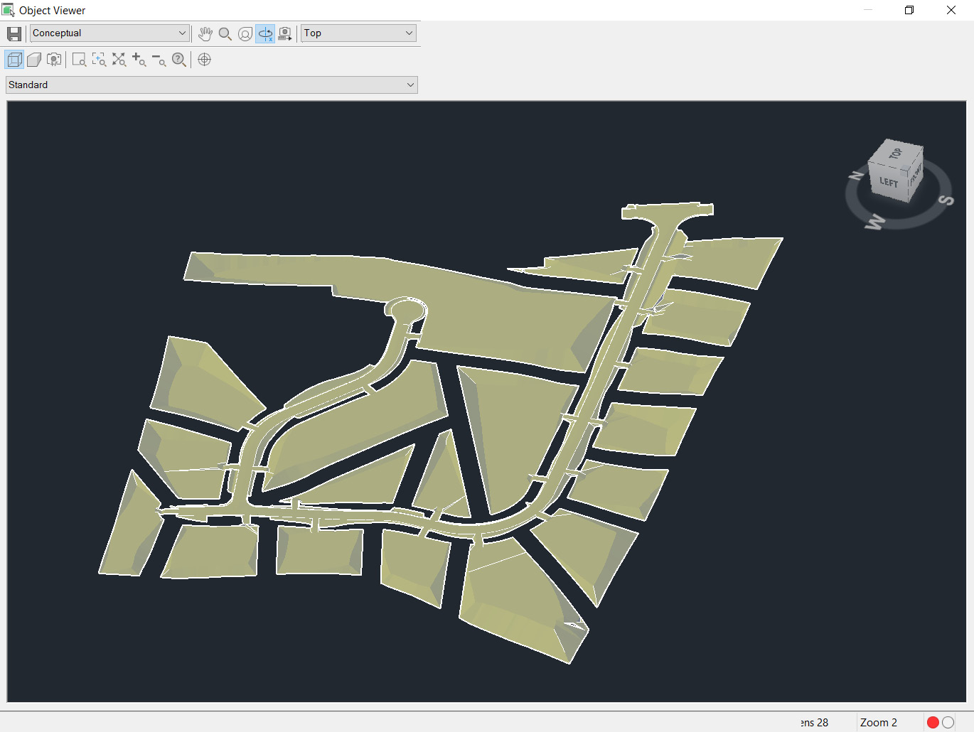
Figure 11.26 – Final SRF - Proposed Grade - Residential Subdivision Surface model
The last step we’ll take is to create a data shortcut of our SRF - Proposed Grade - Residential Subdivision Surface model. We’ll want to use this new Surface model to base our drainage utility design on in Chapter 12, Utility Modeling Tool Belt for Everyday Use, to ensure that we are properly draining our residential subdivision design during rain events.
Summary
As we worked through this chapter, we have been able to make significant progress toward shoring up our roadway and overall grading design throughout our residential subdivision design. We’ve expanded our understanding of how and why assemblies and subassemblies are considered to be the building blocks of all transportation-focused designs.
We also learned many additional settings and intricacies involved with furthering our roadway design by applying different site requirements and conditions so that our Corridor models can automatically make decisions within our design. We’ve also learned how we can merge Surface models from our land development and roadway modeling tool belts to create one comprehensive and fully integrated Surface model.
In our next chapter, we’ll replace our roadway modeling tool belt with our utility modeling tool belt to finish up our residential subdivision design. As we understand utility modeling tools available to us in Civil 3D, we’ll be able to design a storm drainage network, a sanitary sewer network, and a domestic water network that will not only support our new residential subdivision but also tie into the existing networks along York Highway.