
4
Configuring Survey Data with Civil 3D
As we have begun to develop a fundamental understanding of how Civil 3D operates and have reviewed in a bit of detail many of the foundational settings, configurations, and workflows necessary to begin a design project within the Civil 3D environment, we can now start to put these skills to the test and into practice.
Typical civil design projects tend to begin with the development of a Survey Model representing your site’s existing conditions. In this chapter, we will demonstrate the start of bringing in existing survey data with proper formatting and how to establish an accurate depiction of the yet-to-be-designed project site.
That said, key topics that we will cover in this chapter include the following:
- Survey setup
- Introduction to the Survey Toolspace
- Existing conditions display settings
- Survey workflow overview
- Analyzing your existing conditions
Additionally, starting with this chapter, we will begin to use a real dataset to get some hands-on training as we learn the different tools that Civil 3D has to offer us, and how we can leverage them for real-world design applications. We will begin by using the dataset found in our Practical Autodesk Civil 3D 2024Chapter 4 subfolder, starting with the file titled Survey Model_Start.dwg.
Technical requirements
It’s important to note Autodesk’s Civil 3D can oftentimes be very taxing on your computer. There is a lot of processing that goes on with modeled design elements, even in the background, that enables the dynamic (connected) capabilities to occur throughout the Building Information Modeling (BIM) design lifecycle.
In turn, there are many technical requirements that need to be considered to allow Autodesk’s Civil 3D to operate at its full potential. We’ll review the minimum requirements that Autodesk recommends, with a few of my suggestions added to increase efficiency and speed throughout the BIM design process:
- Operating system: 64-bit Microsoft Windows 10
- Processor: 3+ GHz
- Memory: 16 GB RAM (I suggest going with either 64 GB or 128 GB)
- Graphics card: 4 GB (I suggest going with 8+ GB)
- Display resolution: 1980 x 1080 with true color
- Disk space: 16 GB
- Pointing device: MS-Mouse compliant
The exercise files for this chapter are available at https://packt.link/UoiPn
Survey setup
Setting up your Survey Model properly from the get-go can be compared to setting the foundation for a house. All design elements will essentially be built on top of—and will need to reference in—various methods, the Survey Model depicting the existing built environment.
In this section, we’ll run through the basics of Civil 3D survey tools and get a clearer understanding of how we can leverage each to configure or set up our Survey Models. This section will act as our inspection phase of the survey to investigate the conditions of the drawing, including ensuring the geolocation has been properly set, determining how the existing conditions were modeled, and checking the entire drawing for miscellaneous drawing elements to ensure the file is neat and ready to be used as the foundation of our design.
Let’s go ahead and open up our Survey Model_Start.dwg file. Once it’s open, you should see your overall existing conditions, or Survey Model, being displayed, as shown in Figure 4.1:
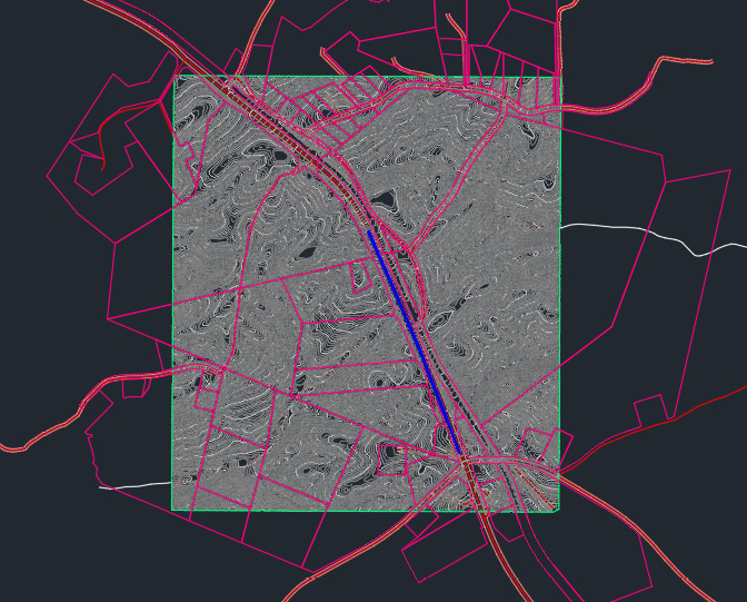
Figure 4.1 – Survey Model
If we go ahead and launch our Toolspace (accessed through our Home ribbon) and select our Prospector tab within the Toolspace, we will begin to see some Civil 3D modeled objects already present within our file, as shown in Figure 4.2:
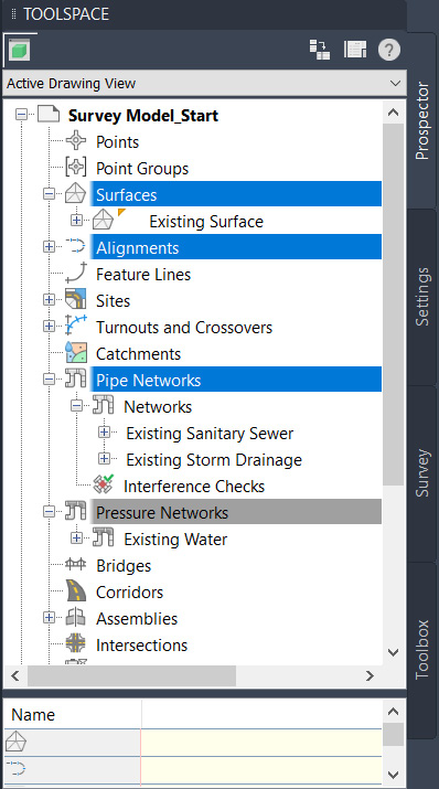
Figure 4.2 – Modeled objects in Toolspace
These Civil 3D objects consist of Surfaces, Alignments, (gravity) Pipe Networks, and Pressure Networks). Each of these Civil 3D objects within our prospector can be expanded by clicking on the + icon next to each object for a more detailed breakdown of the elements that define each object.
The next step I recommend taking before going any further is ensuring that the coordinate system projection has been properly configured for the Survey Model. As discussed in Chapter 2, Setting up the Design Environment and Setting Your Next Project Up for Success, this is a critical step that should be performed to provide you with the assurance that your design is projected into real-world coordinates.
That said, let’s go ahead and select the Settings tab on our Toolspace. Right-click on the drawing name listed at the top and select Edit Drawing Settings.
Once it’s selected, we will be presented with our Drawing Settings dialog box where we can set (or confirm, in this case) that our Survey Model has been assigned a coordinate system, as shown in Figure 4.3:

Figure 4.3 – Drawing Settings coordinate system
Now that the coordinate system has been confirmed, let’s click on OK at the bottom of the Drawing Settings dialog box and go back up to our ribbon toward the top.
Let’s select the Geolocation ribbon, go to our Online Map section, and change our Map Off selection to Map Aerial. Once this has been changed, an aerial image of our site and surrounding areas will be displayed as a background behind our Survey Model, as shown in Figure 4.4:
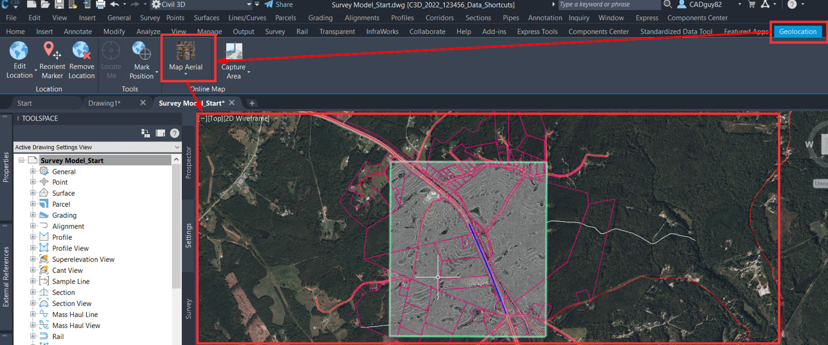
Figure 4.4 – Map Aerial from the Geolocation ribbon
It’s important to note that if the coordinate system were set up to a different projection and we then proceeded with toggling on the Map Aerial selection, we would be presented with a completely different map associated with that projection and the map would no longer line up with our site.
That said, a quick visual inspection can confirm that the coordinate system that the file has been associated with is in fact the true projection of the site, essentially meaning that we’re good to go and ready to start proceeding with continued Survey Model setup in preparation of our design for this project.
Next, let’s investigate the elements contained within the drawing. At first glance of the Toolspace, we saw Civil 3D recognized the modeled components of a surface, pipe networks, a pressure network, and some alignments. Let’s run through a quick exercise to inspect these elements further.
Survey files can come in many shapes and forms. The exercise file we will be using contains modeled Civil 3D components that are dynamic, just as Civil 3D would prefer, and would be able to fully leverage further into design. However, files do not always come like this. A majority of survey files received come as 2D linework drawings with flat contours and symbols for utilities and more.
Civil 3D is, to be put frankly, a three-dimensional program, and many who utilize it prefer it to remain as a 2D program. So, when receiving files, do not be surprised when you see elements flattened with their elevation set to 0'. What can also happen is some elements have their elevation set to 0' while others have been missed, so their linework may be at 0' as well as 800', or whatever the local elevation of the region is. This is why it is so vital to inspect your survey drawings thoroughly and understand how they were generated and what you need to do to be successful with them.
Now that we have inspected the modeled elements and ensured the geolocation is accurate, let’s walk through some simple housekeeping of the drawing to ensure it is ready to be used for our design.
To verify that all objects in our Survey Model are geolocated and in close proximity of our site, we can perform a simple Zoom Extents of our file to quickly see if any objects fall outside of our site, or are significantly far away. If objects are far away from our site, we can select those objects using the simple Window Selection, right-click with our mouse, and select Properties so that we can identify which types of objects they are, along with any additional information associated with them.
Occasionally, surveyors and engineers will place various symbology, blocks, annotation, and so on on the side so that they can quickly access these objects to populate the Survey Model, and then forget to remove them later on from the file before handing off to the design firm. Although these remnants typically are not a cause for concern, it is recommended to remove these objects if they are not contributing or adding any value to our Survey Model or design moving forward. This way we are keeping things clean from the start.
Quick exercise with zoom extents
Do an exercise by turning on Properties to the right of the screen and select elements in the drawing, noting in Properties what you have selected, checking for miscellaneous linework, and so on.
To conclude this section, the survey files you work with are again foundational to the design moving forward. The more accurate the survey file is, the more accurate and confident you can be in your design. It is vital to always inspect your survey files, whether they come from your in-house surveying department or an outside surveying firm.
Each group conducts itself differently and uses different nomenclature and techniques for generating these legally binding documents for use in projects. You may not always receive the most up-to-date Civil 3D drawing with modeled components and existing pipe networks modeled. Most of the time, you can expect to receive a flat 2D drawing with contours and basic notations for utilities and materials.
Running through the files you receive and fully inspecting all the conditions listed previously can save you time and headaches before you begin to design and realize down the road that something is off that wasn’t seen earlier. With this first section complete, let’s move on to further understanding Civil 3D’s capabilities with surveying.
Introduction to the Survey Toolspace
Oftentimes, the Survey tab within our Toolspace can help us better manage survey data and settings within our project files. It’s important to note that survey data and settings being managed in this space are applied to our entire Civil 3D project and are not drawing-specific.
Also, it’s very important to note that although this functionality can come in handy from a surveyor standpoint, it is not typically utilized from a design standpoint. Nevertheless, let’s jump into how to access the Survey Toolspace and understand some of the capabilities contained within.
To access it, we’ll need to go back to our Toolspace on the Home ribbon and select our Survey tab along the right side of our Toolspace, as shown in Figure 4.5:
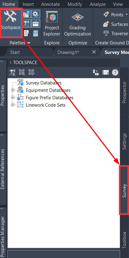
Figure 4.5 – Survey tab in Toolspace
Once presented with the Survey Toolspace, we now have access to configure Survey Databases, Equipment Databases, Figure Prefix Databases, and Linework Code Sets, all by simply right-clicking on any of these functions listed out and selecting New.
Here’s a quick overview of what each of these selections allows us to do:
- Survey Databases: Allows the configuration of survey-related networks, including control points, non-control points, known directions, observations, setups, and traverse definitions, along with figures and survey points
- Equipment Databases: Allows the input of specifications related to the equipment used to survey your site
- Figure Prefix Databases: Provides the ability to set the layer that figures are placed on within our Survey Model
- Linework Code Sets: Allows the mapping of field codes utilized in the data collector used by the survey field crew
Through these selections, surveyors are able to make connections to data collectors used in the field to import and convert data into real geometry within Civil 3D. As more data is collected, surveyors can continue to update the geometry by either manually updating or hosting a dynamic link to the project that will push updates automatically into your files.
From a designer perspective, we typically get involved after all of the survey data has been converted into geometry where the surveyor will then hand off the Survey Model (in our case, this will be our Survey Model_Start.dwg file) to the engineer/designer where we can then clean it up to conform to any display standards required for the project.
In this section, we briefly dived into the detailed functionality of the Survey Toolspace and were able to get more of an understanding of all the capabilities Civil 3D can offer the surveying industry. Since this book is intended to focus on design principles and workflows, we will not need to explore them in more detail as our intention for design differs.
For now, we know where to access the tools if the need may arise and we understand how we can affect the survey if needed, but the best practice for working with survey files is to understand them and take stock of what was delivered and not to modify the drawing at all lest we risk modifying the existing conditions incorrectly.
Next, we will explore the settings that control the appearance and characteristics of our existing conditions. With an understanding of what a survey file contains, as well as all that is entailed when working with a survey file, we can apply what we learned to adjust the file visually for a better understanding of our design strategy without modifying the actual survey file that was delivered to us as the designer.
Existing conditions display settings
Now that we have received the Survey Model_Start.dwg file from the surveyor, we can begin looking into ways to clean it up to meet our project design and display requirements. It is important for us to understand what is advised to do and not to do when working with survey files.
Earlier, we inspected all the aspects of our drawing to ensure its integrity, but now we will be exploring how we can modify its appearance to better understand our existing conditions without risking the modification of the actual drawing itself.
If you have not done so already, let’s go ahead and open the Survey Model_Start.dwg file contained within our Practical Autodesk Civil 3D 2024Chapter 4 dataset folder.
Once opened, we’ll then click on the Manage ribbon and select our Import icon in the Styles section on the ribbon, as shown in Figure 4.6:
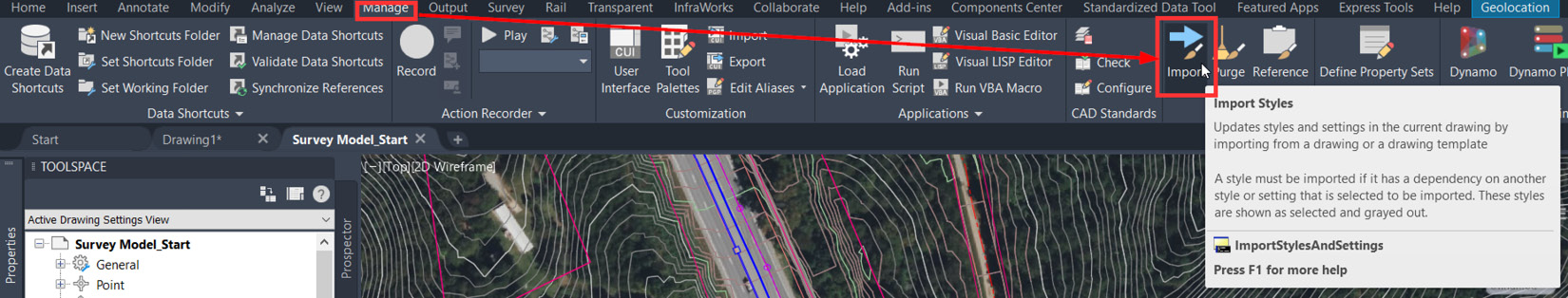
Figure 4.6 – Import styles
We’ll then be prompted with a dialog box to search for the template file that we’d like to import. At this point, we’re going to want to locate and import a client-based Civil 3D template, or a company Civil 3D template, if available.
If not, we can always start off with the standard Imperial template that comes with standard Civil 3D installations to use as a foundation for us to begin developing our own company Civil 3D template moving forward.
With that, let’s go ahead and navigate to our local directory at C:Users eplacewithusernameAppDataRoamingAutodeskC3D 2024enuTemplate and select our _Autodesk Civil 3D (Imperial) NCS.dwt file to import basic styles into our drawing, as shown in Figure 4.7:

Figure 4.7 – Drawing templates
We’ll next be prompted to identify which label, table, and display styles from the Civil 3D template we’d like to import into our current drawing. Feel free to expand any of the sections to get a better understanding of what will be included in the importing process.
However, since we’re essentially starting from scratch, let’s just go ahead and check the box at the top that selects all styles to import (as shown in Figure 4.8) and click on OK:

Figure 4.8 – Selecting all styles to import
Now that we have a great foundation to start with, we can now begin standardizing and assigning display styles to our modeled survey elements. We’ll now go back to our Prospector tab in our Toolspace, expand the Surfaces category, right-click on Existing Surface, and select the Surface Properties… option, as shown in Figure 4.9:
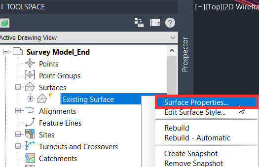
Figure 4.9 – Accessing Surface Properties
We will be presented with our Surface Properties dialog box, shown in Figure 4.10:

Figure 4.10 – Surface Properties dialog box
In the Surface Properties dialog box, we can modify the name, description, and default styles associated with the surface. The Description input is often overlooked, but it’s definitely good practice to provide some level of description as it relates to how and/or when a modeled object was constructed.
You’ll notice the Default Styles section has two options for display: Surface style and Render Material. The Surface style option will be the most common style used for plan view purposes and is applied whenever the Wireframe visual styles are applied.
The Render Material option will only be displayed when in a rendered state or when a realistic visual style is applied. For now, let’s keep the Surface style option selected as Contours 1’ and 5’ (Background) and the Render Material option as ByLayer.
To dig a little deeper into the display style settings, let’s go ahead and select the down arrow icon directly next to the Surface style selection. You’ll notice a drop-down list of options made available where we can do the following:
- Create New: Allows you to create a new display style from scratch and refine the settings within
- Copy Current Selection: Allows you to make a copy of the current selection and refine the settings within the new version
- Edit Current Selection: Allows you to refine the settings within the currently selected display style
- Pick from Drawing: Allows you to select another display style of a similar object within your current file and apply it to the current object
Let’s go ahead and select the Edit Current Selection option, as shown in Figure 4.11:
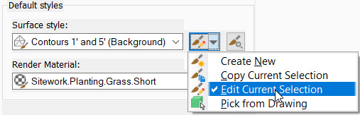
Figure 4.11 – Edit Current Selection: surface style
Once selected, we’ll then be presented with a Surface Style dialog box that allows us to refine the settings of the currently selected surface display style—in this case, Contours 2 and 10 (Background).
Once launched, we’ll start off by going into the Display tab (most likely, we’ll already be in the Display tab) and verify that our settings in the Plan, Model, and Section views are as we would like them to appear.
Remembering that the name of this particular display style is Contours 2’ and 10’ (Background), we’re going to want to keep the Major (10’) and Minor (2’) contours toggled on, but may want to turn off the Border display, as shown in Figure 4.12:
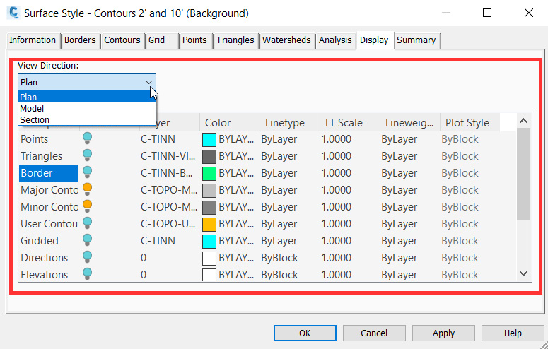
Figure 4.12 – Surface Style display settings
We also have the ability to change the Layer, Color, Linetype, Linetype Scale, Lineweight, and Plot Style options in the additional columns as needed. In the Out of the Box template that we imported containing the styles, all standard layers associated with these styles have been imported into our current file as well.
There may be some minor adjustments that you may want to implement with regard to the layer naming conventions, but it’s important to note that the layers being imported, and associated with the styles themselves, are in alignment with layer naming conventions outlined in the National CAD Standard (NCS).
Although you may be required to make adjustments to the layer assignments and naming conventions, it’s recommended that the additional columns (Color, Linetype, and so on) all remain as is to ensure that the controlling display is dictated by the layer assigned to those individual components and the associative properties.
Once we’re comfortable with how our Display settings are being applied to our surface object in each view direction, we can make additional adjustments to the settings of the surface style by switching into any of the tabs listed along the top, as shown in Figure 4.13:

Figure 4.13 – Surface Style settings
The Information tab provides a brief overview of the name, description, and some additional details about the surface style. The Borders, Contours, Grid, Points, Triangles, Watersheds, and Analysis tabs allow for further defining some of the display settings associated with each component of the surface display. The Summary tab is essentially a quick access that displays all tabs and settings available throughout the various tabs, and also allows us to modify them in one consolidated location.
Now that we have a good idea of how we can update, modify, and refine our display settings associated with surfaces, we can apply similar concepts across all other Civil 3D-modeled objects within our Survey Model.
Going back to our Toolspace and selecting our Prospector tab, we can see that we also have Alignments, Pipe Networks, and Pressure Networks created in this file as well. If we were to select the modeled objects directly in our Model space, right-click, and select Edit (object) Style, we would be presented with similar dialog boxes that would allow us to further define and apply display settings associated with our objects.
With this section, we learned the importance of understanding our survey file so that we can next understand what we can do to customize it for our team’s unique needs for creating our design further down the road. Survey files can vary greatly from group to group, and with Civil 3D, we have the ability to keep it in our company’s design standards to make it easy to use when working, as well as producing final documentation down the road.
In the next section, we will begin actually working with the survey file and integrating it into our design documents, as our drawings will all begin to link and build upon each other. This is incredibly important, as taking the time to return to previous issues or missed information can be costly to a design team and can lead to faulty designs if not noticed soon enough.
Survey workflow overview
After going through and applying our various objects and settings within our Survey Model, we can now start to begin thinking about two major steps in our design workflow: beginning our design and syncing updates to our master project—or company—Civil 3D template.
To set up our Survey Model to be incorporated into our design models moving forward, we’ll go ahead and follow the steps outlined in Chapter 3, Sharing Data within Civil 3D in the Setting the working folder, Associating a project to the current drawing, and, finally, Creating data shortcuts topics for all Civil 3D modeled objects in the Survey Model file.
From a Civil 3D template standpoint, we’re going to want to make sure we continue to update our project-specific, or company-wide, Civil 3D template. That said, let’s go ahead and perform a SAVEAS command (type this in the command line) to save our current file as a drawing template.
When the Save Drawing As dialog box appears, give it a descriptive name and change the Files of type option to AutoCAD Drawing Template (*dwt), as shown in Figure 4.14:
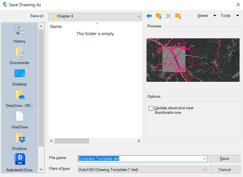
Figure 4.14 – Save Drawing As dialog box
After a descriptive name has been given and the Save button has been selected, we’ll be presented with a Template Options dialog box where we can add some additional settings and a Description option for tracking purposes and to provide some additional clarification for the application/uses of the template, as shown in Figure 4.15:
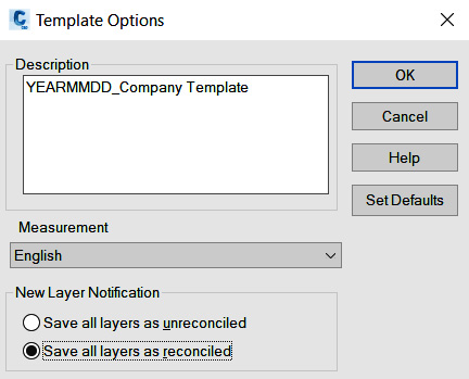
Figure 4.15 – Civil 3D Template Options dialog box
Once saved/created, you’ll notice that the current file open is now your survey template, and no longer your Survey Model that we’ve been working on. We can tell this by looking back at the top of our Civil 3D session and noticing that the name indicated at the top now reflects the name of the file we just saved, with a .dwt extension, as shown in Figure 4.16:

Figure 4.16 – Current file open
The next step we’ll take in our drawing template is to select everything in Model space (or press the Alt + A keys on your keyboard to select all), and then type ERASE at the command line (or simply hit the Delete key on your keyboard).
By doing this, we are essentially keeping our initial drawing template as clean as possible without containing any actual Civil 3D (or AutoCAD) objects in it. From a drawing template perspective, we really only want this file to contain the necessary display styles and settings that can be imported into our files moving forward.
For any updates we intend to make to the drawing templates from here on out, we’ll take a slightly different approach by opening our drawing template, using the Import Styles and Settings workflow mentioned earlier in this chapter, and perform a SAVEAS to overwrite the file.
With this section, we have been able to utilize some of the incredibly powerful workflows of Civil 3D by referencing drawings from outside sources that utilize its styles and settings, but we can also frame them within our company’s templates to display them as our team has agreed upon and to highlight features for ease of use in drawing creation, as well as plotting when the time comes to issue drawings.
This is not only highly favorable to our design process for working more efficiently, but it is also a large time saver versus previous ways that required redoing many of the elements manually and ensuring nothing was missed before moving on to the design.
Furthermore, you should have acquired a new skillset for customizing a survey file with your company’s standards and templates without being at risk of modifying the existing conditions given to your group. This can be applied in later projects if needed for customers that require specific elements on specific layers or plotted in specific ways.
So, with that, multiple templates can be created and chosen as necessary as different projects from different clients arise, and you and your team can remain confident in your production level despite the varying projects being designed.
Analyzing your existing conditions
There are many ways we can begin inspecting and analyzing our existing conditions model. These methods can certainly be carried throughout our design lifecycle and applied to design models as well. Although we’ll get into some more complex ways of analyzing our existing conditions model over the next few chapters, let’s start out with some very simple methods that anyone just starting off can pick up.
Going back to our Survey Model_Start.dwg file, let’s begin by taking a good look at our Surface model in a three-dimensional view to make sure that our existing surface at least appears to be accurate from a visual standpoint.
To perform this quick validation, we can simply select our existing Surface model in Model space by right-clicking and selecting the Object Viewer… option, as shown in Figure 4.17:
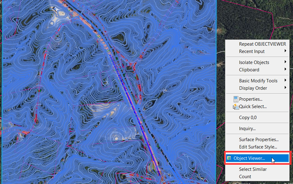
Figure 4.17 – Object Viewer selection
Once selected, an Object Viewer dialog box will appear where we can update Visual Display Styles, Orientation, and Viewing Distances options, as shown in Figure 4.18:
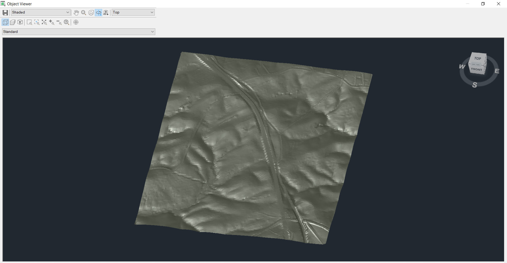
Figure 4.18 – Object Viewer with surface display
In the top left-hand corner of our Object Viewer dialog box, you’ll notice a number of fields and tools available to us where we can fine-tune and modify our current display. On the top row, going from left to right, we have the following tools and options available to us (a detailed display of this row is shown in Figure 4.19):
- Save Image: Allows us to save/export the current view displayed in Object Viewer to an image file
- Visual Styles: Allows us to apply AutoCAD visual styles (preset and custom defined) to our current view displayed in Object Viewer
- Pan Realtime: Allows us to pan, or shift, our current view displayed in Object Viewer
- Zoom Realtime: Allows us to zoom in/out of our current view displayed in Object Viewer
- Steering Wheel: Allows us to quickly access many navigational tools to modify our current view displayed in Object Viewer
- Constrained 3D Orbit: Allows us to orbit three-dimensionally around our current view displayed in Object Viewer
- Adjust Distance: Allows us to adjust the perspective projection of our current view displayed in Object Viewer (note that this can only be adjusted if Perspective Setting is toggled on; refer to the second row of tools, also shown in Figure 4.20)
- View Control: Allows us to apply a preset view direction to our current view displayed in Object Viewer:
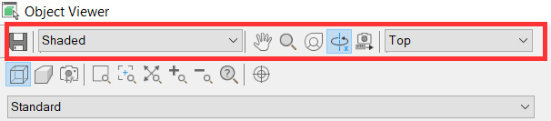
Figure 4.19 – Object Viewer with surface display
In the second row, going from left to right, we have the following tools and options available to us (a detailed display of this row is shown in Figure 4.20):
- Parallel View: Sets the current view displayed in Object Viewer to be parallel to our objects
- Perspective View: Sets the current view displayed in Object Viewer to be angled to our objects
- Lens Length: Sets a zoom factor to Perspective View (not available in Parallel View)
- Zoom Window: Allows us to zoom into our current view displayed in Object Viewer using the window option
- Zoom Center: Allows us to center our current view displayed in Object Viewer; this is done by clicking with our mouse on the intended center of our display
- Zoom Extents: Allows us to quickly zoom to the extents of all objects displayed in our current view in Object Viewer
- Zoom In: Allows us to zoom in to our current view displayed in Object Viewer
- Zoom Out: Allows us to zoom out in our current view displayed in Object Viewer
- Zoom Factor: Allows us to apply a zoom factor to our current view displayed in Object Viewer
- Set View: Allows us to apply our current view displayed in Object Viewer to our view being displayed in Model space:
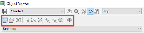
Figure 4.20 – Object Viewer with surface display
With that overview, we should feel comfortable moving forward with rotating and viewing our modeled geometry within Object Viewer. Using the tools discussed, feel free to navigate your model within the Object Viewer dialog box as you see fit. Performing a visual inspection can also be done directly in the Model space, but it is not recommended as the design files are large files and are very graphic intensive, which can cause your system to freeze or crash, thus risking a loss of work.
This is why it is recommended to perform a visual inspection with Object Viewer as it is much less graphicly intensive on your system. Some items that I typically look for when visually inspecting my Surface model would include the following:
- Verification of high/low points
- Breakline locations where curb lines, edge of pavements, retaining walls, shorelines, ditches/channels, and so on may be present on-site appear to be located accurately, and our Surface model reflects these more drastic changes in grade/slope/elevation
- Surface anomalies
- Holes or missing data
- All project data needed has been captured to complete the design properly
Once we’ve been able to visually inspect our modeled geometry, we can close out of Object Viewer and begin analyzing our pipe networks, pressure networks, and centerlines that reside in our Survey Model_Start.dwg file.
With that, let’s go ahead and select our pipe networks, pressure networks, and Surface model all at once. To do so, instead of selecting these objects in our Model space, let’s use the following steps to select these modeled objects:
- Launch our Toolspace.
- Select our Prospector tab.
- Expand Surfaces and right-click on our existing surface.
- Choose the Select option.
- Expand Pipe Networks.
- Expand Networks.
- Right-click on our existing Sanitary Sewer Gravity Network.
- Choose the Select option.
- Right-click on our existing Storm Drainage Gravity Network.
- Choose the Select option.
- Expand Pressure Networks and right-click on Existing Water.
- Choose the Select option.
Now that we have selected all three of these modeled objects from within our Prospector (Surfaces, Pipe Networks, and Pressure Networks), we can now right-click in Model space and select the Object Viewer option again, the same as we did earlier in this section while inspecting our Surface model alone.
As we pull up our Object Viewer now and navigate around our model, we can verify that our modeled geometry is located properly and there are no glaring conflicts that appear (visually) within our model at this time (refer to Figure 4.21):
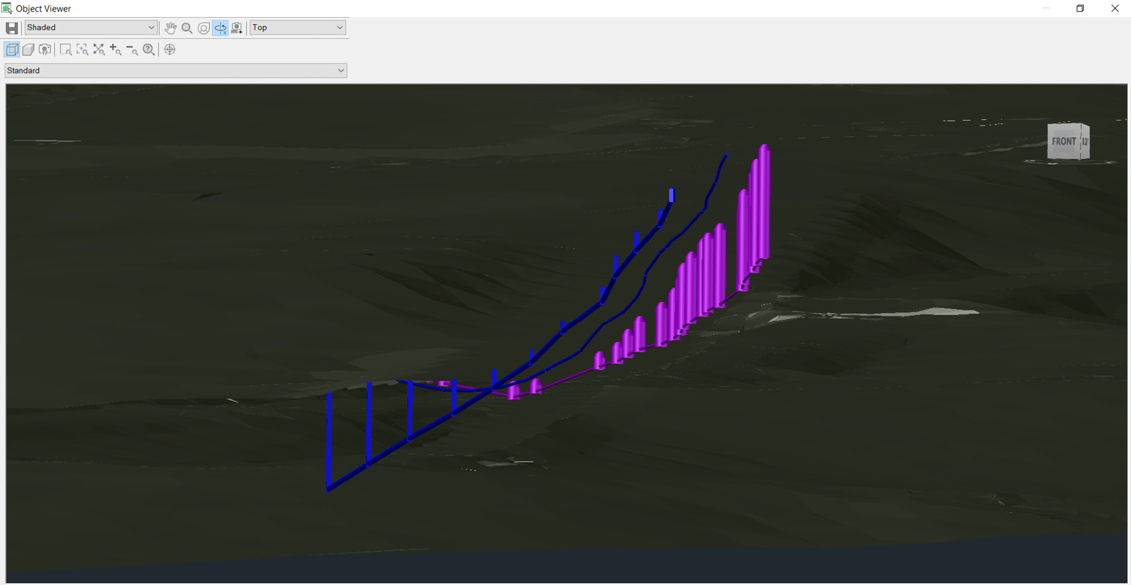
Figure 4.21 – Object Viewer with multiple objects in our display
When it comes to pipe networks and pressure networks, some items that I typically look for when visually inspecting in Object Viewer would include the following:
- Gravity pipe connections to structures
- Pressure pipe connections to fittings and appurtenances
- Presence of any clashing gravity and pressure pipes
- Quick inspection to verify that all gravity and pressure pipe networks are in fact under the Surface model as expected
- Gravity structures, and some pressure appurtenances, are at grade when viewing our Surface model as well
Note
It’s important to note that we are not necessarily limited to viewing only one type of object at a time in our Object Viewer. We can certainly select everything in our drawing at any given time and view all 2D and 3D objects in our Object Viewer.
Now that we’ve had a chance to visually inspect and analyze our model a little bit, we should begin to feel a bit more comfortable with how our Survey Model_Start.dwg file has been constructed, along with the modeled geometry contained within.
Summary
At the present time, we have now established all the foundational components to successfully set up our project and are now prepared to begin our design. As we progress through the remaining chapters, we’ll continue to revisit the steps of updating our project (or company) drawing template to make sure that we have an even sturdier foundation when we start our next project design.
Granted—in this example, we were in some ways afforded a bit of a lay-up in the sense that the Survey Model we started with had almost everything modeled and displayed as we would hope.
Many surveyors are very well versed in Civil 3D, and this is the type of Survey Model composition one can typically expect to receive. Unfortunately, that isn’t always the case, and designers will occasionally be required to piece survey data together and construct the models within survey points.
With that, in our next chapter, we’ll get a better understanding of how we can leverage points from a survey perspective, along with the Line and Curve tools that can be leveraged in parallel. Although these tools are not used very often in our day-to-day design workflows, this will give you an idea of some more of the powerful tools that are available to us with Autodesk Civil 3D.
This will also prepare us in the event that we will be required to compose our Survey Models from points alone.