
14
Automating Sheet Creation
Up to this point, we’ve taken all steps necessary to generate a Residential Subdivision design that we feel comfortable with, all while learning all of the design and analysis tools that are available to us within Civil 3D. We’ve also gained the assurance that all modeled objects are located where they should be and as we intended to conform to design standards and regulations.
With our Residential Subdivision design all modeled and wrapped up, we can now move on to understanding how we can leverage some automated workflows to set up our construction drawings by using Civil 3D’s Plan Production tools. Utilizing these tools will provide a new level of consistency and efficiency to us throughout the entire project design life cycle with its dynamic capabilities. This will essentially be the final step that we’ll want to take before submitting our design as part of the digital delivery process.
Historically, this effort has begun much earlier on in the design process, typically just before a Conceptual Design review. However, as the modeling process becomes more intricate, and technology advancements continue to increase the possibilities of reviewing our models in place of sheets, we must spend more time and effort upfront ensuring that our models are truly representative of our design and that we maintain dynamic linking between as many modeled objects as possible to minimize risk and reworking later on down the road.
All that said, in the chapter, we’ll cover the following areas:
- Automating Plan Sheet creation
- Automating Plan and Profile Sheet creation
- Automating Cross Section Sheet creation
With that, let’s go ahead and open up Civil 3D, or go to the Start screen if it’s already open, and create a new drawing using similar steps to those outlined in Chapter 7, Alignments –The Second Foundational Component to Designs within Civil 3D. We can use our Company Template File.dwt file located in Practical Autodesk Civil 3D 2023Chapter 14 and select Open in the lower right-hand corner of the Select Template dialog box. Once our new file has been created, we’ll want to save it as a Site Plan Sheets.dwg file to Practical Autodesk Civil 3D 2023Chapter 14Sheet.
As discussed back in Chapter 3, Sharing Data within Civil 3D, Sheet files are the final product of the project, where the construction of the Sheet files will consist of externally referencing both the Reference and Model files, along with sheet borders, general notes, north arrows, and any additional sheet specific annotation.
With that, let’s go ahead and attach our Survey Model.dwg as an Overlay, contained within our Practical Autodesk Civil 3D 2023Chapter 14Model location, as well as Site Plan Reference.dwg as an Overlay, contained within Practical Autodesk Civil 3D 2023Chapter 14Reference.
Then, we’ll want to jump back into the Prospector tab in our Toolspace, and then set the Working Folder option in our Data Shortcuts project to Practical Autodesk Civil 3D 2023Chapter 14 location and select the C3D_2023_123456_Data_Shortcuts project, as shown in Figure 14.1.
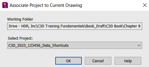
Figure 14.1 – Associating the current drawing with the project
After our Civil 3D Data Shortcuts project has been associated with our current file, we can then safely create data references as needed later on down the road.
Then, with our Site Plan Sheet.dwg file set up for us to include all objects necessary to represent and reference the existing and proposed built environment, we should have a plan view that looks similar to that shown in Figure 14.2.

Figure 14.2 – Site Plan Sheets.dwg file
With our Site Plan Sheets.dwg file configured, let’s go ahead and explore ways we can leverage Civil 3D’s tools to automate the way we create or generate our sheets and overall construction drawing set.
Technical requirements
The exercise files for this chapter are available at https://packt.link/UoiPn
Automating Plan Sheet creation
With our Site Plan Sheets.dwg file currently open, let’s begin familiarizing ourselves with the Map Task Pane tools available to us within Civil 3D. The Map Task Pane tools create, manage, display and publish maps, and can be accessed from the Palettes pulldown in our Home ribbon and by selecting the Map Task Pane tools as shown in Figure 14.3.

Figure 14.3 – Activating Civil 3D’s Map Task Pane tools
Once activated, you’ll receive a prompt at the Command Line asking you whether you’d like the task pane On or Off, at which point we’ll select (or type) On and hit the Enter key on our keyboard.
Using the following steps, we’ll be able to automate the creation of our Plan sheets to be included in our construction drawing set (also displayed in Figure 14.4):
- When the Map Task Pane appears, let’s go ahead and select the Map Book tab.
- Next, we’ll select New in the top-left corner of our Map Book tab.
- Finally, we’ll select Map Book to create a new Map Book.

Figure 14.4 – Creating a new Map Book in our Map task pane
After running through those steps, the Create Map Book dialog box will then appear, where we’ll make the following selections (also displayed in Figure 14.5):
- Source: Model Space
- Sheet Template: Settings
- Tiling Scheme: By Area
- Naming Scheme: Grid Sequential
- Key: Layers
- Legend: None
- Sheet Set: Create New
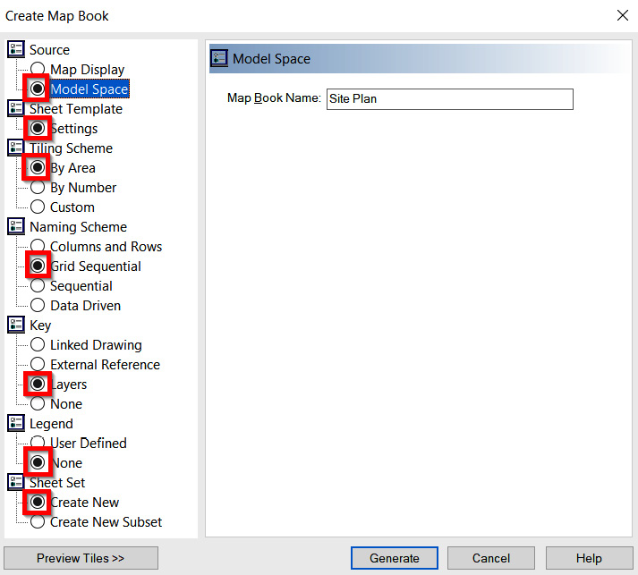
Figure 14.5 – Initial selections in Map Book
- Next, we’ll want to go a bit deeper into each of our selections to fill out available fields and options as follows:
- Source: Model Space
- Map Book Name: Site Plan
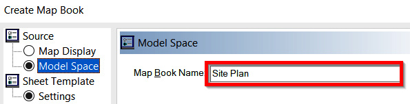
Figure 14.6 – Map Book > Source > Model Space Criteria
- Sheet Template: Settings (as shown in Figure 14.7):
- Choose a Sheet Template: C:UsersusernameAppDataRoamingAutodeskC3D 2023enuTemplateAutoCAD TemplateMap Book Template - 22x34 Classic.dwt
- Choose a Layout: Ansi D
- Include a Title block (name or file): Title Block
- Include Adjacent sheet links (name or file): Adjacent_Arrow_4
- Scale Factor: 20
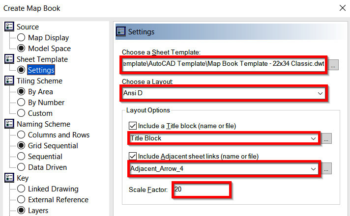
Figure 14.7 – Map Book > Sheet Template > Settings Criteria
- Tiling Scheme: By Area (as shown in Figure 14.8):
- Layer: Defpoints
- First corner: 1859517.48 and 1188684.05
- Opposite corner: 1861121.99 and 1190000.02
- % overlap of each tile: 0
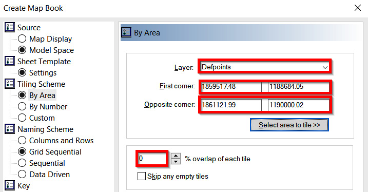
Figure 14.8 – Map Book > Tiling Scheme > By Area Criteria
Note
In lieu of plugging in coordinates for First corner and Opposite corner, we can alternatively use the Select area to tile >> button. When this has been activated, we’ll be able to draw a window around the extent of our project site and/or the area that we’d like to include in the automatic Plan Sheet creation process.
- Naming Scheme: Grid Sequential (as shown in Figure 14.9):
- Begin with: Rows
- Order from: Upper Left to Lower Right
- Start with: 1
- Increment by: 1
- Keep names for skipped tiles: Checked
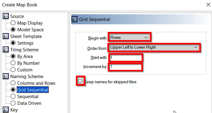
Figure 14.9 – Map Book > Naming Scheme > Grid Sequential Criteria
- Key: Layers (as shown in Figure 14.10). Select All Layers (easiest to use by pressing Shift) and click on the Add Layers for Map Key button.
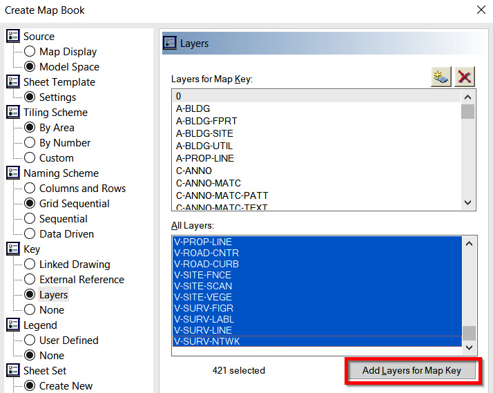
Figure 14.10 – Map Book > Key > Layers Criteria
- Legend: None (as shown in Figure 14.11):
- Sheet Set: Create New:
- In the path, select Practical Autodesk Civil 3D 2023Chapter 14Residential Subdivision.dst
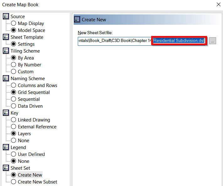
Figure 14.11 – Map Book > Sheet Set > Create New Criteria
- Finally, with all of our Map Book settings in place, let’s go ahead and click the Generate button at the bottom of the Create Map Book dialog box and watch the magic happen. Shortly after clicking on the Generate button, we’ll first notice that we now have a gridded layout displayed in Model Space covering our entire Residential Subdivision layout, as shown in Figure 14.12.
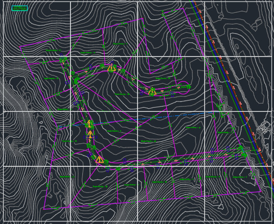
Figure 14.12 – Site Plan Sheets.dwg Model Space Gridded Layout
The second, and more important, item that we’ll notice is that along the bottom of our Civil 3D session, we now have 16 new Layouts created from the newly gridded layout of our design, as shown in Figure 14.13.
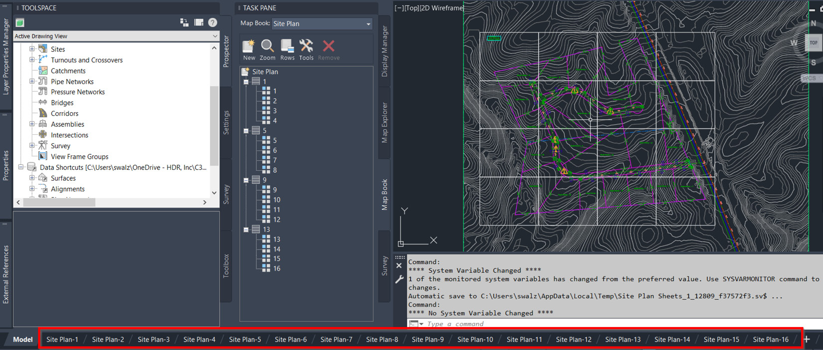
Figure 14.13 – Site Plan Sheets.dwg Layout tabs
As we flip through and activate each of our Layout tabs, we’ll see how easy Civil 3D’s Map Books can be at automating our first run at Plan Sheet generation. If, for whatever reason, we need to revisit our layout, we can always go back to our Map Book in Map Task Pane, right-click with our mouse on Site Plan Map Book, and select the Edit Settings and Rebuild… option, as shown in Figure 14.14.
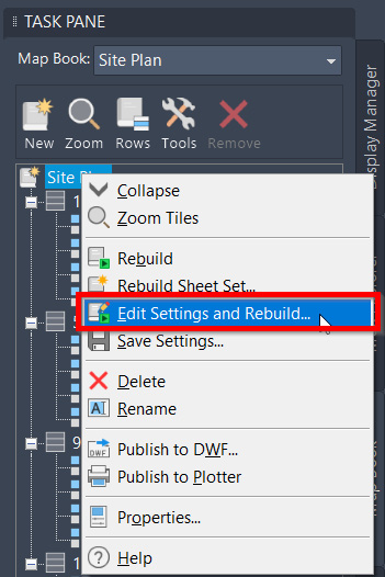
Figure 14.14 – Edit Settings and Rebuild…
Now that we’re satisfied with the Site Plan layouts to be included in our overall construction drawing set, we can use similar processes and tactics to generate additional plan-only sheets that have the potential to display Grading Plans, Erosion Control Plans, Utility Plans, and so on.
Automating Plan and Profile Sheet creation
Once we’ve gone ahead and created all plan-only Layouts and Sheets to be included in our construction drawing set, we can take the next step in automating the generation of our Plan and Profile Sheets. To automate the creation of these types of sheets, we’ll want to take a slightly different approach.
To get started, let’s go ahead and open up our Utility Model.dwg file located in Practical Autodesk Civil 3D 2023Chapter 14Model. The reason we’re starting with this Utility Model.dwg file instead of creating a new file to begin our Plan and Profile sheet creation is due to the fact that Civil 3D’s Plan Production Tools require a file that contains all anticipated modeled geometry that we’d like to include in our Plan and Profile sheets to be present in the current drawing.
Additionally, the automatic sheet creation process in using the Plan Production tools will automatically create a new drawing file for each Plan and Profile sheet we are attempting to generate.
Once we have opened the Utility Model.dwg file, let’s navigate up to our ribbons along the top, select the Output ribbon, and then select the Create View Frames tool within the Plan Production Panel, as shown in Figure 14.15.
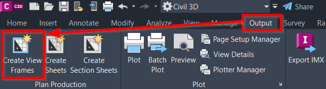
Figure 14.15 – Activating the Create View Frames tool
Once the Create View Frames tool has been activated, the Create View Frames dialog box will appear. You’ll notice that there are several tabs, or selections, that require input along the left-hand side of the Create View Frames dialog box.
Running through them, from top to bottom, we’ll fill out fields and makes selections as follows:
- Alignment (as displayed in Figure 14.16):

Figure 14.16 – Create View Frames dialog box – the Alignment tab
- Sheets (as displayed in Figure 14.17):
- Sheet Settings: Plan and Profile
- Template for Plan and Profile Sheet: C:UsersusernameAppDataRoamingAutodeskC3D 2023enuTemplatePlan ProductionCivil 3D (Imperial) Plan and Profile.dwt|ANSI D Plan and Profile 40 Scale
- View Frame Placement: Along Alignment
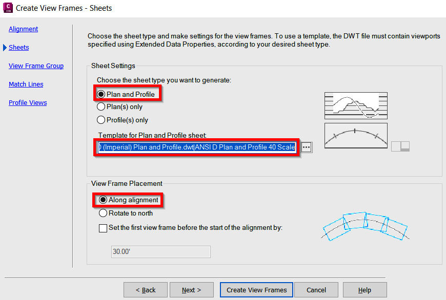
Figure 14.17 – Create View Frames dialog box – the Sheets tab
- View Frame Group (as displayed in Figure 14.18):
- Name: Plan and Profile - Subdivision Main Road - Access
- Description: Plan and Profile View Frames displayed along Subdivision Main Road - Access Alignment
- Layer: C-ANNO-VFRM
- Name: VF - (<[Next Counter(CP)]>)
- Style: Basic
- Label style: Basic
- Label location: Top left
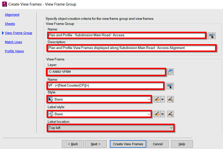
Figure 14.18 – Create View Frames dialog box – the View Frame Group tab
- Match Lines (as displayed in Figure 14.19):
- Snap station value down to the nearest: Check the box and set Station Value to 50
- Layer: C-ANNO-MTCH
- Name: ML - (<[Next Counter(CP)]>)
- Style: Basic
- Left label style: Basic Left
- Right label style: Basic Right
- Left label location: End
- Right label location: Start
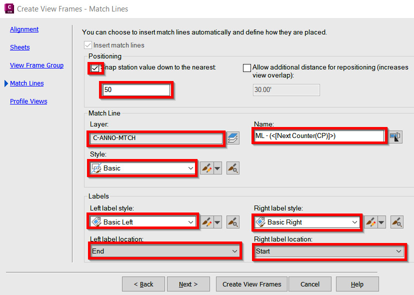
Figure 14.19 – Create View Frames dialog box – the Match Lines tab
- Profile Views (as displayed in Figure 14.20):
- Select profile view style: Profile View
- Select band set style: Plan Profile Sheets - Elevations and Stations
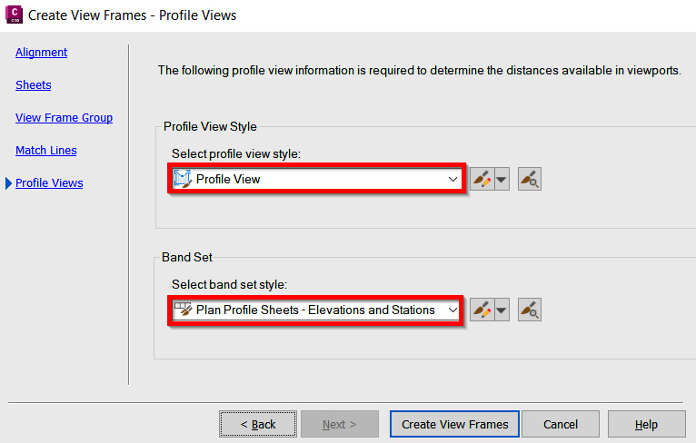
Figure 14.20 – Create View Frames dialog box – the Profile Views tab
After filling out all fields and making the selections as detailed, let’s go ahead and click on the Create View Frames button at the bottom of the Create View Frames dialog box. We should now be seeing two View Frames appear in our Model Space on top of our Residential Subdivision design, similar to that displayed in Figure 14.21.

Figure 14.21 – View Frames added to Model Space along our ALG - Subdivision Main Road -Access Alignment
Now, with our View Frames in place along ALG - Subdivision Main Road - Access Alignment, we’ll want to take the next step in automating our sheet creation of these areas. That said, let’s jump back up to our Output ribbon and select the Create Sheets tool, as shown in Figure 14.22.
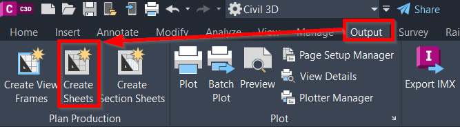
Figure 14.22 – Activating the Create Sheets tool
Once the Create Sheets tool has been activated, the Create Sheets dialog box will appear. Similar to the Create View Frames dialog box, you’ll notice that there are several tabs, or selections, that require input along the left-hand side of the Create Sheets dialog box. Running through them, from top to bottom, we’ll fill out fields and make selections as follows:
- View Frame Group and Layouts (as displayed in Figure 14.23):
- View Frame Group: Plan and Profile - Subdivision Main Road - Access
- View frame range: All
- Layout Creation: All layouts in one new drawing
- Layout Name: Plan and Profile - Subdivision Main Road - Access
- Choose the north arrow block to align in layouts: North
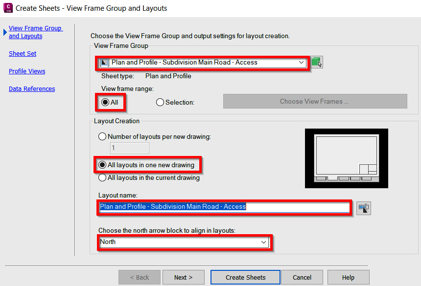
Figure 14.23 – Create Sheets dialog box – View Frame Group and Layouts
- Sheet Set (as displayed in Figure 14.24):

Figure 14.24 – Create Sheets dialog box – Sheet Set
- Profile Views (as displayed in Figure 14.25):
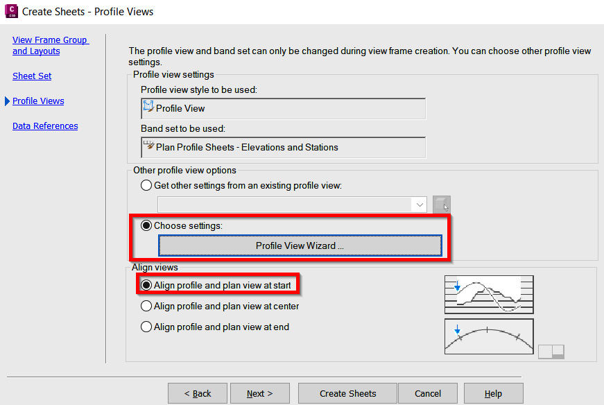
Figure 14.25 – Create Sheets dialog box – Profile Views
- Data References (as displayed in Figure 14.26):
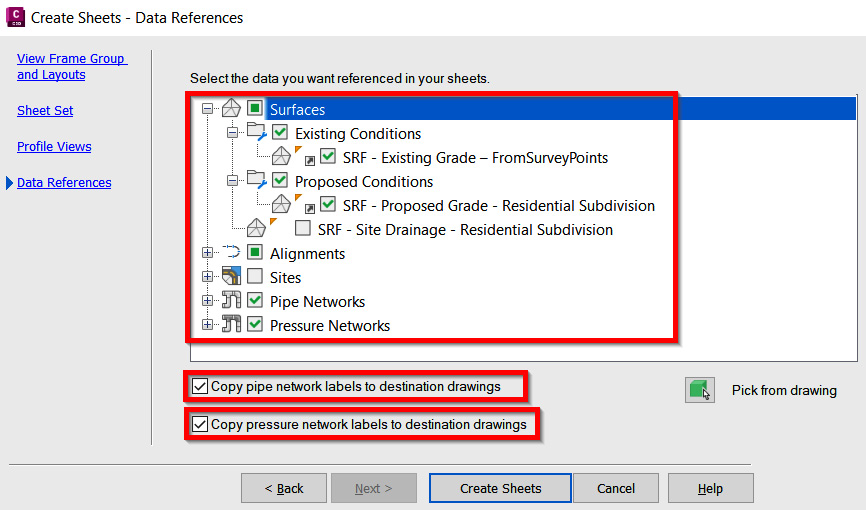
Figure 14.26 – Create Sheets dialog box – Date References
- With all of our Create Sheets settings defined, let’s go ahead and click on the Create Sheets button at the bottom of the Create Sheets dialog box. After clicking Create Sheets, we’ll be prompted to select Profile View Origin at the Command Line.
- Go ahead and click in a blank area in our Model Space to place the new Profile Views. After defining the location, we can now sit back and watch the magic happen where Civil 3D will automatically create our sheets and add them to our SHEET SET MANAGER list (as shown in Figure 14.27).
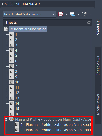
Figure 14.27 – Updated Sheet Set Manager
With our first run-through of automating the creation of our Plan and Profile sheets under our belt, let’s go ahead and run through similar processes to be applied to our ALG - Subdivision Side Road - Cul-De-Sac Alignment. A lot of the same fields and selections will be similar in both our Create View Frame and Create Sheets dialog boxes. We’ll quickly realize that due to the scale (1” = 40’) being applied and the short length of our ALG – Subdivision Side Road – Cul-De-Sac Alignment, only one sheet will actually be created.
In any event, this practice and workflow are still advisable to drive consistency, leverage automation as much as possible, and keep all newly created Sheets available in our Sheet Set Manager. After running through the process Plan and Profile Sheet Creation process again, let’s jump over to our Section Sheets to gain some insight as to how we can continue to leverage automated sheet generation workflows.
Automating Cross Section Sheet Creation
Now that we have created our plan-only and Plan and Profile Sheets using the various automated methods available to us within Civil 3D, let’s go ahead and place our Cross Sections into Sheets using automated workflows as well. To automate the creation of these types of sheets, we’ll (yet again) want to take a slightly different approach.
That said, let’s start by opening up our Section Reference.dwg file located in Practical Autodesk Civil 3D 2023Chapter 14Reference. After opening, we’ll want to immediately use Save As on Section Sheets.dwg, and place it in our Practical Autodesk Civil 3D 2023Chapter 14Sheet location. Using Save As allows us to take what we’ve already developed in this file and save it as a Sheet File for our automated Section sheet generation.
Note
Later on, we’ll end up deleting all contents from Model Space in our newly created Sheet File and replacing it by externally referencing in our Section Reference.dwg. Speaking from experience, although this workflow sounds a little backward, it’s actually the most foolproof process we have available to us at present time with Civil 3D.
With our new Section Sheets.dwg file created and currently open, let’s navigate back up to our Output ribbon along the top of our Civil 3D session, and select the Create Section Sheets Tool within our Plan Production Panel, as shown in Figure 14.28.
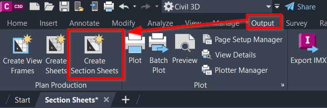
Figure 14.28 – Activating the Create Section Sheets tool
When the Create Section Sheets tool has been activated, the Create Section Sheets dialog box will appear, where we’ll use the following steps to fill out the fields and make necessary selections and generate our Cross Section Sheets (also displayed in Figure 14.29):
- Select alignment: ALG - Subdivision Main Road - Access
- Sample line group name: SLG - Subdivision Main Road - Access
- Select section view group: Section View Group - 1
- Layout name: Cross Sections - (<[Next Counter(CP)]>)
- Sheet Set: Select the Add to existing sheet set option, click on the ellipsis, navigate to Practical Autodesk Civil 3D 2023Chapter 14, and select Residential Subdivision.
- Select the Create Sheets button.
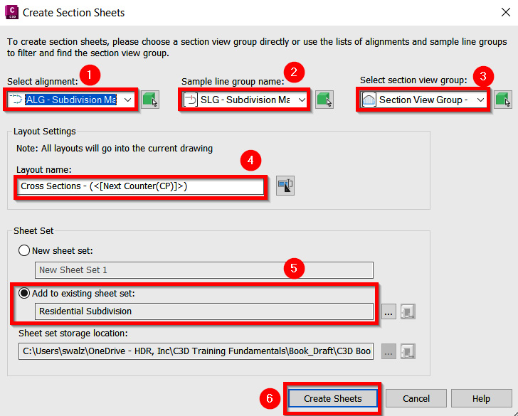
Figure 14.29 – Activating the Create Section Sheets tool
After selecting the Create Sheets button in our Create Section Sheets dialog box, we can sit back (again) and watch (more of) the magic happen where Civil 3D will automatically create our sheets and add them to our SHEET SET MANAGER list (as shown in Figure 14.30).
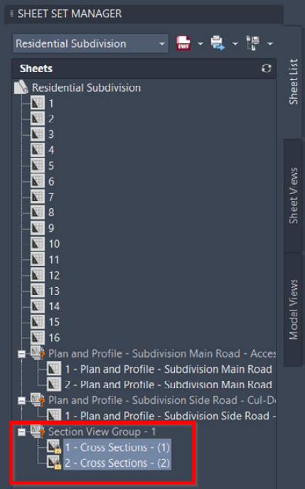
Figure 14.30 – Updated Sheet Set Manager
We’ll also notice that we now have two new Layouts created along the bottom of our drawing (refer to Figure 14.31), which are our official Cross Section sheets that will be included in our overall construction drawing set for submission.
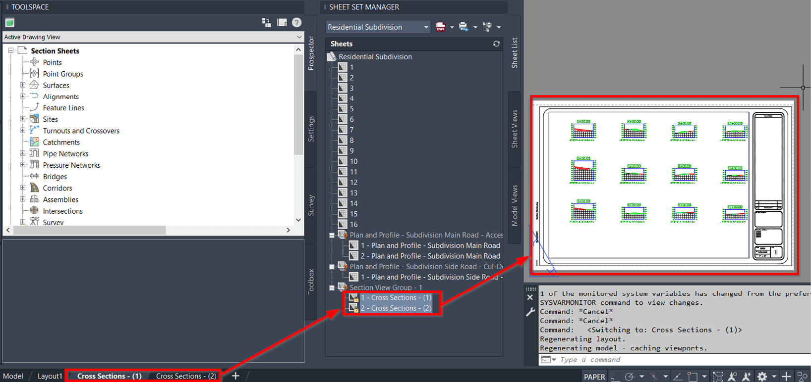
Figure 14.31 – New Layouts added to Cross Section Sheets.dwg
With our first run-through of automating the creation of our Cross Section Sheets under our belt, let’s go ahead and run through similar processes to be applied to our ALG - Subdivision Side Road - Cul-De-Sac Alignment. A lot of the same fields and selections will be similar in both our Create Section Sheets dialog boxes.
As was the case with our Plan and Profile Sheet creation process, we’ll notice that due to the shorter length of our ALG - Subdivision Side Road - Cul-De-Sac Alignment, only one sheet will actually be created.
After all the Cross Section Sheets have been created, we can then safely go back into Model Space and replace the existing content with that of our Section Reference.dwg file located in Practical Autodesk Civil 3D 2023Chapter 14Reference.
To do so, we’ll take the following steps:
- Select All objects (Ctrl + A).
- Delete/erase all selected objects.
- Enter the XREF command.
- Attach the Section Reference.dwg file located in Practical Autodesk Civil 3D 2023Chapter 14Reference as an Overlay.
Now, with all Sheet Files showing Plan only, Plan and Profile, and Sections, we’ve been able to shore up most of our construction drawing set. Obviously, this doesn’t necessarily complete our construction drawing set as we still need to pull together our Cover, General, and Detail sheets, but following these workflows will essentially get you close to 80% of the way there.
Summary
As we worked through this chapter, we experienced firsthand how the proper configuration and linking the modeled objects included in our design will allow us to leverage automation in the end.
With Civil 3D’s ability to dynamically link and associate a multitude of model objects together, we are essentially eliminating necessary rework and the risk of going over budget and schedule, as we have historically grown accustomed to.
Throughout this chapter, we’ve reviewed the Plan Production capabilities and tools available to us within Civil 3D, where we can automatically generate sheet files of our design, leading to a seamless approach to submitting our design as part of the Digital Delivery process. As we’ve witnessed in the past, the sheeting process has begun much earlier on in the design process, typically just before a Conceptual Design review.
However, as the modeling process becomes more intricate, and technology advancements continue to increase the possibilities of reviewing our models in place of sheets, we must spend more time and effort upfront ensuring that our models are truly representative of our design and that we are maintaining dynamic linking between as many modeled objects as possible to minimize risk and rework later on down the road.
This chapter marks the end of this introductory guide for Civil 3D for infrastructure analysis and design. We have traversed every aspect of Civil 3D from grading and corridor modeling to pipe networks and production plan layouts. Civil 3D is a powerful tool that can make your civil designs not only easier to generate but also more intelligent and dynamic as projects evolve.
This guide is a practical walk-through of the real-world tools you will use every day for active team projects. As you wrap up these exercises, you should have foundational skills to leverage far into your design career. Civil 3D has many more tools, integrations, and tricks for carrying your work into construction, coordination, and even further after the design has been finalized. Use this guide as a tool to plant your feet in the civil software design world and look for more resources to take you to the next level.