
9
Land Development Tool Belt for Everyday Use
In Part 1, Getting Acquainted with Civil 3D and Starting Your Next Project Up for Success, we gained some insight and understanding of how Civil 3D operates as we discussed many of the foundational settings, configurations, and workflows necessary to begin a design project within the Civil 3D environment.
In Part 2, Designing and Modeling with Civil 3D from Start to Finish, we learned how properly setting up a survey model from the get-go is critical to running a smooth design. We’ve also gained some insight into how surfaces, alignments, and profiles are all tied to each other dynamically and are the core ideas required to progress into our residential subdivision design moving forward.
In this chapter, we’ll continue to progress through our residential subdivision design while also gaining additional insight and understanding of which other tools are available inside of Civil 3D and how we can leverage all while maintaining a dynamic link between these objects.
We’ll also begin to see firsthand how maintaining dynamic linking between all modeled objects in our design will save us many steps and unnecessary time later on down the road in the event that we need to pivot and make some adjustments in our design due to various unforeseen circumstances.
Furthermore, we’ll begin unwrapping our major land development tools that are available to us within Civil 3D. These tools will allow us to continue building on top of our foundational objects and take the next step in modeling a residential subdivision design layout. That said, in this chapter, we’ll be covering the following topics:
- Creating and managing parcels
- Creating and managing sites
- Leveraging grading tools for our site design
With that, let’s go ahead and open up Civil 3D, or go to your start screen if already open, and create a new drawing using similar steps outlined in Chapter 7, Alignments - The Second Foundational Component to Designs within Civil 3D. We can use our Company Template File.dwt file located in Practical Autodesk Civil 3D 2024Chapter 9 and select Open in the lower right-hand corner of the Select Template dialog box. Once our new file is created, we’ll want to save it as our Site Plan Reference.dwg file to our Practical Autodesk Civil 3D 2024Chapter 9Reference location.
As discussed back in Chapter 3, Sharing Data within Civil 3D, reference files are intended to contain/represent 2D geometry and static elements and annotation. Reference files would include content such as surveyed planimetrics, civil site plan geometry, erosion control BMPs, and so on.
Although parcels are considered Civil 3D objects, they are not able to be data referenced across multiple files. When we get to the sections covering sites and grading tools, we’ll want to jump back into our Grading Model.dwg file to continue progressing the modeled design objects that will require further coordination via data referencing.
With that, let’s go ahead and attach our Survey Model.dwg file as an overlay, contained within our Practical Autodesk Civil 3D 2024Chapter 9Model location. Then, we’ll want to jump back into our Prospector tab in our Toolspace, and then set the working folder of our data shortcuts project to the Practical Autodesk Civil 3D 2024Chapter 9 location and select the C3D_2024_123456_Data_Shortcuts project, as shown in Figure 9.1:
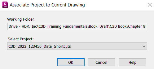
Figure 9.1 – Associate Project to Current Drawing dialog
After our Civil 3D data shortcuts project has been associated with our current file, we can then safely create data references of ALG - Subdivision Main Road - Access and ALG - Subdivision Side Road - Cul-De-Sac alignments into our current Site Plan Reference.dwg file.
To do this, we need to expand our Alignments category and our Proposed Conditions folder, right-click on each object (shown in Figure 9.2) and select the Create Reference option for each:
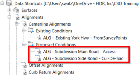
Figure 9.2 – Creating data references of identified Civil 3D objects
Then, with our Site Plan Reference.dwg file set up for us to include all objects we have available to us to represent and reference the existing environment, along with a few objects of the future built environment, we are now ready to continue designing our residential subdivision layout.
Technical requirements
It’s important to note that Autodesk’s Civil 3D can oftentimes be very taxing on your computer. There is a lot of processing that goes on with modeled design elements, even in the background, that enables the dynamic (connected) capabilities to occur throughout the Building Information Modeling (BIM) design lifecycle.
In turn, many technical requirements need to be considered to allow Autodesk’s Civil 3D to operate at its full potential. We’ll review the minimum requirements that Autodesk recommends, with a few of my suggestions added to increase efficiency and speed throughout the BIM design process:
- Operating system: 64-bit Microsoft Windows 10
- Processor: 3+ GHz
- Memory: 16 GB RAM (I suggest going with either 64 GB or 128 GB)
- Graphics card: 4 GB (I suggest going with 8+ GB)
- Display resolution: 1980 x 1080 with True Color
- Disk space: 16 GB
- Pointing device: MS Mouse compliant
The exercise files for this chapter are available at https://packt.link/UoiPn
Creating and managing parcels
In this section, we’ll begin to explore and understand how to utilize the parcel tools available to us within Civil 3D to support our residential subdivision design. We’ll begin by creating our overall parcel object that will combine the two existing parcels from our survey.
Using the NCOPY command (type this at the command line), we’ll go ahead and copy our linework showing only the outermost parcel boundary from our Survey Model.dwg external reference into our Site Plan Reference.dwg file, as shown in Figure 9.3:
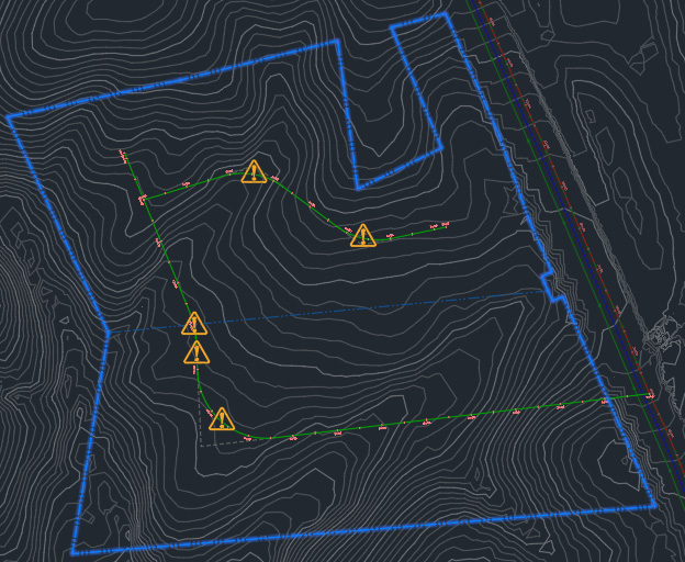
Figure 9.3 – NCOPY outermost parcel linework
Once this linework has been extracted from our Survey Model.dwg file and placed into our Site Plan Reference.dwg file, we’ll then want to isolate these objects and use the JOIN command (type this at the command line) to create one continuous polyline of the outermost parcel linework.
The next step we’ll want to take is to convert this linework to a parcel object. To access our parcel creation tools, we’ll want to activate our Home ribbon along the top of our Civil 3D session, go to our Create Design panel, and click on the down arrow next to where it says Parcel (refer to Figure 9.4):

Figure 9.4 – Parcel tools
Let’s go ahead and select the Create Parcel from Objects tool and select the new linework we just extracted from our Survey Model.dwg file. Once selected, hit the Enter key and we’ll then be prompted with a Create Parcels - From objects dialog box, as shown in Figure 9.5:
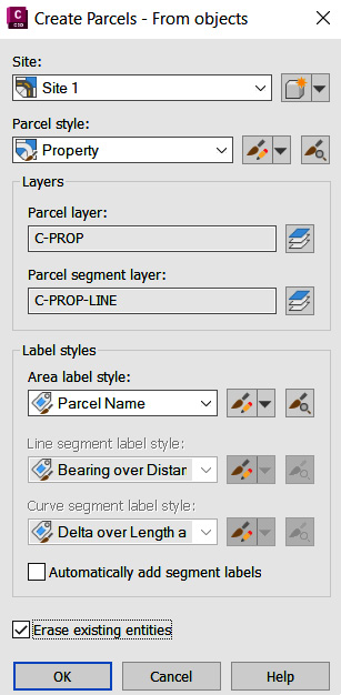
Figure 9.5 – Create Parcels From objects dialog box
In our Site field, we’ll want to go ahead and create a new site by selecting the down arrow to the right of the icon next to the field and selecting the Create New option (refer to Figure 9.6):
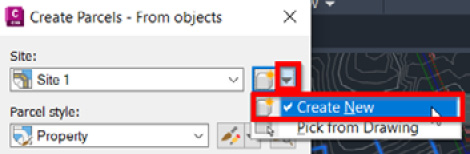
Figure 9.6 – Creating a new site
Once selected, we’ll fill out the following fields, also shown in Figure 9.7, and then hit the OK button in the lower right-hand corner of the New Site Creation dialog box:
- Name: SIT - Proposed – Overall
- Description: Overall Residential Subdivison Boundary
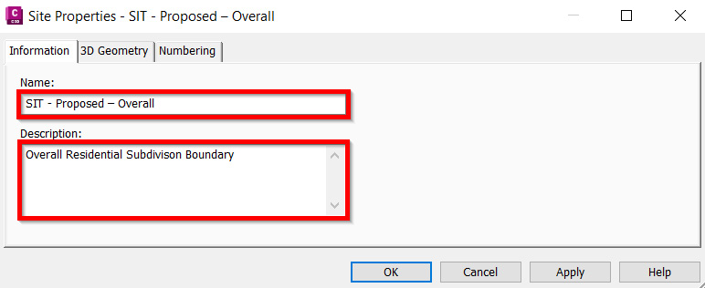
Figure 9.7 – New Site Creation dialog box
We’ll then make the following selection in our Create Parcels From objects dialog box, also shown in Figure 9.8, and then click on the OK button:
- Site: SIT - Proposed – Overall
- Parcel style: Property
- Area label style: Name Area & Perimeter
- Line segment label style: Bearing over Distance
- Curve segment label style: Delta over Length and Radius
- Automatically add segment labels: Check
- Erase existing entities: Check

Figure 9.8 – Create Parcels From Objects dialog box
Next, we’ll want to create a right of way within our newly created parcel that follows our data-referenced ALG - Subdivision Main Road - Access and ALG - Subdivision Side Road - Cul-De-Sac alignments. Before creating our right of way, though, we’ll need to make a slight adjustment and move our data-referenced alignments into our newly created SIT - Proposed – Overall site.
To do so, we’ll select both data-referenced ALG - Subdivision Main Road - Access and ALG - Subdivision Side Road - Cul-De-Sac alignments, right-click on our mouse, and select the Move to Site… option, as shown in Figure 9.9:
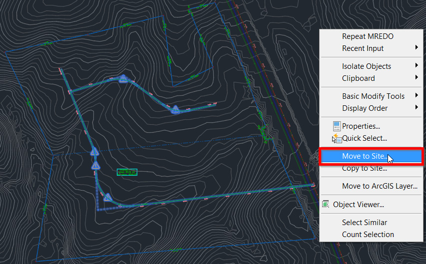
Figure 9.9 – Moving alignments to the site
When our Move to Site dialog box appears, we’ll select the Destination site type as SIT - Proposed – Overall, check the Alignments boxes, and then click on the OK button, as shown in Figure 9.10:
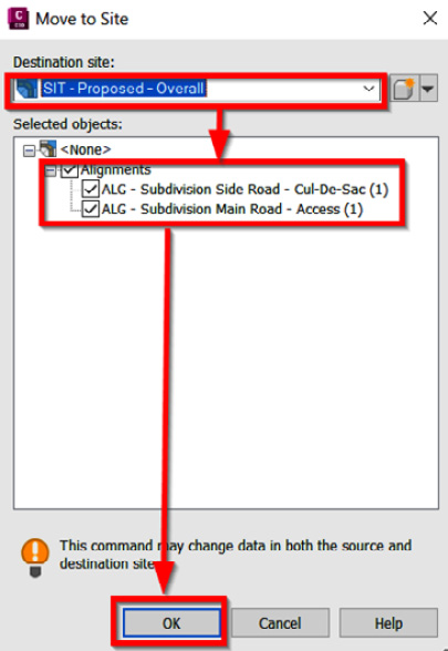
Figure 9.10 – Move to Site dialog box
Now, going back up to our parcel creation tools in our Home ribbon, we’ll select the Create Right of Way tool. When prompted to select our parcel, we’ll need to select our Parcel label in the center of our newly created parcel, instead of the outermost boundary linework, and hit Enter to accept our selection.
After hitting the Enter button on our keyboard, a Create Right of Way dialog box will appear, where we’ll accept the default values and selections, as shown in Figure 9.11:
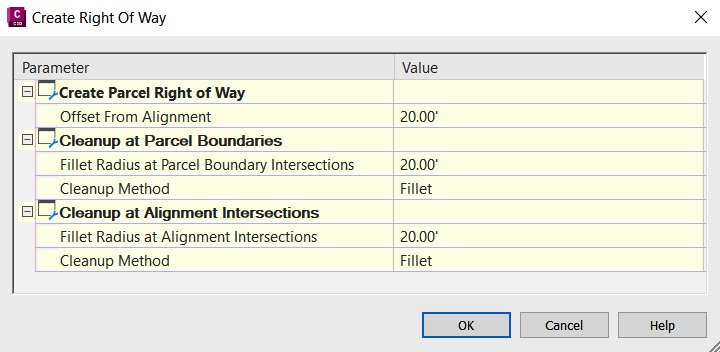
Figure 9.11 – Create Right of Way dialog box
After clicking on the OK button in our Create Right of Way dialog box, our proposed parcel layout should look similar to that shown in Figure 9.12:

Figure 9.12 – Site plan reference model after right-of-way creation
With our outer parcel boundary and our right-of-way parcel created, we can now use the parcel creation tools to lay out our individual lots within our residential subdivision design. Going back up to our Home ribbon, then to the Parcel dropdown, let’s now select the Parcel Creation Tools option, at which point our Parcel Layout Tools toolbar will appear:
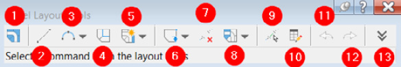
Figure 9.13 – Parcel Layout Tools toolbar
Running through the tools as numbered in Figure 9.13, we have the following:
- Create Parcel: Allows us to create parcels based on criteria defined within item 13, Expand the Toolbar
- Add Fixed Line – Two Points: Allows us to manually create a fixed parcel line based on two points
- Add Fixed Curve: Allows us to manually create a fixed curve based on either two or three points
- Draw Tangent – Tangent with no Curves: Allows us to manually create tangents
- Line Tools: Allows us to either create or edit parcel lines
- Point of Intersection Tools: Allows us to add, remove, and/or break apart points of intersection (PIs)
- Delete Sub-Entity Tools: Allows us to delete sub-entities based on manual selection
- Parcel Union Tools: Allows us to join multiple parcels
- Pick Sub-Entity: Allows us to select a parcel sub-entity and display its parameters
- Sub-Entity Editor: Allows us to display parameters of identified sub-entities
- Undo: Allows us to undo the previous command(s)
- Redo: Allows us to reapply or redo commands that were undone
- Expand the Toolbar: Allows us to define criteria for item 1, Create Parcel
Now that we have a high-level understanding of which parcel creation tools we have available to us, let’s start putting some of them to practice. Before getting started, though, we’ll need to look up our local town/city/county/state zoning codes to be able to fill in our parcel criteria.
An example of the parcel criteria we’ll be using for this particular exercise can be found at https://www.yorkcounty.gov/DocumentCenter/View/82/Zoning-Ordinance-Summary-Table-PDF?bidId=. Once your project’s location is determined, we can then go ahead and use the Expand the Toolbar option within our Parcel Layout Tools toolbar to define our criteria for parcel generation, also shown in Figure 9.14:
- Minimum Area: 33000.00 Sq. Ft.
- Minimum Frontage: 50.00'
- Use Minimum Frontage At Offset: Yes
- Frontage Offset: 15.00'
- Minimum Width: 130.00'
- Minimum Depth: 30.00'
- Use Maximum Depth: No
- Maximum Depth: 500.00'
- Multiple Solution Preference: Use shortest frontage
- Automatic Mode: On
- Remainder Distribution: Redistribute remainder
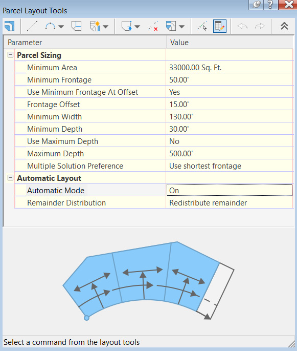
Figure 9.14 – Parcel layout criteria
After filling out our parcel criteria, we’ll then select the down arrow next to our Line tool icon (listed as number 5 in Figure 9.13) and select the Slide Line Create tool to begin our automatic parcel generation throughout our residential subdivision site. Once the Slide Line Create tool has been selected, a Create Parcels Layout dialog box will appear, at which point we’ll want to make the following selections (also shown in Figure 9.15):
- Site: SIT - Proposed – Overall
- Parcel style: Single-Family
- Area label style: Parcel Name
- Line segment label style: Bearing over Distance
- Curve segment label style: Delta over Length and Radius
- Automatically add segment labels: Check
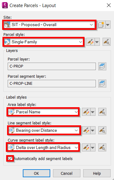
Figure 9.15 – Create Parcels Layout dialog box
After our fields have been filled and we select the OK button within the Create Parcels Layout dialog box, we’ll want to bring our attention down to the command line and follow the steps listed out here:
- First, we’ll be prompted to select the starting point on the frontage, which refers to our street right-of-way frontage. Let’s go ahead and snap to the endpoint of our right-of-way parcel, on the north side, closest to York Highway, as shown in Figure 9.16:
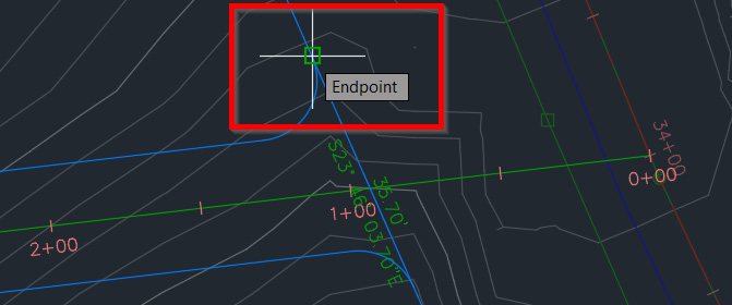
Figure 9.16 – Snapping to the endpoint of our right-of-way parcel
- After snapping to the northern endpoint of our right-of-way parcel shown in Figure 9.16, we’ll then be prompted at our command line to select the endpoint of our frontage, which will be our southern endpoint.
Before snapping directly to the southern endpoint, we’ll need to drag our mouse from right to left along the entire length of our right-of-way parcel to ensure that we are defining the full path, which will be recognized as street frontage in our automatic parcel creation process, as shown in Figure 9.17:
Figure 9.17 – Defining path of street frontage
- Once our path has been highlighted as shown in Figure 9.17, we’ll then want to snap to the endpoint of our right-of-way parcel, this time on the south side, closest to York Highway, as shown in Figure 9.18:
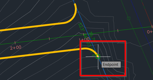
Figure 9.18 – Snapping to the endpoint of our right-of-way parcel
- After snapping to the endpoint on the southern side, we’ll then be prompted to specify the angle in our command line. For this prompt, we’ll just hit the Enter key on our keyboard to bypass and accept the default.
- After hitting the Enter key, Civil 3D will run through the process of automatically laying out our Single-Family parcels throughout our residential subdivision design, as shown in Figure 9.19:
Figure 9.19 – Automatic parcel layout
- Finally, we’ll then be asked in our command line if we’d like to accept the results, at which point we’ll type YES and hit the Enter key to finish the automatic parcel layout process, with the final result appearing similar to that shown in Figure 9.20:

Figure 9.20 – Automatic parcel layout results
Congratulations! We have now created our Single-Family parcels, leveraging automated workflows within Civil 3D, to lay out our residential subdivision design. If adjustments need to be made to our parcel layout thereafter, we’d want to pull up our Parcel Layout Tools toolbar again, go back to our Line Tools dropdown (identified as number 5 in Figure 9.13), and select the Single Line – Edit tool to adjust our parcel lines accordingly.
Creating and managing sites
As we were creating parcels in the previous section, you may have noticed that during the parcel creation process we had to associate our parcels with a site, and we ended up creating a site called SIT - Proposed – Overall. In this section, we’ll dive a bit deeper to explore and understand how to continue leveraging and incorporating sites into our residential subdivision design.
With that, let’s go ahead and open up our Grading Model.dwg file located within our Practical Autodesk Civil 3D 2024Chapter 9Model location. Once opened, you’ll notice that I’ve already prepped the file to contain polylines representing our Single-Family parcel boundary lines created in the previous section, along with building setback lines offset 20' from each lot boundary.
Using the following basic AutoCAD commands, I was able to convert our Single-Family parcel boundaries to polylines and carry them into our Grading Model.dwg file:
- Begin by saving the Site Plan Reference.dwg file.
- In our Site Plan Reference.dwg file, we’ll isolate parcels (including Single-Family and Right-of-Way parcels).
- Window select all parcels after isolation.
- Type explode in the command line to explode parcels.
- Type flatten into the command line to flatten parcels (to ensure that all linework is at elevation 0).
- Leverage the BPOLY command (type this at the command line) to create polyline boundaries for each individual parcel.
- Select the new polylines that we just created.
- Right-click on the mouse and select the Clipboard | Copy with Base Point option.
- Type in 0,0,0 as the base point coordinates at the command line.
- Jump into our Grading Model.dwg file, right-click, and select the Clipboard | Paste option.
- Type in 0,0,0 as the base point coordinates at the command line.
- Offset boundary lines internal to each lot by 20 feet, except for our Open Space lot (shown hatched in Figure 9.21).
- The final appearance should look similar to that shown in Figure 9.21:
Figure 9.21 – Grading Model.dwg file after polylines representing parcels are copied and pasted
Bringing our attention back to the Toolspace, we’ll want to select the Prospector tab, navigate to our sites (as shown in Figure 9.22), right-click on Sites, and select New:
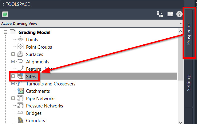
Figure 9.22 – Accessing Sites in Toolspace | Prospector tab
After selecting New, a Site Properties dialog box will appear, at which point we’ll fill out the following fields accordingly (also shown in Figure 9.23), and then click the OK button in the lower right-hand corner of the dialog box:
- Name: SIT - Proposed – Building Pads
- Description: Buildings Pad Grading
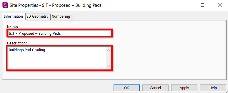
Figure 9.23 – Site Properties dialog box
It’s important to note that sites by themselves are managed directly in the drawing file they are created within, with a few exceptions. If we go back to our Toolspace, select the Prospector tab, and expand our Sites category and newly created SIT - Proposed – Building Pads site, we can see we have a few types of Civil 3D objects that are able to be associated with each individual site created.
As shown in Figure 9.24, we have the following Civil 3D objects able to be associated with sites: Alignments, Feature Lines, Grading Groups, and Parcels:
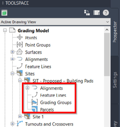
Figure 9.24 – Civil 3D objects associated with each site
Note
Alignments are the only object in Civil 3D 2024 that can be data referenced into other files from within our sites. When data referencing alignments that are associated with sites into other drawing files, they will automatically create the site that they are associated with, and the alignments will be contained within.
Sites alone do not provide a ton of function, but Civil 3D objects contained within add tremendous value to our designs. That said, sites add another level of Civil 3D object management that allows us to reference objects from other sites as needed.
As an example, if we were to create feature lines in one site, we would be able to set our grading groups that utilize those feature lines to target or reference components in other sites. This concept will become a little clearer as we progress throughout the next sections and chapters.
Leveraging grading tools for our site design
Now that our new SIT - Proposed – Building Pads site has been created, we can now go ahead and start adding feature lines and grading objects to our site. In this section, we’ll learn how to leverage multiple feature lines and grading modeling tools to support a typical civil site design and analysis to further our residential subdivision design.
For starters, we’ll begin by converting our setback lines to feature lines that will ultimately be associated with our SIT - Proposed – Building Pads site. To convert our polylines representing the setback lines, we’ll go up to our Home ribbon and locate our feature line tools located within our Create Design panel.
Once located, we’ll click on the down arrow next to Feature Line to pull down the following list of feature line tools available to us (also shown in Figure 9.25):
- Create Feature Line: Allows us to manually create new feature lines by defining PIs and points of vertical intersection (PVIs)
- Create Feature Lines from Objects: Allows us to convert existing lines, arcs, polylines, and 3D polylines to feature lines
- Create Feature Lines from Alignment: Allows us to convert existing alignments to feature lines
- Create Feature Line from Corridor: Allows us to convert feature lines from existing corridor-modeled breaklines
- Create Feature Line from Stepped Offset: Allows us to create a feature line based on a defined horizontal and vertical offset from an identified feature line, survey figure, polyline, and/or 3D polyline
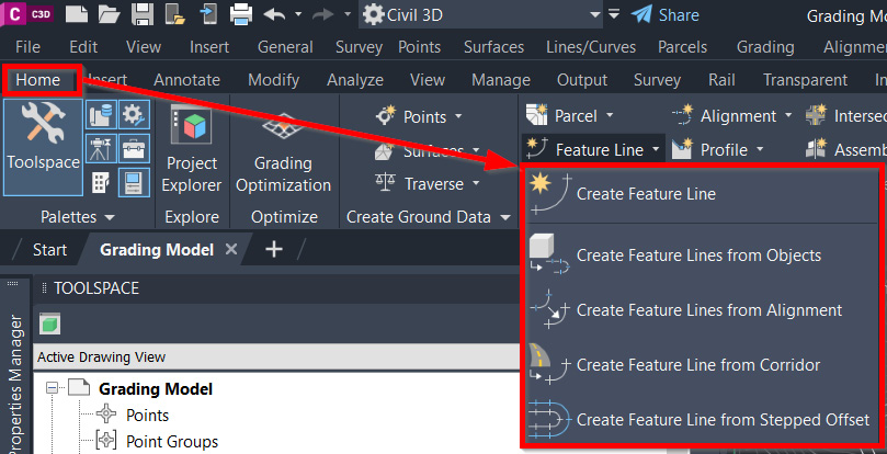
Figure 9.25 – Feature line tools
To actually convert our setback polylines to feature lines, we’ll want to select Create Feature Line from the Objects tool. Then, once the command has been initiated, we’ll go ahead and select all of our setback polylines, as shown in Figure 9.26:
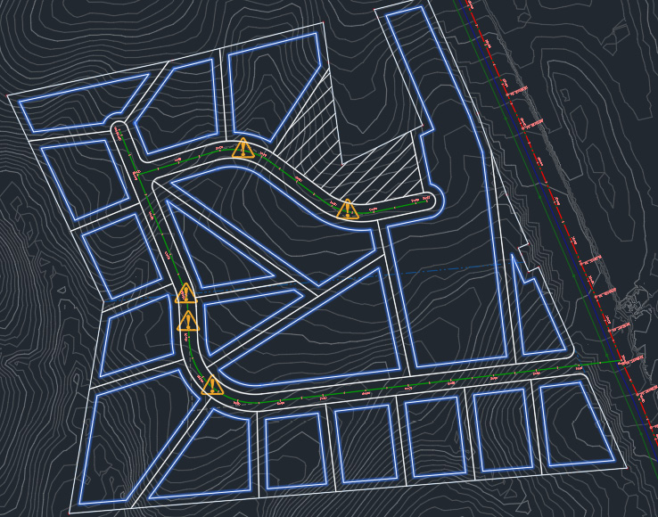
Figure 9.26 – Creating feature lines from an object: selection of setback polylines
After all polylines have been selected, we’ll simply hit the Enter key on our keyboard to accept our selection set, where we’ll then have a Create Feature Lines dialog box appear.
Let’s go ahead and fill out the following fields and make the following selections, as shown in Figure 9.27:
- Site: SIT - Proposed – Building Pads
- Style: Check the box and select the Platform Edge style
- Erase existing entities: Check
- Assign elevations: Check
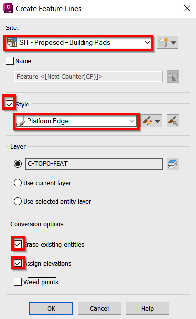
Figure 9.27 – Create Feature Lines dialog box
Since we had checked the box next to Assign elevations, we’ll then be prompted with an Assign Elevations dialog box after clicking the OK button in the lower portion of the Create Feature Lines dialog box.
In the Assign Elevations dialog box, we’ll want to select the option to assign elevations from our SRF Existing Grade – FromSurveyPoints surface model, and also check the box next to Insert intermediate grade break points, and then click the OK button in the lower portion of the Assign Elevations dialog box, shown in Figure 9.28:
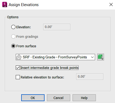
Figure 9.28 – Assign Elevations dialog box
Note
By checking the box next to Insert intermediate grade break points, we are adding PVIs along the perimeter of each of the polylines where they cross the triangulated irregular network (TIN) lines of our SRF - Existing Grade – FromSurveyPoints surface model. This will allow us to generate a very tight and accurate design surface model as we progress our residential subdivision layout.
With our feature lines created, we’ll now want to explore the grading tools that we have available to us within Civil 3D. Going back up to our Home ribbon and Create Design panel, let’s click the down arrow next to Grading to access our grading tools, as shown in Figure 9.29:
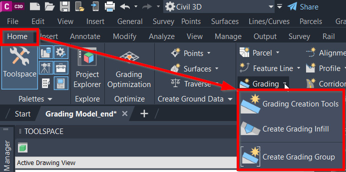
Figure 9.29 – Civil 3D grading tools dropdown
The key grading option we’ll want to focus on here is the first selection of Grading Creation Tools. The additional two options, Create Grading Infill and Create Grading Group are accessible with the Grading Creation Tools option as well.
After selecting the Grading Creation Tools option, the Grading Creation Tools toolbar will appear, as shown in Figure 9.30:

Figure 9.30 – Grading Creation Tools toolbar
Running through the tools as numbered in Figure 9.30, we have the following:
- Set the Grading Group: Allows us to select and/or create a grading group that our grading objects will be associated with
- Set the Target Surface: Allows us to select a surface in our current file that we will target for daylighting purposes
- Set the Grading Layer: Allows us to manually set the grading layer on which our grading objects will be placed
- Select a Criteria Set: Allows us to utilize a predefined grading criteria set
- Select a Grading Criteria: Allows us to specify which type of grading object we intend to create next
- Grading Criteria Manager: Allows us to create and modify grading criteria
- Grading Type Selection: Allows us to change the grading type from a predefined Grading Criteria selection to an Infill or Transition between two grading objects and slopes
- Grading Editing Tools: Allows us to modify grading objects
- Grading Volume Tools: Allows us to access grading volume tools
- Grading Editor: Allows us to edit grading objects
- Elevation Editor: Allows us to edit elevations of feature lines
- Grading Group Properties: Allows us to edit grading group properties
- Grading Properties: Allows us to edit properties associated with grading objects
- Expand the Toolbar: Allows us to define criteria as relates to grading methods, slope projection, and conflict resolution
Moving forward, we’ll want to create grading objects for each parcel so that we can establish a flat area inside of all of the setback lines. This flat area will essentially represent the building pads upon which our houses will be built. That said, we’ll want to take note of the approximate elevation on the street side within each of our setback feature lines and create grading objects to target those elevations.
To identify the approximate elevation, we’ll simply hover our mouse over a decent location for a second or so, at which point Civil 3D object references will list out next to our cursor, one of which will reference our SRF - Existing Grade – FromSurveyPoints surface model, along with the elevation that our cursor is hovering over (refer to Figure 9.31 for an example of what this may look like):
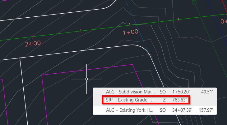
Figure 9.31 – Identifying the approximate elevation on the roadside of the setbacks
Using the following workflow and detailed steps for our southeastern parcel, we’ll begin applying grading objects and generating a proposed surface model using these setback feature lines:
- Let’s go ahead and change our grading criteria selection from Grade to Distance to Grade to Elevation by using the down arrow dropdown in our Select Grading Criteria box (listed as number 5 in Figure 9.30).
- Once changed to Grade to Elevation, we’ll then select our Grading Type Selection icon (listed as number 7 in Figure 9.30), to initiate the creation process.
- You will then be prompted to select a site that we want to associate our grading objects with. When the dialog box appears, we’ll want to select our SIT - Proposed – Building Pads site and select the OK button.
- Once the OK button has been selected, a Create Grading Group dialog box should appear. Let’s go ahead and fill out the following fields and make the following selections (also shown in Figure 9.32), and then click the OK button toward the bottom of the dialog box:
- Name: SGG - Proposed – Building Pads
- Description: Proposed Building Pads Grading Objects
- Automatic surface creation: Check
- Surface style: Contours 1’ and 5’ (Design)
- Tessellation spacing: 10.00'
- Tessellation angle: 3.0000 (d)
- Volume base surface: Check and select SRF - Existing Grade – FromSurveyPoints
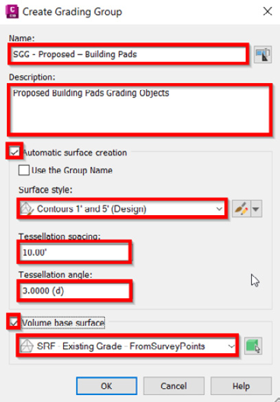
Figure 9.32 – Create Grading Group dialog box
- After selecting the OK button, we’ll be prompted with one more dialog box, this time being a Create Surface dialog box. In the Create Surface dialog box, we’ll want to give our new surface a name in close alignment with the grading group that it’s referencing. That said, let’s go ahead and call it SGG - Proposed Grade – Building Pads and then select the OK button.
- If we bring our attention down to our command line, we’ll notice that we are being prompted to select a feature line that we would like to use as a starting point to build our grading objects. Starting with our first lot in the southeastern portion of our residential subdivision, we’ll select our Setback feature line.
- We’ll then see a new message appear on our screen that indicates that the feature line should be weeded. Go ahead and select the Continue Grading Without Feature Line Weeding option, as shown in Figure 9.33:
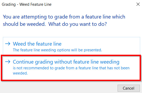
Figure 9.33 – Grading - Weed Feature Line message
- Bringing our attention back down to the command line, we’ll be asked to select a grading site. We’ll want to click inside of the setback line in this case so that the grading object created will generate a surface within each of our setback lines.
- Next, we’ll be asked if we want to apply to the entire length. In our case, we want to type YES and hit the Enter key on our keyboard.
- We’ll then be asked to specify the target elevation. If we refer back to Figure 9.31, we’ll notice that the approximate elevation we would like to target on the street side of the parcel is listed as 763.63. Let’s type this value at the command line and hit Enter.
- Next, we’ll be asked to specify a Cut Format type, where we can accept the default of Slope.
- Then, we’ll be asked to specify a Cut Slope value, where we’ll type in 2:1 (rise over run) and hit Enter.
- The same will then be asked for Fill scenarios. Let’s make the same selection of Slope, and then type 2:1 as the value and hit Enter.
After all steps have been completed, we’ll notice that our grading objects and surface have been created within the setback feature lines of our southeastern parcel, as shown in Figure 9.34:
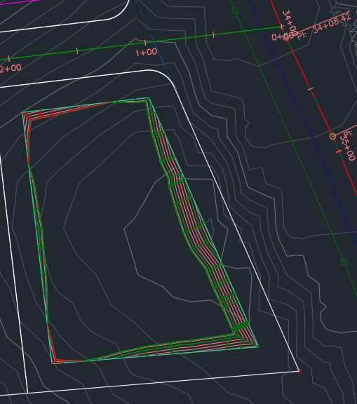
Figure 9.34 – Final grading object and grading surface for our southeastern parcel
Let’s use these same steps applied to our first parcel to continue our grading object and grading surface creation throughout our site, with the exception of our northeastern lot since that appears to be our largest lot with the biggest elevation difference throughout.
For this particular lot, we’ll want to target an elevation relatively close to the existing elevation in the middle of our lot, closest to the cul-de-sac location, which is approximately 744.00. Let’s use this target elevation for this lot in particular.
After applying these steps to all setback feature lines, the last thing we’ll need to do is apply an infill grading object inside each of the grading objects displayed in our lots. Going back up to our grading tools, we’ll select the down arrow in our Grading Type Selection icon (listed as number 7 in Figure 9.30) and select the Infill option. After being selected, we’ll proceed with clicking our left mouse button inside each of the grading objects previously created. As we click inside these areas, you will notice that the boundaries will be highlighted, and a green diamond will appear at the centroid.
After applying these steps to all setback feature lines, the final product should look similar to that displayed in Figure 9.35:
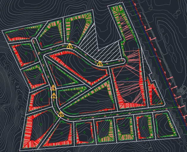
Figure 9.35 – Final grading object and grading surface for our residential subdivision
Summary
We have taken some significant steps throughout this chapter toward developing our general arrangement, and associated modeled objects, to progress our residential subdivision design. We’ve learned how to create right of ways along with individual parcels, and even incorporated some level of automation while doing so. We then jumped into sites and grading tools to establish building pad locations for us to use when it comes time to locate individual houses throughout our residential subdivision design.
In our next session, we’ll replace our land development toolbelt with our roadway modeling toolbelt to continue progressing our residential subdivision. In addition to understanding how we can utilize roadway modeling tools, we’ll also be able to tie our roadway surface models into our land development surface models that we have developed, resulting in a federated proposed residential subdivision surface model that will be used for final display purposes.