
7
Alignments - The Second Foundational Component to Designs within Civil 3D
As mentioned, within any Civil 3D design, Surfaces, Alignments, and Profiles are often considered the three major foundation components required to build a true civil infrastructure design model. In Chapter 6, Surfaces - The First Foundational Component to Designs within Civil 3D, we took a deep dive into surfaces. We learned about several workflows to create, modify, interrogate, and analyze the existing Surface Model that we had generated from survey point data.
In this chapter, we’ll take a similar deep dive into the world of alignments. Not only will we explore alignments in our existing Survey but we’ll also begin to explore how, in many design scenarios, our design models can—and may need to—start with an alignment.
In our design scenario, we will be taking two existing large lots of land and splitting them into smaller parcels of land to essentially generate a residential subdivision. In addition to distributing our parcels, we’ll need to design a road, right-of-way, and easements/setbacks for our houses to be placed on, along with proper drainage and various utilities to serve each property.
With that, in this chapter, we’ll focus on the following key aspects as they relate to alignments in Civil 3D:
- Alignment creation
- Understanding alignment styles
- Alignment manipulation and management
As discovered with surfaces in Chapter 6, Surfaces - The First Foundational Component to Designs within Civil 3D, there are many levels of each foundation 3D geometry to peel to fully understand how integral a part they will play in our overall design. With that, let’s jump right in to continue the momentum we already have going for us.
Technical requirements
The exercise files for this chapter are available at https://packt.link/UoiPn
Alignment creation
In this section, we’ll begin exploring the multiple ways to create an alignment, all while getting a full understanding of the alignment creation tools available to us within the Civil 3D environment. To kick things off, we’ll go ahead and open up our Survey Model.dwg file located in our Practical Autodesk Civil 3D 2024Chapter 7 subfolder.
For design purposes, we’ll need to convert our linework depicting the centerline of York Hwy CL we created back in Chapter 5, Leveraging Points, Lines, and Curves. We’ll need to convert to an alignment so that we have something to tie our design alignment into when we start laying out our subdivision itself. By tying two alignments to each other, we’re able to dynamically design our intersections that will represent the entrance(s) of our site.
Moving over into our Survey Model.dwg file, let’s go ahead and isolate our linework depicting York Hwy CL. To do so, we’ll select our linework, right-click, and select Isolate Objects | Isolate Selected Objects (refer to Figure 7.1):
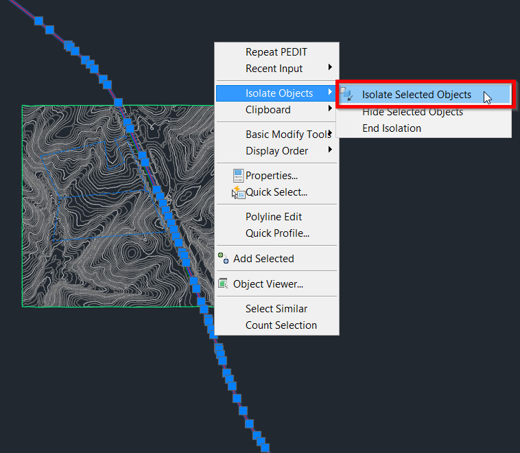
Figure 7.1 – Isolate Selected Objects workflow
Once our linework has been isolated (as shown in Figure 7.2), we’ll notice that the linework depicting York Hwy CL is actually a 3D polyline. If you’ll recall, when we originally created this geometry, we used our survey points to generate this linework.
That said, our points, in addition to having X and Y values (Northings and Eastings), also have Z values (elevations) associated with them as well. Since elevation ranges can vary when creating linework from points, this will, by default, convert the linework to a 3D polyline when we use the JOIN command (a detailed workflow was outlined in Chapter 5, Leveraging Points, Lines, and Curves:
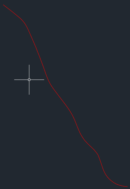
Figure 7.2 – Isolated York Hwy CL
When converting linework to an alignment within the Civil 3D environment, we are limited to the types of objects that we are able to convert to an alignment. As noted in Figure 7.3, object types that we are able to convert to an alignment include lines, curves, and polylines:
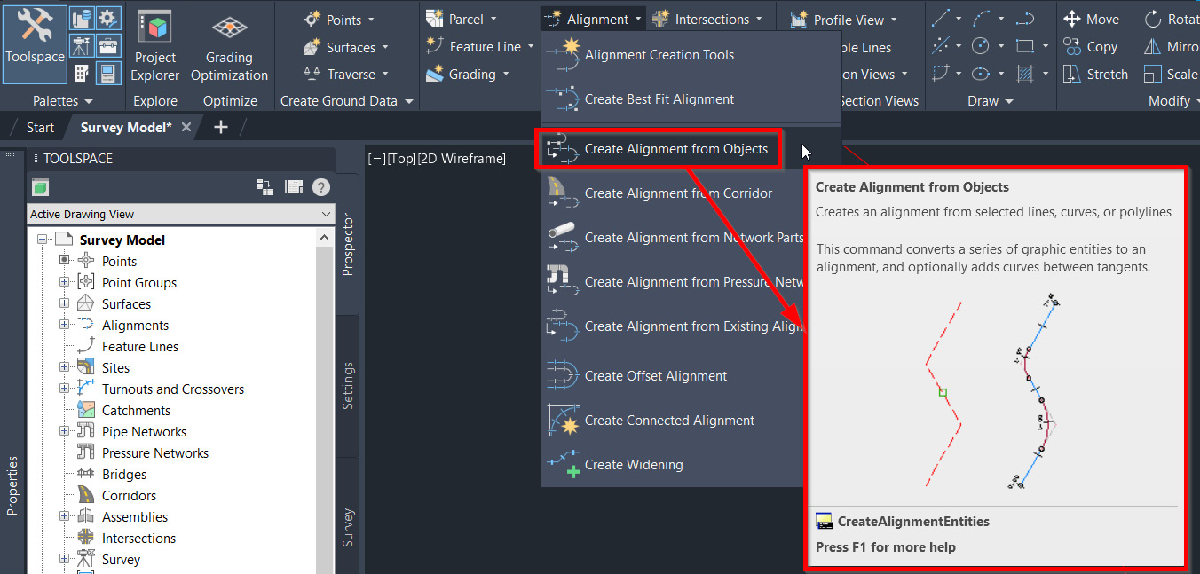
Figure 7.3 – Objects that can be converted to an alignment
Note
It’s important to note that whenever Civil 3D references polylines, the implied object is actually either a 3D polyline or a 2D polyline. When 3D polylines are able to be used to convert to Civil 3D modeled elements, it will specifically call out 3D polylines.
Understanding that with the York Hwy CL linework currently shown in our file as a 3D polyline and that we are unable to convert 3D polylines to an alignment, we’ll need to find an alternative solution for converting our linework to an alignment. Luckily for us, Civil 3D does come equipped with a tool that will allow us to convert 3D polylines to 2D polylines, and vice versa.
This tool can be found by selecting the Modify ribbon, expanding the design panel, and selecting the Convert 3D to 2D Polylines tool, as shown in Figure 7.4:
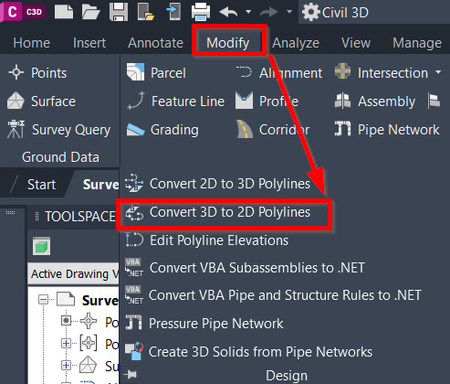
Figure 7.4 – Convert 3D to 2D Polylines
Once this tool has been initiated, we’ll follow the steps detailed at the command line to continue with our conversion process. In our case, we’ll be prompted to select 3D polylines to convert, at which point, we can go ahead and simply select our linework depicting York Hwy CL and hit the Enter key to accept.
The conversion process has now been applied to our linework. If we were to select the linework again, right-click, and select Properties, we’d be able to quickly see that our elected object is no longer being listed as a 3D polyline but as a polyline instead, as shown in Figure 7.5:
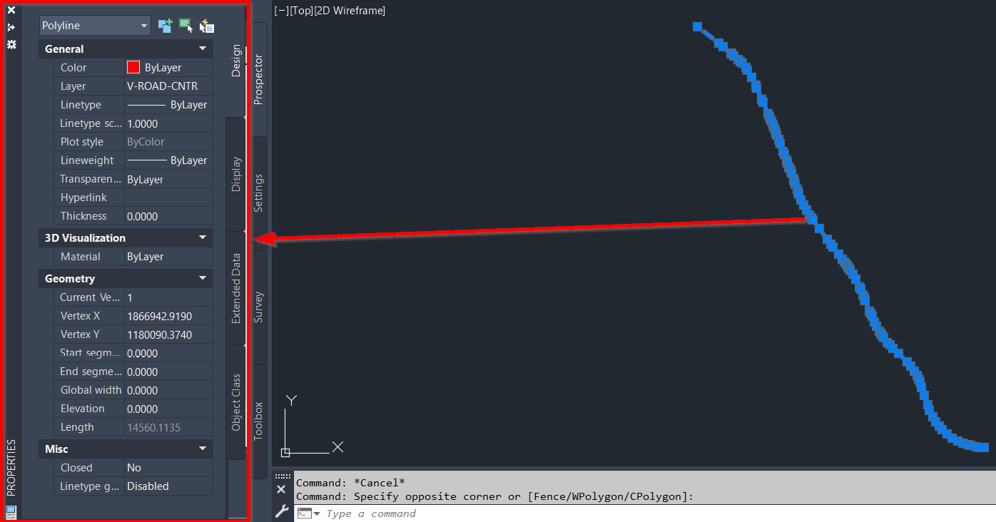
Figure 7.5 – Converted linework from a 3D polyline to a polyline
With our linework converted to a polyline, we can now convert our polyline to an alignment. To do this, we’ll switch back to our Home ribbon, select the down arrow next to Alignment in our design panel, and then select the Create Alignment from Objects option, as shown in Figure 7.6:
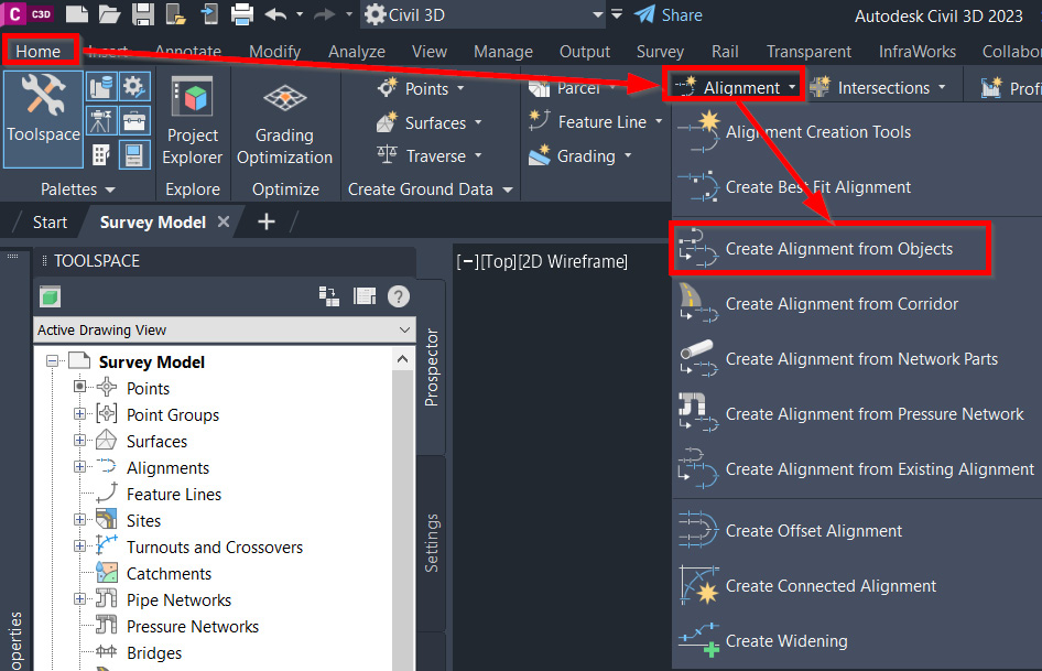
Figure 7.6 – Create Alignment from Objects
Once Create Alignment from Objects has been selected, we’ll be prompted at the command line with the following steps:
- Select lines/arcs or polylines to create alignment: We can go ahead and select our polyline depicting York Hwy CL.
- Press Enter to accept alignment direction or [Reverse]: This option sets our direction and the stationing for our alignment. If we type R and hit the Enter key, this will reverse the direction of our alignment and stationing.
After getting through these steps, we’ll then be presented with a Create Alignment from Objects dialog box, where we will fill out and make the following assignments (also shown in detail in Figure 7.7):
- Name: ALG – Existing York Hwy – FromSurveyPoints
- Type: Centerline
- Alignment style: Existing
- Alignment label set: Major and Minor only
- Conversion options:
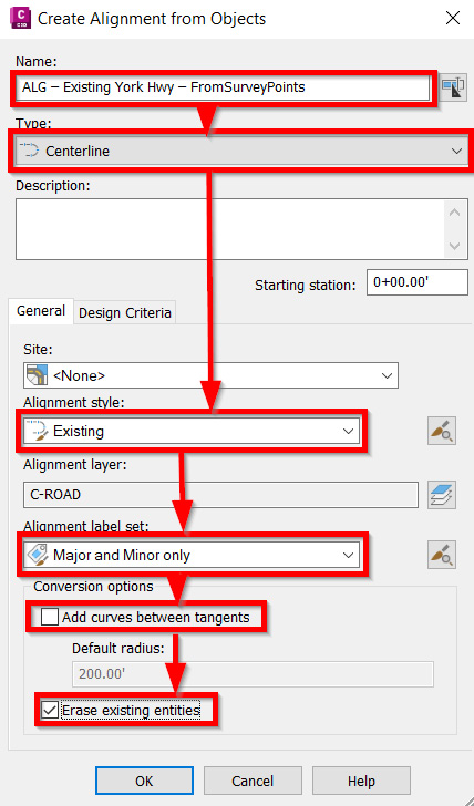
Figure 7.7 – Create Alignment from Objects dialog box
After making the appropriate selections and clicking the OK button, let’s zoom in on our new alignment shown in Model Space. As we zoom in, we can see that the original linework has automatically been removed, with an intelligent Civil 3D alignment created in its place, containing check marks at 50’ intervals and station labels at 100’ intervals (refer to Figure 7.8 for a zoomed-in view):
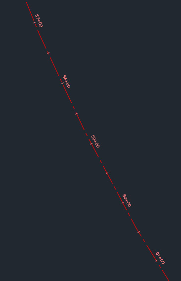
Figure 7.8 – ALG – Existing York Hwy – FromSurveyPoints
Now that our ALG – Existing York Hwy – FromSurveyPoints alignment has been created, let’s go ahead and turn everything back on in our current view within Model Space, by reversing the object isolation that we performed earlier in this section when we wanted to isolate just our York Hwy CL linework.
To do this, we can simply right-click our mouse anywhere in our Model Space and select Isolate Objects | End Object Isolation, as shown in Figure 7.9:
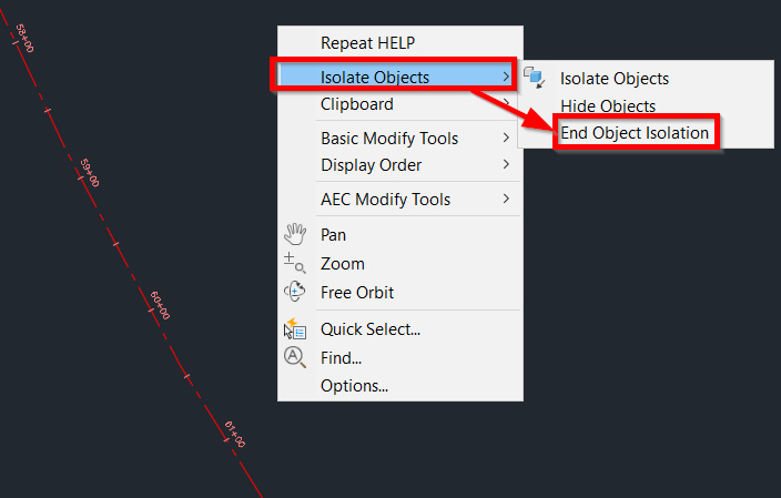
Figure 7.9 – End Object Isolation workflow
With all of our objects visible in our Survey Model file again, let’s zoom out a bit to see the extents of our drawing, which should appear similar to that shown in Figure 7.10:
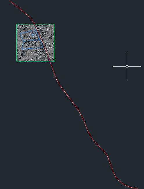
Figure 7.10 – Survey Model zoomed at extents
To ensure that we are keeping our alignments organized, we’ll apply similar practices as we did with our surface creation in Chapter 6, Surfaces - The First Foundational Component to Designs within Civil 3D. With that, we’ll use the following steps to add a level of organization in our files as it relates to our alignments:
- Go back into the Prospector tab in the Toolspace.
- Expand the Alignments category.
- Right-click on Centerline Alignments.
- Select the Create Folder option.
- In the Create Folder dialog box, we’ll identify the New Folder Name value as Existing Conditions.
- Click the OK button.
- Go back into the Prospector tab in the Toolspace.
- Select our ALG – Existing York Hwy – FromSurveyPoints alignment.
- Drag and drop our ALG – Existing York Hwy – FromSurveyPoints alignment into the Existing Conditions folder we just created (the final organization should look similar to that shown in Figure 7.11):
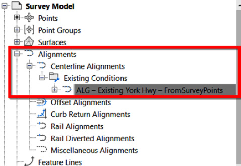
Figure 7.11 – Centerline alignment organization
The final step for us to take as it relates to our existing alignment is to create a data shortcut of our ALG – Existing York Hwy – FromSurveyPoints alignment so that it can be data-referenced in our design files, which will allow us to properly tie our proposed road alignment into them.
The following steps are outlined in Chapter 3, Sharing Data within Civil 3D, and Chapter 5, Leveraging Points, Lines, and Curves. We can right-click on our Data Shortcuts project, select Create Data Shortcuts, and check the box next to our ALG – Existing York Hwy – FromSurveyPoints alignment, as shown in Figure 7.12:
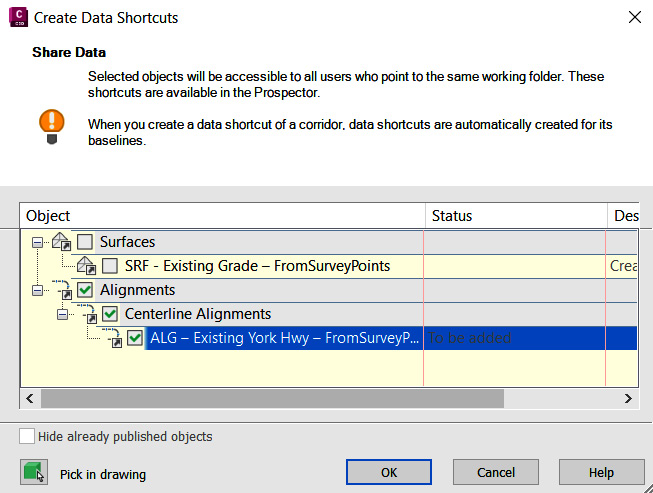
Figure 7.12 – Add ALG – Existing York Hwy – FromSurveyPoints alignment to Data Shortcuts
We’re now ready to save and close out of our existing Survey Model.dwg file and move into our design files. After closing out of our Survey Model.dwg file, Civil 3D will default back to the start screen, where we will select New | Browse templates, as shown in Figure 7.13:
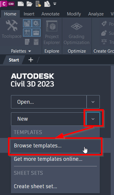
Figure 7.13 – Start screen – Creating a new file from templates
A Select Template dialog box will then appear, at which point we’ll want to navigate to our Practical Autodesk Civil 3D 2024Chapter 7 location, select our Company Template File.dwt file, and select Open in the lower right-hand corner of the Select Template dialog box, as shown in Figure 7.14:
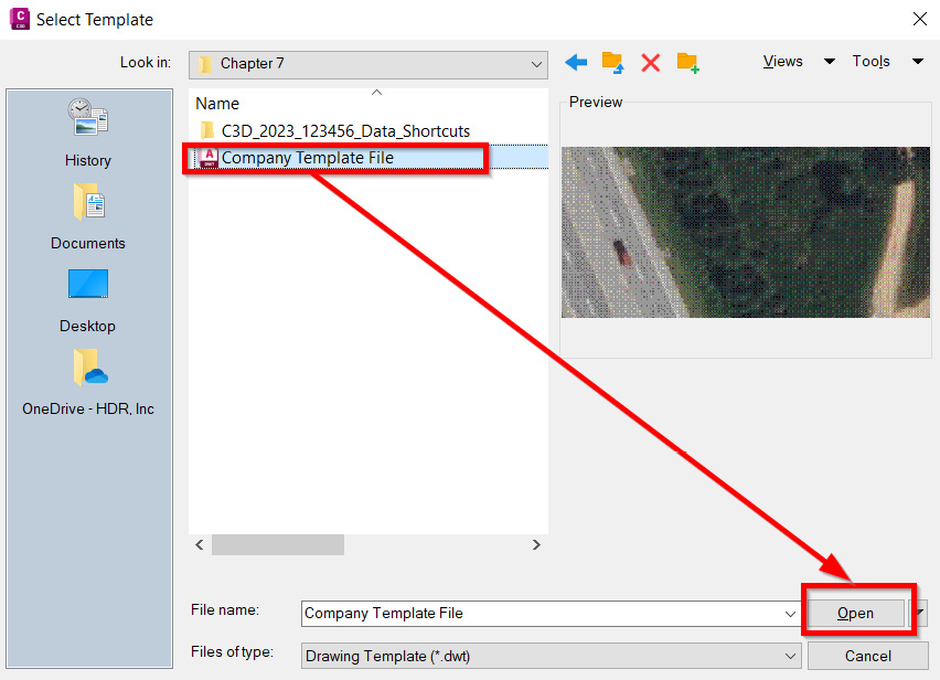
Figure 7.14 – Starting a new file with our company drawing template file
With our new file created using our Company Template File.dwt file, we’ll follow the standard AutoCAD workflows to save our file as Alignment Model.dwg and to attach our Survey Model.dwg file as an overlay, all within our Practical Autodesk Civil 3D 2024Chapter 7 location.
Next, we’ll want to jump back into the Prospector tab in the Toolspace, and then set the Working Folder option of our Data Shortcuts project to the Practical Autodesk Civil 3D 2024Chapter 7 location and select the C3D_2024_123456_Data_Shortcuts project, as shown in Figure 7.15:
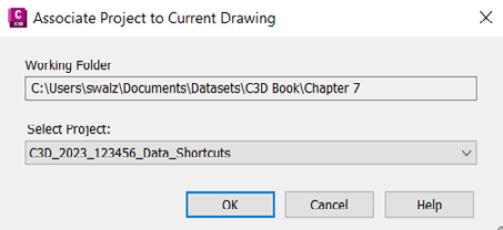
Figure 7.15 – Associate Project to Current Drawing
After our Civil 3D Data Shortcuts project has been associated with our current file, we can then safely create data references of our SRF – Existing Grade – FromSurveyPoints Surface Model and our ALG – Existing York Hwy – FromSurveyPoints alignment into our current Alignment Model.dwg file.
To do this, we need to expand the Surfaces and Alignments categories and our Existing Conditions folders, right-click on each element (shown in Figure 7.16), and select a Create Reference option for each:
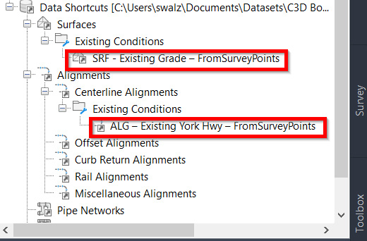
Figure 7.16 – Creating data references of identified Civil 3D objects
Note
Since we have our Survey Model.dwg file already externally referenced into our file (as an overlay), we don’t necessarily need to view the Surface Model, but will need it to reference from a design standpoint a little later on down the road. That said, when we select the Create Reference option for our SRF – Existing Grade – FromSurveyPoints Surface Model, we can apply the _No Display Surface Display style so that it doesn’t get in the way of our selections later on down the road.
With our Alignment Model.dwg file set up, we have all elements available to us to represent and reference the existing built environment. We are now ready to design our residential subdivision. One of the first design objects we’ll want to start with is creating the main road alignment that will allow us to access our residential subdivision.
Depending on your preference, feel free to toggle off the aerial imagery shown in the background. To do this, you can go back to the Geolocation ribbon and select the Map Off option, as shown in Figure 7.17:
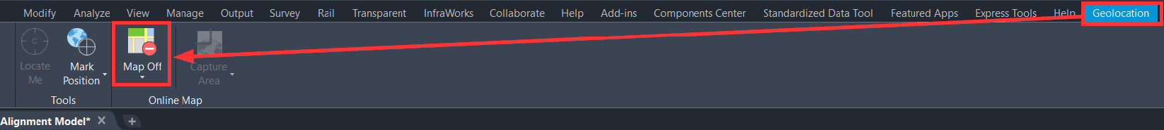
Figure 7.17 – Geolocation: Map Off
To create our Main Residential Subdivision alignment, we’ll go up to the Home ribbon, theCreate design panel, and then select the Alignment Creation Tools option in the Alignment dropdown, as shown in Figure 7.18):
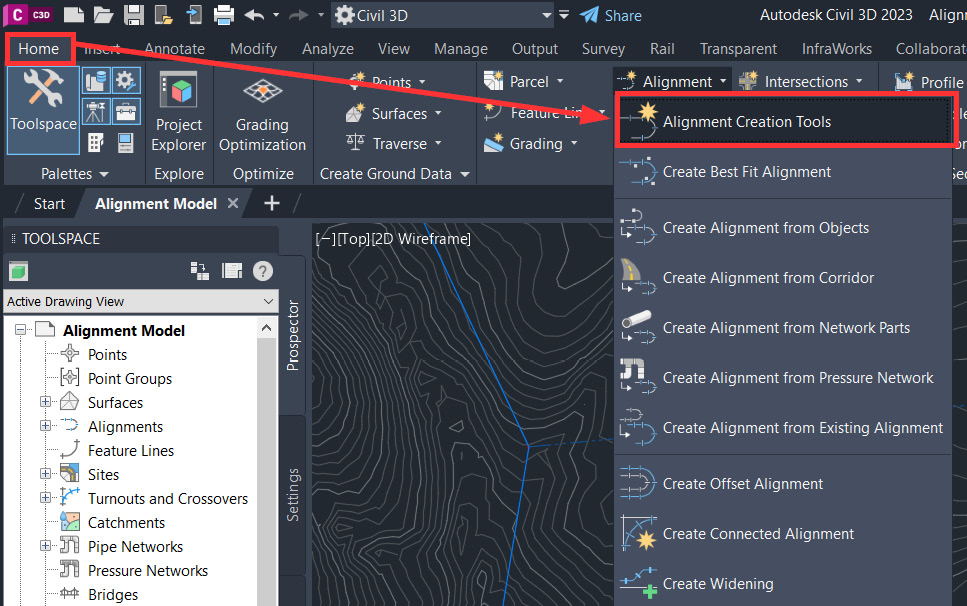
Figure 7.18 – Alignment Creation Tools
Once selected, a Create Alignment dialog box will appear, where we’ll make the following selections, as shown in Figure 7.19:
- Name: ALG - Subdivision Main Road - Access
- Type: Centerline
- Description: Subdivision access road from York Hwy
- Alignment style: Proposed
- Alignment label style: Major and Minor only
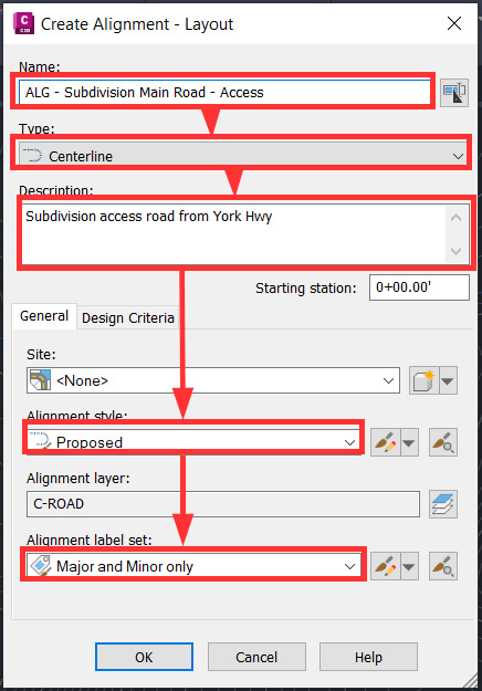
Figure 7.19 – Create Alignment dialog box
Additionally, you’ll notice that in our Create Alignment dialog box, we have General and Design Criteria tabs. If we select the Design Criteria tab before selecting the OK button at the bottom of the Create Alignment dialog box, we gain access to—and have the ability to apply—design-based rules to our alignment.
That said, we’ll want to make the following selections (shown in Figure 7.20) as well, and then we can select the OK button to exit out of the dialog box:
- Starting design speed: 25 mi/h
- Use criteria-based design: Check the box
- Use design criteria file: Check the box
- Use design check set: Check the box

Figure 7.20 – Create Alignment dialog box – Design Criteria
Next, an Alignment Layout Tools toolbar will appear (similar to that shown in Figure 7.21). This toolbar provides all the necessary tools we could ever imagine needing during the alignment creation and editing processes:
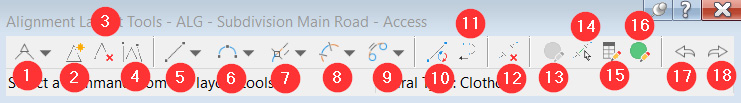
Figure 7.21 – Alignment Layout Tools toolbar
Running through the tools as numbered in the preceding screenshot, we have the following:
- Continuous Geometry Creation Tools: Allows us to lay out our alignment geometry using a Tangent to Tangent method. Using this method allows us to apply or disregard connecting curves automatically during the alignment creation process.
- Insert PI: After our alignment creation has started, we can add new points of intersection (PIs) within our alignment.
- Delete PI: After our alignment creation has started, we can remove PIs within our alignment.
- Break-Apart PI: Allows us to define a break in our alignment geometry by identifying the nearest PI.
- Individual Line Creation Tools: Allows us to individually create Fixed, Floating, or Free lines.
- Individual Curve Creation Tools: Allows us to individually create Fixed, Floating, or Free curves.
- Floating Line with Spiral Creation Tools: Provides two methods for creating a Floating line with spirals.
- Curve with Spiral Creation Tools: Allows us to create Floating or Free curve and spiral combinations.
- Individual Spiral Creation Tools: Allows us to create Fixed or Free spirals.
- Convert AutoCAD Line and Arc: Allows us to convert existing lines and arcs to alignment geometry (a similar concept to the Create Alignment From Object method we performed in our Survey Model.dwg file).
- Reverse Sub-Entity Direction: Allows us to reverse the direction of a Fixed line or curve.
- Delete Sub-Entity: Allows us to remove a sub-entity from our alignment.
- Edit Best Fit Data for All Entities: Allows us to edit regression data associated with our alignment.
- Pick Sub-Entity: Allows us to pick sub-entities within our alignment to analyze.
- Sub-Entity Editor: Allows us to analyze parameters associated with sub-entities within our alignment.
- Alignment Grid View: Allows us to quickly view alignment geometry in table form within our Panorama.
- Undo: Allows us to undo the previous command(s).
- Redo: Allows us to reapply or redo commands that were undone.
Now that we have a decent idea as to which alignment creation tools we have at our disposal within Civil 3D, let’s go ahead and start laying out our ALG - Subdivision Main Road - Access geometry using Continuous Geometry Creation Tools (listed as #1 in Figure 7.21).
If we select the down arrow next to this icon, we’ll want to make sure that the Tangent to Tangent with Curves option is checked. Once checked, we are ready to lay out our ALG - Subdivision Main Road - Access alignment.
By using the midpoint OSNAP (abbreviated from Object Snap), we’ll snap to the Station 34+00 marker along our ALG – Existing York Hwy – FromSurveyPoints alignment, as shown in Figure 7.22. This will essentially mark the intersection and beginning of our ALG - Subdivision Main Road - Access alignment:
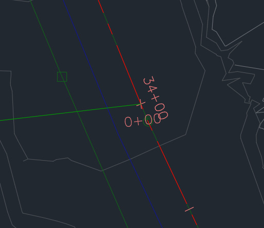
Figure 7.22 – ALG - Subdivision Main Road – Access intersection point with ALG – Existing York Hwy – FromSurveyPoints
Next, we’ll click three more times in different locations within our site to define all four of our PI locations (these locations are indicated with a red circle in Figure 7.23):
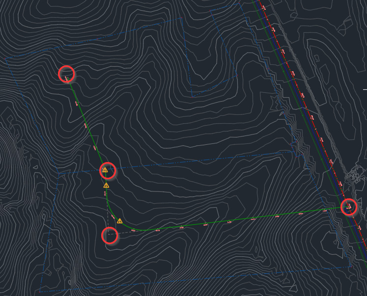
Figure 7.23 – ALG - Subdivision Main Road – Access PIs
Finally, using the same steps we used to create our ALG - Subdivision Main Road - Access alignment, we will now go ahead and create one more alignment to represent the centerline of our subdivision side road.
This subdivision side road will be called ALG - Subdivision Side Road - Cul-De-Sac and will apply the exact same general and design parameters as was assigned to our ALG - Subdivision Main Road - Access alignment.
As we lay our ALG - Subdivision Side Road - Cul-De-Sac alignment out, we’ll want to snap to the 15+00 station marker along our ALG - Subdivision Main Road - Access alignment and place three additional PIs, as indicated in Figure 7.24:
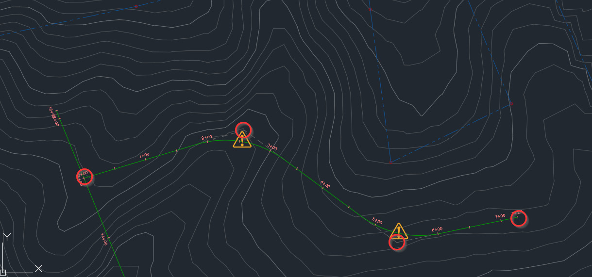
Figure 7.24 – ALG – Subdivision Side Road – Access PIs
With our Existing Surface Model and our Proposed Alignment geometry created, we have officially set ourselves up with a great foundation to continue developing and building up our design. These key foundational items provide the necessary direction and are a base for us to build our design on top of, ensuring that we are fully integrating our Proposed Residential subdivision into the existing built environment. As we progress through the remainder of the chapters, we’ll continue to realize how important these two foundational objects are to Civil 3D designs.
With this understanding, next, we will dive into the nuances of alignments when it comes to styles, manipulation, and design validation.
Understanding alignment styles
Understanding what we’re looking at and the various alignment styles that we have in our arsenal is an important step to fully realizing the benefits of alignment geometry and generating these objects in a dynamic nature. In this section, we’ll familiarize ourselves with the various alignment styles available to us and learn how to display these styles in different circumstances.
For this section, we’ll continue working in our Alignment Model.dwg file, located in our Practical Autodesk Civil 3D 2024Chapter 7 subfolder. Next, we’ll go over to the Toolspace, select the Settings tab, and then expand the Alignment category by clicking the + icon next to Alignment.
We’ll notice that we have the following list of subcategories associated with alignments (also displayed in Figure 7.25):
- Alignment Styles: Here, we will be able to view our comprehensive list of available display styles associated with alignment geometry.
- Design Checks: Here, we will be able to specify additional design parameters that need to be applied to our alignment lines, curves, spirals, and tangent intersections. As we set these parameters here, we can add to our design check sets for a fully comprehensive check of individual sub-entities that make up our alignment.
- Label Styles: Here, we will be able to view our comprehensive list of available label styles that can be applied to our alignment geometry for stationing and annotation purposes; these can also display specified symbology.
- Table Styles: Here, we will be able to view our comprehensive list of available table styles that can be displayed for sheeting purposes as they relate to our alignment geometry.
- Commands: Here, we will be able to view a comprehensive list of available commands that can simply be typed into our command line to perform specific tasks associated with alignments:

Figure 7.25 – Toolspace | Settings tab: Alignment Styles expanded
Starting with Alignment Styles, if we click on the + icon next to it, we will then see that comprehensive list of alignment styles that reside in our current drawing.
Note
These are also contained within our Company Template File.dwt drawing template that we created as a starting point for new files. That said, all styles listed from here on will be included in any new file, provided you are using the Company Template File.dwt as a base.
Types of alignment styles
Once expanded, we’ll see the following list of alignment styles that can be applied to our Alignment objects within our current file for display purposes (also refer to Figure 7.26):
- Basic: Applying this display to our alignment will essentially inherit the layer properties that the alignment has been assigned to
- Existing: Applying this display to our alignment allows us to display it as a background object during the plotting process
- Intersection Basic: Applying this display to our alignment will typically be utilized during intersection designs
- Layout: Applying this display to our alignment will place lines, curves, and spirals on separate layers with different color assignments that will allow us to quickly visually locate each type of sub-entity
- Offsets: Applying this display to our alignment will typically be utilized as we generate offset alignments to project, or target, our corridor subassemblies to
- Proposed: Applying this display to our alignment allows us to display as a proposed, or bold, object during the plotting process:

Figure 7.26 – Alignment styles
Alignment design checks
Next up are our design checks that we can apply during alignment creation and design validation processes. If we click on the + icon next to Design Checks, we will then see a comprehensive list of design checks that reside in our current drawing.
Once expanded, we’ll see the following list of design checks that can be applied to our Alignment objects within our current file (also refer to Figure 7.27):
- Design Check Sets: Allows us to apply multiple design parameters to our Alignment objects
- Line: Allows us to define individual design parameters associated with lines specifically
- Curve: Allows us to define individual design parameters associated with curves specifically
- Spiral: Allows us to define individual design parameters associated with spirals specifically
- Superelevation: Allows us to define individual design parameters associated with superelevations specifically
- Tangent Intersection: Allows us to define individual design parameters associated with tangent intersections specifically:
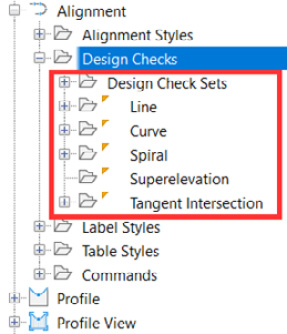
Figure 7.27 – Alignment design checks
Alignment label styles
Next, we’ll visit our alignment label styles. With that, we’ll go ahead and click on the + icon next to Label Styles, at which point we’ll then see a comprehensive list of alignment label styles that reside in our current drawing.
Once expanded, we’ll see the following list of label styles that can be applied to our alignments within our current file for annotation display purposes (also displayed in Figure 7.28):
- Label Sets: Allows us to apply multiple label styles to our alignments as a comprehensive set
- Station: Allows us to create and apply individual station labels to our Alignment objects
- Station Offset: Allows us to create and apply individual station offset labels to our Alignment objects
- Line: Allows us to create and apply individual line labels to our Alignment objects
- Curve: Allows us to create and apply individual curve labels to our Alignment objects
- Spiral: Allows us to create and apply individual spiral labels to our Alignment objects
- Tangent Intersection: Allows us to create and apply individual tangent intersection labels to our Alignment objects
- Point of Intersection: Allows us to create and apply individual PI labels to our Alignment objects
- Cant Information: Allows us to create and apply individual cant labels to our Alignment objects:
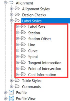
Figure 7.28 – Alignment label styles
To add alignment labels, navigate to the Annotate tab, then click the drop-down arrow on the Add Labels button. Then, navigate to Alignment, and you will see all the options you have for creating Alignment Labels:
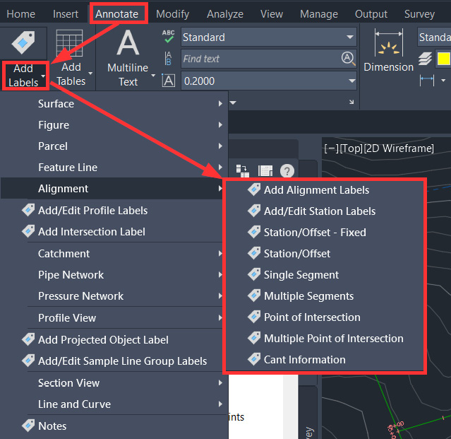
Figure 7.29 – Workflow for adding alignment labels
Alignment table styles
Next, we’ll visit our Alignment table styles. With that, we’ll go ahead and click on the + icon next to Table Styles, at which point we’ll then see a comprehensive list of Alignment table styles that reside in our current drawing.
Once expanded, we’ll see the following list of table styles (also refer to Figure 7.30 for a detailed breakdown of Alignment table styles in our current file) that can be added to our drawings for sheeting purposes:
- Line: This table style will be dynamically linked to our alignment geometry and will display specified information related to the lines contained within
- Curve: This table style will be dynamically linked to our alignment geometry and will display specified information related to the curves contained within
- Spiral: This table style will be dynamically linked to our alignment geometry and will display specified information related to the spirals contained within
- Segment: This table style will be dynamically linked to our alignment geometry and will display specified information related to all segments contained within:
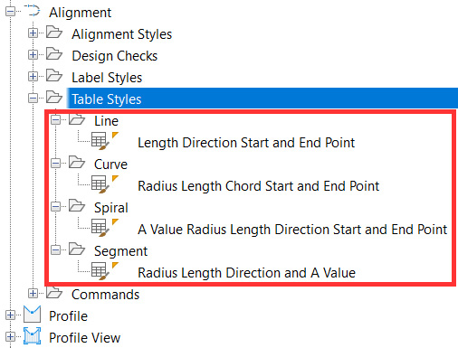
Figure 7.30 – Alignment table styles (detailed version)
With that overview of all applicable styles that can be applied to our alignments out of the way, let’s get a better understanding of what some of these actually mean and represent, how we can apply different styles in different circumstances and scenarios, and how we can enhance our overall understanding of alignments and the impact they can have on our designs.
Alignment manipulation and management
In a majority of cases, we’re going to want to maintain the display of our alignments as we create them. Occasionally, we’ll come across a need to make some adjustments to how we are displaying our alignment, station referencing, how we are manipulating our alignment geometry, and maybe even applying a different set of design parameters to our Alignment objects.
To access any of these options, we can simply select our Alignment object in Civil 3D, right-click in Model Space, and select the Alignment Properties option. Once selected, we’ll be presented with our Alignment Properties dialog box.
Along the top of our Alignment Properties dialog box, we have the following series of tabs, where we can access these manipulation options mentioned, as shown in Figure 7.31:
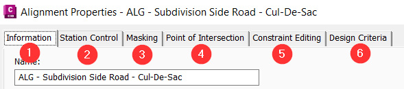
Figure 7.31 – Alignment Properties: manipulation options
- Information: Allows us to make changes to our alignment name, description, and styles
- Station Control: Allows us to make changes to our station information and the starting point of our alignment and add station equations if needed
- Masking: Allows us to hide specific station ranges along our alignment if needed
- Point of Intersection: Allows us to change the display of PIs if not implied by fixed tangent intersections
- Constraint Editing: Allows us to change the way our tangency and parameter constraints function while performing edits to our alignment
- Design Criteria: Allows us to add different parameters to our alignment for design check purposes
In addition to the manipulation options available to us in the Alignment Properties dialog box, if we were to simply select our Alignment object in our Model Space, we would then be able to view the Context ribbon along the top of our screen, as shown in Figure 7.32:
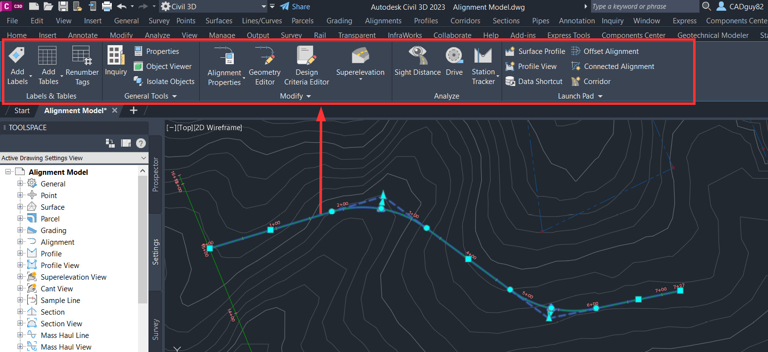
Figure 7.32 – Alignment Context ribbon
The Contextual ribbon is a new set of options that will display in ribbon form and will allow us to perform additional edits, inquiries, and analyses on our selected geometry. In this case, we have selected our alignment, in which an Alignment Contextual ribbon appears that allows us to further interrogate, manipulate, and analyze our ALG - Subdivision Side Road - Cul-De-Sac alignment.
Running from left to right as shown in Figure 7.32, we have the following panels with tools available to us:
- Labels & Tables: Grants us access to various annotative tools
- General Tools: Grants us access to various inquiry tools that will display information associated with our selected alignment
- Modify: Grants us access to various tools that allow us to manipulate our alignment geometry
- Analyze: Grants us access to various analysis tools to further examine our alignment geometry
- Launch Pad: Grants us access to major tools/workflows that will enable further development of our design and collaboration
Note
Analysis tools available in our Alignment Contextual ribbon will require a profile to be created along our alignment first.
As we progress through our design, we will revisit many of these tools and capabilities available to us to further validate our alignments and design in general. The unfortunate reality at this point in our design progression is that we just don’t have enough design objects created at the moment to truly take advantage of these tools and capabilities available to us in the Contextual ribbon.
Summary
With that, although we have performed a bit of discovery as it relates to uncovering how big a part alignments play in our design, there are many additional components that we need to dynamically link to alignment geometry to truly appreciate and realize the value they bring to the table.
That said, although we have two foundational Civil 3D objects created, we need to continue progressing further to tie our third foundation Civil 3D object into the mix, which will really bring to light how critical these steps are at the beginning of our designs.
In our next chapter, we’ll begin exploring Profiles that will be referenced and tied to our first two foundational objects (Surfaces and Alignments). Once we’re able to form a dynamic link between all three of these foundational objects, we can begin exploring additional design and analysis tools that are not currently available to us.