
3
Sharing Data within Civil 3D
Now that we understand the benefits of configuring styles and your overall drawing settings, along with the importance of template creation, we can begin diving into best practices for managing design files and modeled objects throughout the project design development phases.
As much as we’d all like to create and pack all Civil 3D objects into one file for an entire project, this concept just isn’t practical for 95% of projects you’ll work on, especially if there are many objects being modeled that require dynamic interaction. On top of this, most engineers working on large projects distribute the workload among their teams to handle the size of the project, but also to expedite the creation of the project.
Managing designs and objects with Civil 3D can seem like a very daunting and complex process at first, but we’ll soon realize that it’s actually a very simple and straightforward process once we understand how everything gets pieced together.
Civil 3D is a powerful platform and this chapter will demonstrate how to scale your workflows with what we will refer to as data shortcuts to include more team members for larger project sizes while maintaining efficiency and keeping your design files manageable.
In this chapter, we will cover the following topics:
- Understanding file relationships
- Learning how data shortcuts work
- Creating data shortcuts within Civil 3D
Technical requirements
The technical requirements of this chapter are identical to the previous chapters. Please refer to the requirements listed in Chapter 1, Introduction to Civil 3D, for reference.
The exercise files for this chapter are available at https://packt.link/UoiPn
Understanding file relationships
When starting any new endeavor, it’s best to enter with a game plan or strategy for success. Handling project designs within Civil 3D is no different; provided we take some quick measures up front to identify all the different Civil 3D modeled objects and project team members required to fulfill the project design requirements, we’ll be able to ensure that we hit the ground running and maintain efficiency throughout the progression of our designs.
As we know, Civil 3D is essentially a vertical application that extends the functionality of Autodesk’s AutoCAD platform, so we already have a good understanding of how external references are managed throughout the design process. While Civil 3D introduces a new level of complexity with the ability to generate civil infrastructure-related model objects, we also have the ability to data reference individual modeled objects, via data shortcuts, from one file to another as needed, eliminating the requirement to externally reference a drawing file wholesale.
I tend to use data shortcuts fairly extensively in order to manage projects and streamline the use and storage of data. They operate much like an external reference, in that when an externally referenced drawing is changed, you see the changes in the referenced drawing by reloading the reference, but you cannot modify the reference without opening the file it originated in.
Data references are similar but instead of referencing a drawing, you are referencing Civil 3D data and entities. For example, when a surface changes in file 1 and is being referenced in file 2, the user designing in file 2 can synchronize the reference and see the changes in their drawing instantly. The data that is referenced can be used for analysis, representation, calculations, and labeling, but it cannot be modified, so there is no risk of accidental modifications or deletions.
In addition to knowing when it may be appropriate, or ideal, to use external references versus using data references, it is equally important to properly organize and segregate the Civil 3D files by model and data types that will be used for your project. With that in mind, my recommendation (which is a trusted methodology across the industry) is to categorize project design files into one of the following three types of files: model, reference, or sheet files. This provides some additional means of properly managing files and design objects, as well as providing additional benefits of providing flexibility to allow multiple team members to update design files as needed.
Let’s take a look at each of these file types.
Model files
With this structure, model files are intended to contain Civil 3D objects (both existing conditions and proposed design objects) that are housed in separate files dictated by the type of design objects contained within. Model files use data references to bring in the dynamic design data and use external reference files as simple overlays for the context of the entire combined drawing.
The following are a few examples of files that can be considered model files, along with some additional details of how they are intended to be set up and used.
Survey model
When the original survey file is received, it should be placed in a received folder to be left as an untouched, original file. A new survey model drawing will be created using the Civil 3D template and all survey information will be copied and pasted from the original file into this new file. Any surfaces or other Civil 3D entities included with the survey should be exported into a LandXML file, the .xml file placed into the received folder, and then imported into the new survey model file created.
The survey file should contain all existing Civil 3D objects. These can include, but are not limited to, surfaces, alignments, and pipe networks. These objects should have data shortcuts created for them and be available within the Data Shortcuts folder. If the surfaces, pipe networks, alignments, and so on have not been previously assigned a name, the name should reflect their status as an existing entity. For example, a surface created from data received with the survey should be named something similar to Existing Grade.
In the event that surface files are too large to reside within the survey model file, it is acceptable to place them in a secondary file. This file should follow a standard naming convention, such as Topographic Survey Model. A data shortcut should be created for the existing surface data.
Furthermore, the survey model file is considered to be an exception to the rule, in the sense that this is the only model file that will be set to a specific scale and contain all labeling and annotation that will be shown on the sheets.
Alignment model
In the alignment model file, alignments for roadways, dams, or linear structures will be designed. Pipe network alignments will not be placed in this file, as they are dependent on pipe network layouts. Data shortcuts should be created for these entities and the naming of proposed alignments should reflect what they represent. For example, if an alignment is set to a road named Main Street, the alignment should be named Main Street.
Grading model
In the grading model file, proposed surfaces will be designed. All design elements relating to the finished grading should be kept in this file, including any profiles that may be used for the purpose of creating grading objects or corridors.
Many times, grading is initiated with a corridor model, which requires a profile to be created from an alignment. The alignment should be referenced in the data shortcut created from the alignment model file, and the design profile created in the grading model file. In turn, there should be a data shortcut created for this design profile for use in other model files, as needed.
The naming of the proposed surface(s) should reflect what the surface is for. For example, if the surface is for the entire site grading of a subdivision, it should be named Site Grading Subdivision. If it is for a road grading of Highway 123, it should be named Highway 123 Roadway. Data shortcuts should be created for these surface objects to help maintain flexibility and control of specific sections of a design.
Utility model
In the utility model file, pipe networks will be designed. All design elements relating to the pipe network will be kept in this file, including any profiles that may be used for designing the utility system. Depending on the complexity of the site, it may be necessary to create several utility model files, one for each different type of piping network, such as storm, sanitary, water, and gas. Each pipe network should be named logically, such as Sanitary Sewer or Water Main. Data shortcuts should be created for these structure and pipe objects separately again for finer control as modifications need to be made.
Reference files
Next up are reference files, which are intended to contain/represent 2D geometry and static elements and annotation. Reference files would include content such as surveyed planimetrics, civil site plan geometry, and erosion control BMPs.
The following are a few examples of files that can be considered reference files, along with some additional details of how they are intended to be set up and used.
Site plan reference file
In the site plan reference file, there should be points created for coordinate table generation (commonly used for site staking plans), if required. These points should be placed in a point group named appropriately to reflect what they represent. For example, if points are placed to designate a parking lot layout, the point group should be named Parking Lot Layout Points.
If alignment tables need to be created, the alignment(s) will be data referenced into the site plan reference file. Tags will then be assigned, and tables generated, from the alignment as required.
Generally, topographic data is not shown on site layout plans, but if required, it will be brought into the site plan model file via a data reference from the survey and/or the grading models.
Grading reference file
In the grading plan reference files, there should be the existing and proposed surfaces data referenced in from the survey and grading model files. All surface labels and any needed tables will be created in this file at the scale designated.
Utility plan reference file
In the utility plan reference files, pipe networks, alignments, and surfaces will be data referenced into this model from the alignment model files. Labels, tables, and any other necessary annotation will be placed in this file at the scale designated.
Profile reference file
In the profile reference file, all alignments, design profiles, and surfaces will be data referenced into this reference from the model files. This data will be used to produce profile views within this file. Labels, tables, and any other necessary annotation will be placed in this file at the scale designated.
Section reference file
In the section reference file, all needed alignments, design profiles, pipe networks, and surfaces should be created with data references. This data will be used to produce section views within this file. Labels, tables, and any other necessary annotations will be placed in this file at the scale designated.
Sheet files
Lastly, sheet files are the final product of the project. The construction of the sheet files will consist of externally referencing both the reference and model files, along with sheet borders, general notes, north arrows, and any additional sheet-specific annotation.
Following a project structure like this has many benefits, ranging from overall design file optimization to promoting work-sharing opportunities across your project team(s). Regardless of the size of your project and team(s) involved, incorporating this methodology can only increase efficiency in your design process. This breakdown of work ensures that project team(s) are able to stay focused on all of the various tasks required by allowing multiple team members to work on different files and design models simultaneously.
Now, let’s dive into the details of how data shortcuts work for such a flexible and dynamic work structure.
Learning how data shortcuts work
As mentioned, data shortcuts allow project teams to share and reference specific Civil 3D modeled objects from one drawing to another. This functionality allows project teams to maintain high levels of efficiency by not only referencing just the Civil 3D objects needed at that time but also limiting the amount of content and data residing in your current drawing.
Data shortcuts work by decentralizing a project’s content, allowing each large entity (i.e., a surface, pipe networks, and corridors) to exist in its own separate drawing. By creating data shortcuts, you tell each drawing which drawings are related to it or are in the same project, and then are able to sample that data within the current drawing.
The alternative to this is housing each large object in the same file, dramatically increasing the file size and similarly reducing the maneuverability within that drawing. This separation of objects is not only beneficial for effective space allocation within files but also allows for more collaboration on files, having team members perform actions simultaneously for faster project completion.
Often, especially with earlier releases with Civil 3D, the size of the file can increase exponentially, commonly referred to as file bloat, causing significant delays and refresh rates while performing even the simplest of commands. It is important to note that, starting with Civil 3D release 2024, Autodesk made significant improvements to overall performance and file optimization to alleviate some of these issues experienced with earlier releases.
Getting your Civil 3D environment ready to use data shortcuts is best configured at the beginning of a project, similar to setting up your drawing settings and drawing templates, as discussed in Chapter 2, Setting up the Design Environment. There are essentially two functions needed for the implementation of data shortcuts: creation and referencing. The data shortcuts must be created within the file that the data exists in, and then they must be referenced in the file where the data needs to be shown or used.
The first step in getting your Civil 3D environment ready to use data shortcuts is to pull up the Toolspace again and go to the Prospector tab, as shown in Figure 3.1:
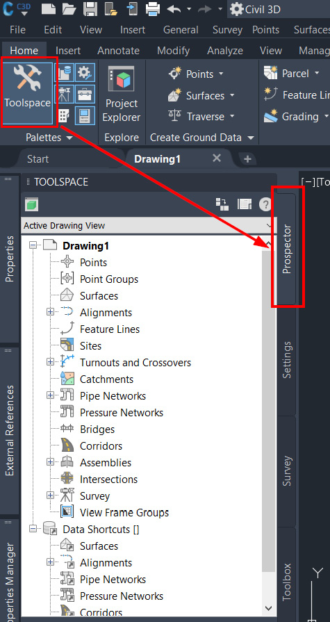
Figure 3.1 – Toolspace Prospector tab
Next, we’ll scroll down to the area in Prospector that is labeled Data Shortcuts [], right-click on the text, and select Set Working Folder…, as shown in Figure 3.2:
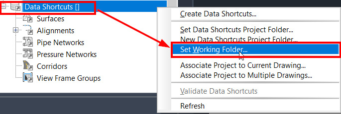
Figure 3.2 – Set Working Folder… selection
In the Set Working Folder dialog box, we must first identify and then navigate to the location in which we would like to store our project’s data shortcuts (refer to Figure 3.3):
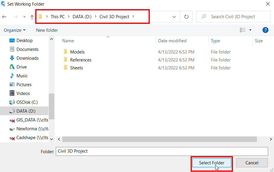
Figure 3.3 – Set Working Folder dialog box
My recommendation would be to store these at the root of your Project Design folder. We will then assign the data shortcuts project folder a unique naming convention to ensure that we can quickly identify it later on, if needed, and keep it consistent when we associate them with the corresponding project design files.
Once selected, we now need to go back to Prospector, right-click on Data Shortcuts [] again, and now select New Data Shortcuts Project Folder…, as shown in Figure 3.4:
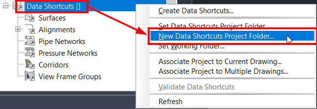
Figure 3.4 – New Data Shorcuts Project Folder…
A recommended practice is to give the data shortcuts project folder a standard naming convention consisting of the Autodesk program, version, project number, and, finally, the Data_Shortcuts annotation to alert others within the project of the purpose of the folder and files contained within and it is not just a working or temporary folder. For example, a project being produced with Civil 3D version 2024 with a project number of 123456 would have a data shortcut project folder named C3D_2024_123456_Data_Shortcuts, as shown in the New Data Shortcuts Folder dialog box in Figure 3.5:
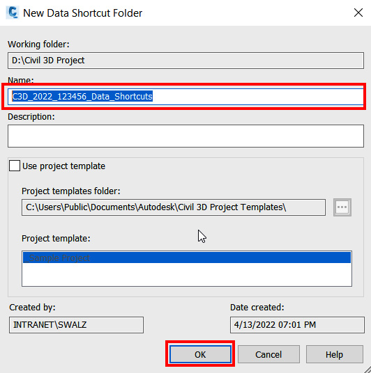
Figure 3.5 – New Data Shortcut Folder dialog box
Immediately after your new data shortcuts folder has been created, you’ll notice that the path and name of the data shortcuts project are now listed in brackets next to Data Shortcuts in Prospector. Your drawings, which need to have access to the project data, will now need to be associated with that project folder. This is done by right-clicking on the Data Shortcuts section of Prospector one final time and selecting Associate Project to Current Drawing…, as shown in Figure 3.6:
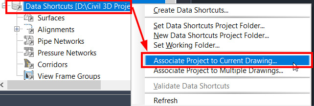
Figure 3.6 – Associate Project to Current Drawing…
Note
In Figure 3.6, you’ll notice there is an Associate Project to Multiple Drawings… option. Selecting this option allows you to create your drawing first and then apply the project association process to all files in a given folder or subfolder. This practice is not ideal, but it’s important to note that it is an available option if these steps are missed during the initial project setup.
Once the Associate Project to Current Drawing dialog box appears, simply select the data shortcuts project you just created (refer to Figure 3.7) and you’ll be all set to move forward:
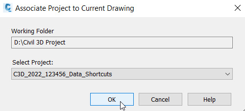
Figure 3.7 – Associate Project to Current Drawing dialog box
It’s important to note that each file where Civil 3D modeled objects are being developed will need to be associated with the corresponding project. Associations ensure that the drawing files retain the location where the project data should be pulled from. Once the drawing is properly associated with the project, you may also notice that the drawing title header at the very top of your Civil 3D session will also reflect which project it is assigned to.
Now that we’ve learned about how data shortcuts work within a larger project, we can take the next step to collaborate further with our designs.
Creating data shortcuts within Civil 3D
Now that we know how to configure data shortcuts and set our project design up from the get-go, let’s dive into creating and linking specific Civil 3D modeled objects from one drawing to another. We’ll also look into some quick management tips and recommended practices for sharing Civil 3D modeled objects.
As we create Civil 3D objects (i.e., surfaces, alignments, gravity/pressure networks, corridors, etc.), we can begin to think through what additional types of model and reference files will be needed for the detailed design in preparation for sheet file creation.
Thinking through what that may look like, let’s use the example of an existing surface created in our survey file. What other types of design files (model and/or reference) will need to reference and display the existing surface for detailed design purposes? A quick analysis would determine that the existing surface would need to be present in the proposed grading model, utility, profile, and section model files.
In some of these files, other Civil 3D objects will need to be present as well; for example, the existing utility Civil 3D objects would need to be present in the proposed utility model file to be able to tie proposed networks into the existing one. In that same sense, existing utility Civil 3D objects would not be required to be present in the proposed grading model.
So, let’s run through the process of creating data shortcuts. As shown in Figure 3.8, we can see that within our existing survey model file, we have an existing surface created. To allow for this type of Civil 3D object to be data referenced into other files, we’ll need to right-click on the data shortcuts project we created earlier and select Create Data Shortcuts….
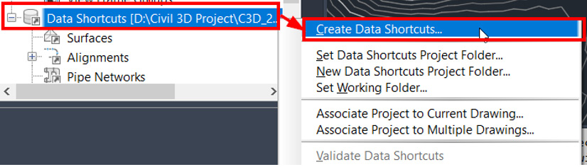
Figure 3.8 – Create Data Shortcuts… on a surface model
After selecting the Create Data Shortcuts… option, you’ll be presented with a Create Data Shortcuts dialog box (as shown in Figure 3.9). In this dialog box, you’ll have the opportunity to add Civil 3D modeled objects from the current drawing to your data shortcuts project.
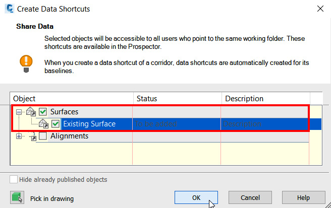
Figure 3.9 – Create Data Shortcuts page of a surface model
In this case, we have the opportunity to create data references for both Surfaces and Alignments. If we select the checkbox next to Surfaces and then select the OK button at the bottom of the dialog box, we can then share these particular Civil 3D modeled objects across multiple drawings, provided they are associated with the same data shortcut project.
After selecting OK, you’ll notice that Existing Surface has been added to the data shortcuts project, as shown in Figure 3.10. As we create new files or open existing files that are associated with the same data shortcuts project, we’ll be able to data reference in the existing surface to further our design:
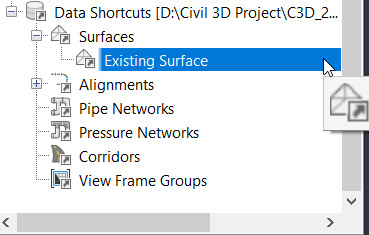
Figure 3.10 – Surface model data shortcut
To further enhance our data referencing project management, we also have the ability to create folders to organize our Civil 3D objects. This definitely comes in handy as project designs become more complex. Thinking simplistically, we can create Existing and Proposed folders within each Civil 3D modeled object. More complex projects can expand upon this by creating site- or area-specific folders, main alignment or roadway folders, utility use folders, and so on.
One thing to note is that folder creation can occur at the current drawing level, as well as the Data Shortcuts level. If we were to create this folder structure at the drawing level, we would need to right-click on the Civil 3D modeled object, in this case, Surfaces, and select the Create Folder option (refer to Figure 3.11):
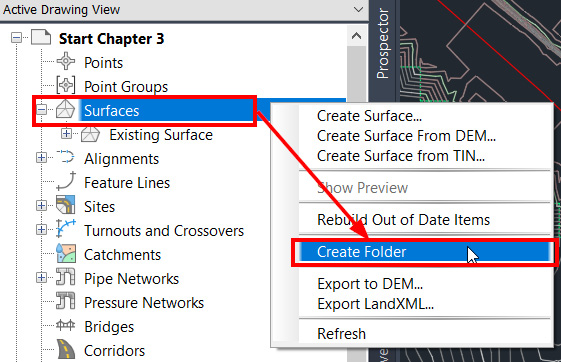
Figure 3.11 – Surface model data shortcut
In the Create Folder dialog box that appears, we can type the name Existing and click OK (refer to Figure 3.12):
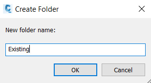
Figure 3.12 – Create Folder
Once created, we can then select Existing Surface, which has already been created, and then drag and drop it into the Existing folder, as shown in Figure 3.13:
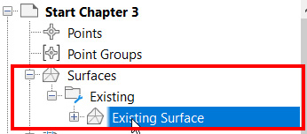
Figure 3.13 – Reorganizing Existing Surface at the drawing level
If we now go back to our data shortcuts project, shown in Figure 3.14, right-click on Existing Surface that we just added, and select Remove, the surface will then be removed from the data shortcuts project.
When we recreate this data reference moving forward (going through steps outlined earlier in this section and shown in Figures 3.8–3.10), we can now see that an Existing folder has been created automatically, and Existing Surface resides within, as shown in Figure 3.14:
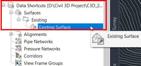
Figure 3.14 – Add Existing Surface with the drawing level folder structure
Alternatively, if we decide to manage folders at the data shortcuts level, and not within each individual drawing, we have the opportunity to do so by right-clicking on the Civil 3D modeled objects in our data shortcuts project and selecting the Create Folder option here, as shown in Figure 3.15:
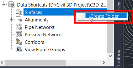
Figure 3.15 – Creating a folder in the data shortcuts project
After we create the folder and create the data reference again, you’ll notice that Existing Surface is added, but uncategorized, as shown in Figure 3.16. We’ll then need to select Existing Surface in the data shortcuts project and drag and drop it into the Existing folder:
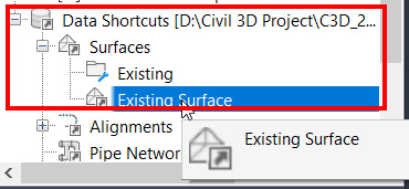
Figure 3.16 – Reorganizing Existing Surface in the data shortcuts project
Out of the two options, my personal preference is to create folders and manage them at the data shortcuts project level. With this option, it’s a one-and-done kind of deal. Although Civil 3D objects are not automatically categorized as they’re created, it really shines a light on proper data shortcuts management and driving consistency across your entire project design.
As we begin to expand our teams involved in these projects and introduce more files and data management requirements, data shortcut project management has the potential to become a full-time job if not handled properly. With that, it is ideal to handle folder structures and proper organization of Civil 3D modeled objects in one location (the data shortcuts project), rather than all individual files that are created for the project that contain Civil 3D modeled objects.
Summary
As covered in this chapter, there are many things to consider when setting up your project to ensure that it can be properly managed throughout the design phase. Depending on the size of your design team and project scope, proper file organization and referencing procedures/workflows can be critical to maintaining high levels of design and collaboration efficiency.
In this chapter, we learned how Civil 3D allows for more efficient file management for not only saving space and maintaining maneuverability within drawings but also allowing teams to collaborate easier between phases of a project, as well as working simultaneously together. This can be crucial in today’s real world of increasingly complex design projects.
The majority of Civil 3D design projects today will require creating and managing multiple data shortcuts with multiple external references, and this up-front management strategy can save hours and days for your team as work is coming in and the project clock starts ticking.
As we jump into the next several chapters, we’ll begin to realize how data referencing can be utilized to our advantage. In the next chapter, we will begin to get stuck into Civil 3D for more hands-on work past the foundational understanding of how the strategies of this program work and why they do in this way.
We’ll also begin to pull all of the design pieces that we’ve learned in the first three chapters together and understand how all of these settings, configurations, and workflows can be applied within an actual project design setting.