Polymer nanocomposites for aerospace applications
J. Njuguna, K. Pielichowski and J. Fan, Cranfield University, UK and Cracow University of Technology, Poland
Abstract:
Advances in nanotechnology will lead to improvements in capabilities across a spectrum of applications. The uses of polymer nanocomposites in aerospace structures have had a significant effect on aerospace design and applications, primarily by providing safer, faster and eventually cheaper transportation in the future. This chapter reviews key properties of polymer nanocomposites for potential aerospace applications. In particular, the chapter discusses mechanical, field emission, thermal, electrical and optical properties of polymer nanocomposites for aerospace needs.
15.1 Introduction
Key to the success of many modern structural components is the tailored behaviour of materials. A relatively inexpensive way of obtaining macroscopically desired responses is to enhance base material properties through the addition of microscopic or nanoscopic matter to manipulate the macrostructures. Accordingly, in many modern engineering designs, materials with highly complex microstructures are now in use. The macroscopic characteristics of a modified base material are an assemblage of different ‘pure’ components. This newly developed approach offers promising results, including the enhancement of electrical, thermal and mechanical properties through the use of nano-sized organic and inorganic particles. Over the past 15 years, fundamental and applied research has been carried out in the field of polymer nanocomposites.
Many types of nanomaterial (such as carbon nanotubes, nanofibres, SiO2 and montmorillonite) are now available due to the establishment of well-developed manufacturing technologies, such as chemical vapour deposition, ball milling and electrospinning. Through improvements in bulk manufacturing, fibre-reinforced polymer nanocomposites are being used in an increasing number of practical applications (for example, in the manufacture of composite components in aerospace and microelectronics). The improvements that have been identified for high-performance structures and payloads are due to the modification of mechanical, thermal and electrical properties. High-performance structural design criteria impose a number of to be used. Lighter, thinner, stronger and cheaper structures are very important goals.
Launching a heavy lift system into low Earth and geosynchronous orbits generally costs €5000–15 000/kg and €28 000/kg, respectively. Because of increasing oil and gas prices, the demand for lightweight materials in the aerospace industry is tremendous. Even in general aviation, fuel costs account for around 50% of the operational costs. Consequently, over the last three decades, the usage of fibre-reinforced polymer (FRP) composites in these applications has increased from less than 5% by structural weight (Boeing 737) to 50% (Boeing 787), contributing over 20% more fuel efficiency.
However, in these conventional structural materials, the fibre orientation is usually in-plane (x- and y-direction), resulting in fibre-dominated material properties in these directions whereas the matrix dominates in the z-direction. Therefore, FRPs are very sensitive to intrinsic damage such as delamination (in particular), matrix cracking and fatigue damage. Several approaches have been adopted to tackle these, which include:
• improving the fracture toughness of the ply interfaces via epoxy/elastomer blends and
• reducing the mismatch of elastic properties (and stress concentrations) at the interfaces between the laminated plies.
These materials also lack other required functional properties such as high electrical and thermal conductivity for electrostatic dissipation and lightningstrike protection. Currently, it is believed that the best route to achieve multifunctional properties in a polymer is to blend it with nanoscale fillers. This is because of the three main characteristics of polymer nanocomposites:
1. reduced nanoscopic confinement of matrix polymer chains;
2. variation in properties of nanoscale inorganic constituents; many studies have reported that the mechanical, conductivity, optical, magnetic, biological and electronic properties of several inorganic nanoparticles significantly change as their size is reduced from the macroscale to the microlevel and nanolevel; and
3. nanoparticle arrangement and creation of a large polymer/particle interfacial area.
15.2 Types of fibre-reinforced polymer (FRP) nanocomposites
15.2.1 Laminated Carbon nanotubes (CNT)/epoxy FRP nanocomposites
Nanoscale fillers such as carbon nanotubes (CNTs) and carbon nanofibres (CNFs) offer new possibilities for low-weight composites with extraordinary mechanical, electrical and thermal properties. Taking into consideration their high axial Young’s modulus, high aspect ratio, large surface area, low density and excellent thermal and electrical properties, these fillers can be used as modifiers for the polymer matrices of fibre-reinforced polymer composites leading to advanced mechanical behaviour. However, with nanotube-reinforced polymer composites there has only been a moderate strength enhancement, which is significantly below the theoretically predicted potential. To achieve the full potential of nanotubes, there are two critical issues that have to be solved:
• the dispersion of the nanotubes in the polymer matrix,
• the interfacial bonding between the nanotubes and the polymer matrix.
Nevertheless, based on a scaling argument correlating the radius (r), fibre strength (σ) and interface strength (τ) with the energy absorbed per unit cross-sectional area by fibre pull-out (i.e., Gpull-out ~ rσ2/τ), it was shown very recently that improvements in toughness in polymer/CNT nanocomposites cannot be attributed to the nanotube pull-out mechanism, as the pull-out energy significantly decreases when the fibre radius is scaled down to the nanoscale. In line with this argument, many studies have reported reductions in toughness with the incorporation of CNTs, even at low loadings. Further evidence from work with other nanoscale fillers suggests that conventional toughening mechanisms may not transfer to polymer nanocomposites directly.
In general, weakly interacting nanotube bundles and aggregations of nanotubes result in a poor dispersion state that significantly reduces the aspect ratio of the reinforcement. The reason for the weak interfacial bonding behaviour lies in the atomically smooth, non-reactive surface of the nanotubes, which does not efficiently transfer the load from the polymer matrix to the nanotube lattice. To solve this problem, a number of methods have been developed to maximize the benefits of nanotubes in polymer composites, i.e. surfactant-assisted dispersion,1 sonication at high power,2 in situ polymerization,3 electric field or magnetic-induced alignment of nanotubes,4, 5 plasma polymerization6 and surface modifications such as inorganic coating,7 polymer wrapping8 and protein functionalization.9
One key area where nanocomposites can make a significant impact is in addressing interlaminar toughness in fibre-reinforced composites. The improvement of the interlaminar toughness of fibre-reinforced composites has been the focus of research for a considerable time, since it is directly related to the dynamic as well as the damage-tolerance performance of the composite. The problem has been addressed in various ways: stitching, Z-pinning or interleaving, with a notable increase in toughness while also providing improvements in mechanical properties, such as fatigue life. Other approaches focus on tailoring the matrix or interface properties in order to provide the necessary interlaminar fracture toughness. Matrix toughening may be performed through chemical modification or, more recently, with the incorporation of fillers in the matrix material. Interface modification can also be performed by grafting, which tailors the chemical compatibility between the fibres and the matrix.
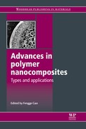
Gojny et al.10 investigated the interlaminar shear strength of nano-reinforced FRPs and described an efficient technique (mini-calendering) for dispersing carbon-based nanoparticles in epoxy resins. The application of a mini-calender to disperse carbon nanotubes (and carbon black) proved to be an efficient approach for reaching a good state of dispersion and enabled the manufacture of high volumes of nanocomposites. The resulting nanotube/epoxy composites exhibit a significant increase in fracture toughness as well as an enhancement in stiffness even with low nanotube content. Gojny et al.11 also investigated the influence of CNTs on the interlaminar shear strength of a glass-fibre-reinforced polymer (GFRP) composite. They reported an increase of + 19% in interlaminar shear strength with a weight fraction as low as 0.3 wt% of amino-functionalized doublewall CNTs (DWCNT-NH2) in the epoxy matrix, Fig. 15.1.
15.1 Interlaminar shear strength (ILSS) of (nano-reinforced) GFRPs: epoxy (EP), carbon black (CB) and double-wall carbon nanotubes (DWCNT).11
It has been claimed that the nanometre size of the particles means they can be used as modifiers in fibre-reinforced polymers. Composites have been produced via the resin-transfer-moulding (RTM) process and the particles were not filtered by the glass-fibre bundles. A follow-up review by the same research team reported that the interlaminar shear strength of the nanoparticle-modified GFRP was significantly improved (+ 16%) whilst adding only 0.3 wt% of CNTs.12 The interlaminar toughness (GIc and GIIc) was not affected in a comparable manner. The laminates containing CNTs exhibited a relatively high electrical conductivity at very low filler content.
Zhao et al.13 fabricated CNTs and continuous carbon-fibre (T300) reinforced unidirectional epoxy-resin matrix composites. They prepared CNTs by catalytic decomposition of benzene using the floating transition method at 1100–1200 °C. Benzene was used as a carbon source and ferrocene as a catalyst with thiophene. The CNTs used were straight with a diameter of 20–50 nm, internal diameter of 10–30 nm and length of 50–1000 μm. The volume fraction of continuous carbon fibre (first filler) in the composites without second filler (CNT) was 60%. The flexural strength of the composites reached a maximum value of 1780 MPa when the weight per cent of CNT in the epoxy-resin matrix was only 3%. The study concluded that the flexural strength and modulus of the composites increased at first and then decreased with an increase of the CNT content in the epoxy-resin matrix.
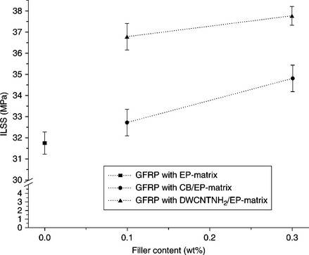
Hsiao et al.14 and Meguid and Sun15 investigated the tensile and shear strength of nanotube-reinforced composite interfaces by single lap shear testing. They observed a significant increase in the interfacial shear strength for epoxies with contents between 1 and 5 wt% of multi-walled nanotubes (MWNTs) when compared with the neat epoxy matrix. In particular, instead of processing and characterizing CNT/ polymer composites, Hsiao et al.14 explored the potential of using CNTs to reinforce the adhesives joining two composite structures. In the study, different weight fractions of MWNT were dispersed in epoxy to produce toughened adhesives. The reinforced adhesives were used to bond the graphite fibre/epoxy composite adherends. This experimental study showed that adding 5 wt% MWNT to an epoxy adhesive effectively transferred the shear load from the adhesive to the graphite fibre system in the composite laminates and improved the average shear strength of the adhesion by 46% (± 6%). A significant enhancement of the bonding performance was observed as the weight fraction of CNTs was increased. As shown in Fig. 15.2 (left), the 5 wt% MWNT effectively transferred the load to the graphite fibres in the adherends and the resulting failure was in the graphite fibre system. On the other hand, for epoxy adhesives containing no MWNTs (see Fig. 15.2 (right)), failure occurred at the epoxy along the bonding interface and no significant fractures of the graphite fibre were observed. Despite the promising results, the researchers concurred that further experiments involving increasing MWNT weight fractions and more detailed scanning electron microscopy (SEM) observations are required in order to understand and model the role of MWNTs in enhancing adhesion.
15.2 Left: SEM image of a fracture surface of the bonding area of 5 wt% MCNT + epoxy; failure of the graphite fibre of the adherends was observed. Right: SEM image of a fracture surface of the bonding area of the epoxy-only case; failure occurred at the epoxy surface of the adherends and no significant graphite fibre fracture was observed.14
Various studies can be found on the incorporation of CNFs in polymeric matrices giving the final mechanical and electrical properties of these materials. As in all cases where nano-sized fillers are involved, the development of highperformance CNF/polymer composites requires a homogeneous dispersion of CNFs in the polymeric matrix because it is crucial to the composite’s performance. Early studies by Hussain16 reported that matrix reinforcement with nanowhiskers can damage the fibres in composite materials. As such, he incorporated microscale and nanoscale Al2O3 particles in filament-wound carbon-fibre/epoxy composites. He observed an increase in modulus, flexural strength, interlaminar shear strength and fracture toughness when the matrix was filled at 10 vol% with alumina particles (25 nm diameter). This effect stemmed largely from the large surface area of the filler and the ability of the particles to mechanically interlock with the fibres. Hybrid reinforced composites consisting of two or more different types of reinforcing fibres have also been studied in polymer matrix composite systems. It has also been reported that hybridization by incorporating whiskers into the matrix causes fibre damage resulting in a decrease in ultimate strength. However, the work claimed that the incorporation of a rigid spherical filler, especially a fine or nano-sized filler, did not cause serious damage to the fibre surfaces.
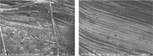
Mahfuz et al.17 studied the tensile response of carbon-nanoparticle/whisker- reinforced composites and observed a 15–17% improvement in tensile strength and modulus. Iwahori and Ishikawa18 reported compressive strength improvements in carbon-fibre-reinforced polymer (CFRP) composite laminates by using cup-stacked carbon nanofibres (CSCNFs) dispersed in epoxy as three-phase composites. Iwahori et al.19 went a step further and employed two types of CSCNF with different aspect ratios, i.e. with a fibre length of 500 nm to 1 μm (AR10) and a fibre length of 2.5 to 10.0 μm (AR50), respectively. These two types of CSCNF were dispersed into the epoxy resin. At the first trial stage, a manual fabrication process of the composite plates by impregnation of the diluted compound with the same epoxy into a dry carbon-fibre fabric was employed, followed by hot-press curing. Compression strength improvements of around 15% were attained in the three-phase composites, in comparison with the control case with no CSCNFs. Encouraged by the promising mechanical properties, they also manufactured cup- stacked carbon nanotubes (CSCNTs) dispersed in CFRP fabric to obtain more stable mechanical properties than manual fabrication processes. Figure 15.3 shows typical CSCNTs manufactured. They evaluated the mechanical properties of the CSCNT-dispersed CFRP and found an improvement in stiffness and strength (e.g. compressive strength) in two-phase and three-phase nanocomposite materials. The researchers accepted that another key issue in pre-impregnated composite fibre (prepreg) development is the optimization of the aspect ratio of CSCNFs.
15.3 Left: Schematic view of cup-stacked carbon nanotube.19 Right: Typical transmission electron micrograph.20
Although the details of this process were not disclosed, it is noteworthy that it has one advantage for good dispersion because of the multiple number of edges of graphene sheets on the CSCNF surface. Such edges may help to increase interaction between the CSCNF and polymer. A good dispersion of the CSCNF was suggested in the micrographs for the three-phase composites made through the prepreg route. There was a large improvement of the compression strength for these three-phase composites made using the prepreg method compared with manually impregnated samples. For a T-700 CF UD prepreg sample, the compression strength in the fibre direction improved by 25% in comparison with the control sample (no CSNF). However, the elastic modulus during compression of this composite was not affected as naturally expected. More recently, Yokozeki et al.20 investigated the damage accumulation that occurred in carbon-fibre- reinforced nanocomposite laminates under tensile loading. The nanocomposite laminates used in the study were manufactured from prepregs consisting of traditional carbon fibres and epoxy resin filled with CSCNTs. The thermomechanical properties of the unidirectional carbon-fibre-reinforced nanocomposite laminates were evaluated, and cross-ply laminates were subjected to tension tests to observe the damage accumulation of matrix cracks. As shown in Fig. 15.4, the number of matrix cracks in CSCNT-dispersed CFRP is much less than in conventional CFRP. A clear retardation of matrix-crack accumulation in CSCNT-dispersed CFRP laminates (both 5 wt% and 12 wt%) compared with laminates without CSCNT can be observed. Fracture toughness associated with matrix cracking was evaluated based on an analytical model using the experimental results. It was suggested that the dispersion of CSCNTs resulted in fracture-toughness improvement and residual thermal strain decrease, which was considered to cause the retardation of matrix-crack formation.
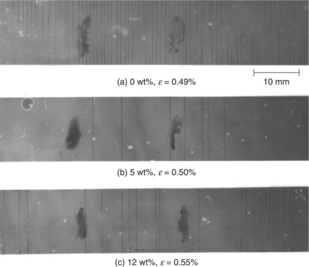
15.4 (a-c) Comparison of the accumulation of matrix cracks in cross-ply laminates; ε is the applied strain.20
In the work of Wichmann et al.,12 different nanoparticles, such as fumed silica and carbon black, were used to optimize the epoxy matrix system of a glass-fibre- reinforced composite. Their nanometre size enabled their application as particle reinforcement in FRPs produced by a modified RTM, without being filtered by the glass-fibre bundles. Figure 15.5 is a schematic of a modified-RTM device. An electrical field was applied during curing in order to enhance the orientation of the nanofillers in the z-direction. The interlaminar shear strengths of the nanoparticle- modified composites were significantly improved (+ 16%) and an increase in fracture toughness of 42% was observed by adding only 0.3 wt% of CNTs. The interlaminar toughness was not affected in a comparable manner. Only the fumedsilica nanocomposites exhibited a negligible decrease in Young’s modulus. However, with 0.5 vol% of epoxy-functionalized fumed-silica nanoparticles, KIc increased by 55%. The laminates containing CNTs exhibited relatively high electrical conductivity at very low filler content, which suggests functional properties such as stress–strain monitoring and damage detection.
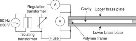
15.5 Modified RTM-device. The electrical field is applied between the brass plates (z-direction).12
It should be acknowledged that traditional fibre-reinforced composite materials with excellent in-plane properties perform poorly when out-of-plane through-thickness properties are important. Composite architectures with fibres designed orthogonal to the two-dimensional (2D) layout in traditional composites could alleviate this weakness in the transverse direction, but efforts so far have only had limited success. Nevertheless, the combination of a nanotube-modified matrix together with conventional fibre reinforcements (e.g. carbon, glass or aramid fibres) could lead to a new generation of multifunctional materials. Besides electrical conductivity, which can be induced by the carbon nanoparticles, an additional z-reinforcement can be expected. The fibre orientation in structural components is usually in plane (x- and y-directions), leading to fibre-dominated material properties in these directions, whereas the z-direction remains matrix dominated. With regard to the nanometric size, carbon nanoparticles allow an infiltration between the microscale fibres. The use of CNTs at the reinforcing phase should improve the matrix properties, especially in the z-direction, which is equivalent to improving the interlaminar properties.
One of the applications of CNT-reinforced polymers for filament-wound CFRP was demonstrated by Spindler-Ranta and Bakis.21 An amount of 1 wt% singlewalled nanotubes (SWNTs) was added to an epoxy polymer matrix. However, this study concluded that SWNTs did not produce any noticeable effect on the CNT-reinforced composites and filament-wound CFRP rings. In contrast, Veedu et al.22 reported significant improvements in the interlaminar fracture toughness, hardness, delamination resistance, in-plane mechanical properties, damping, thermoelastic behaviour and thermal and electrical conductivities. They presented an approach to three-dimensional(3D) through-the-thickness reinforcement, without altering the 2D stack design, using interlaminar CNT forests, which provide enhanced multifunctional properties along the thickness direction. The CNT forests allowed the fastening of adjacent plies in the 3D composite. They grew MWNTs on the surface of micro-fi bre fabric cloth layouts, normal to the fibre lengths, resulting in a 3D effect between plies under loading. These nanotube- coated fabric cloths served as building blocks for multilayered 3D composites, with the nanotube forests providing interlaminar strength and toughness under various loading conditions.
15.2.2 Laminated layered silicates/epoxy FRP nanocomposites
In the early 1990s, the Toyota research group synthesized polyamide-6-based clay nanocomposites that demonstrated the first use of nanoclays as a reinforcement for polymer systems.23 They concluded that nanoclays not only influenced the crystallization process, but that they were also responsible for morphological changes. Recognizing these benefits, many researchers, using a variety of clays and polymeric matrices, have produced nanocomposites with improved properties.24
Haque et al.,25 using a similar manufacturing process (i.e. vacuum-assisted resin infusion moulding or VARIM), showed a large improvement of the mechanical properties of their S2-glass-fibre laminates with a very low layered- silicate content. They showed that, by dispersing 1 wt% nanosilicates, S2-glass/ epoxy-clay nanocomposites exhibited an improvement of 44%, 24% and 23% in interlaminar shear strength, flexural strength and fracture toughness respectively. Similarly, the nanocomposites exhibit approximately 26 °C higher decomposition temperatures than conventional composites. The increased properties at low loading were attributed to several factors:
• enhanced matrix properties due to lamellar structures,
• synergistic interaction between the matrix, clay and fibres,
The clays were also presumed to decrease the mismatch in the coefficient of thermal expansion, significantly reducing residual stresses and leading to higher quality laminates. Increased interfacial bonding, matrix agglomeration and coarse morphology were observed on the fractured surface of the low loading nanocomposites. The degradation of these properties at higher clay loadings was believed to be caused by phase-separated structures and also by defects in the cross-linked structures. However, the authors acknowledged that further work was necessary in order to produce clay-epoxy nanocomposites with a fully exfoliated structure.
Similarly, Chowdhury et al.26 employed the VARIM process to manufacture woven carbon-fibre-reinforced polymer matrix composites. They investigated the effects of nanoclay particles on the flexural and thermal properties. Different weight percentages of a surface-modified montmorillonite mineral were dispersed in SC-15 epoxy using sonication. The nanophased epoxy was then used to manufacture 6000 fibre tow-plain weave carbon/epoxy nanocomposites using the VARIM technique. Flexural test results of thermally post-cured samples indicated a maximum improvement in strength and modulus of about 14% and 9%, respectively. Dynamic mechanical analyses (DMA) of the thermally post-cured samples showed a maximum improvement in the storage modulus of about 52% and an increase in the glass transition temperature of about 13 °C. In terms of mechanical and thermal properties, 2 wt% nanoclay seems to be an optimum loading for carbon/SC-15 epoxy composites. Microstructural studies revealed that nanoclay promotes good adhesion of the fibre and matrix, thereby increasing the mechanical properties.
Lin et al.21 successfully prepared layered silicate/glass-fibre/epoxy hybrid composites using a vacuum-assisted resin transfer moulding (VARTM) process. Figure 15.6 shows a schematic of the experimental set-up for the closed-mould VARTM process. They selected clay and short-length glass fibres to reinforce an epoxy resin. To study the effects of fibre direction on clay distribution in the hybrid composites, unidirectional glass fibres were placed in two directions: parallel and perpendicular to the resin flow direction. The intercalation behaviour of the clay and the morphology of the composites were investigated using X-ray diffraction (XRD) and transmission electron microscopy (TEM). The complementary use of XRD and TEM revealed an intercalated clay structure in the composites. Dispersion of the clay in the composites was also observed using SEM. The clays were dispersed both between the bundles of the glass fibres and within the interstices of the fibre filaments. The mechanical properties of the ternary composites were also evaluated. The results indicated that introducing a small amount of organoclay to glass-fibre/epoxy composites enhanced their mechanical and thermal properties, confirming the synergistic effects of glass fibres and clays in the composites.
15.6 Preparation of nanoclay/glass-fibre/epoxy composites using VARTM.27
Aktas et al.28 developed a novel approach for the characterization of nanoclay dispersion in polymeric composites using electron microprobe analysis (EMPA). Dispersion analysis was performed on three sets of centre-gated discs fabricated by RTM. The first set was neat epoxy polymer without reinforcement, whereas the second set comprised 17 vol% randomly oriented chopped glass-fibre preforms. The final set, in addition to the glass-fibre reinforcement, contained 1.7 wt% Cloisite 25A nanoclay. After curing, a sample along the radius of a nanoclay- reinforced disc was analysed with an electron microprobe analyser. The scanning electron micrographs indicated that the nanoclay exists in clusters of various sizes ranging from over 10 μm down to submicrometre scale. Nanoclay clusters larger than 1.5 μm were analysed by digital image processing of scanning electron micrographs taken along the sample radius. The dispersion of nanoclay clusters smaller than 1.5 μm was quantified by compositional analysis via wavelength dispersive spectrometry (WDS). The distribution of nanoclay clusters larger than 1.5 μm was found to be approximately constant along the radius with an average value of 1.4% by volume. Similarly, nanoclay clusters smaller than 1.5 μm were found to be distributed evenly with an average value of 0.41 wt%. In addition, the glass transition temperature improved by 11% with the addition of nanoclay.
Gilbert et al.29, 30 and Timmerman et al.31 demonstrated that fracture toughness and mechanical properties are increased by the incorporation of metal and inorganic particles. They developed La PolynanoGrESS (layered polynanomeric graphite epoxy scaled system), which utilizes the nanoparticle effect in an epoxy matrix and scales to a continuous carbon-fibre-reinforced composite system. Typically, Timmerman et al.31 modified the matrices of carbon-fibre/epoxy composites with layered inorganic clays and a traditional filler to determine the effects of particle reinforcement, both microscale and nanoscale, based on the response of these materials to cryogenic cycling. The mechanical properties of the laminates studied were not significantly altered through nanoclay modification of the matrix. The incorporation of a nanoclay reinforcement at a suitable concentration resulted in laminates with microcrack densities lower in response to cryogenic cycling than those seen in unmodified or macro-reinforced materials. Lower nanoclay concentrations resulted in a relatively insignificant reduction in microcracking and higher concentrations displayed a traditional filler effect.
Brunner et al.32 extended the work of Timmerman et al., using epoxy with a relatively small amount of nano-sized filler as a matrix in fibre-reinforced laminates. They focused on investigating whether a nano-modified epoxy matrix yields improved delamination resistance in a fibre-reinforced laminate compared with a laminate with neat epoxy as the matrix material. To start with, neat and nano-modified epoxy specimens without fibre reinforcement were prepared for a comparison of the fracture toughness of the matrix material itself. Additional properties of the neat and nano-modified epoxy were also determined (partly taken from Timmerman et al.31) and compared. The study reported an improvement in fracture toughness up to about 50% and energy release rates increased by about 20% with the addition of 10 wt% of organosilicate clay.
Several other studies have described property enrichment due to the addition of nanoclay to composite matrices. For instance, Schmidt,33 Mark34 and Hussain et al.16 demonstrated the technology of dispersing Al2O3 particles in a matrix and investigated their effect on the mechanical properties of CFRP. The incorporation of filler particles resulted in higher fracture toughness by significantly improving the toughness of the matrix and crack deviation. Studies on carbon/SiC-epoxy nanocomposites reported a 20-30% improvement in mechanical properties.35 Mohan et al36 evaluated the tensile performance of S2-glass/epoxy composites dispersed with alumina nanoparticles up to 1.5% weight fraction and found an increase of 12% in tensile modulus and 8% in tensile strength. Kornmann et al.37 successfully synthesized epoxy-layered silicate nanocomposites based on diglycidyl ether of bisphenol A and an anhydride-curing agent. A manufacturing process using hand lay-up, vacuum bagging and hot pressing was also developed to produce glass-fibre-reinforced laminates with this nanocomposite matrix. Transmission electron microscopy indicated that silicate layers dispersed in the epoxy matrix have long-range order with an interlamellar spacing of about 9 nm. X-ray diffraction analysis confirmed this nanostructure both in the nanocomposites and in a fibre-reinforced composite based on the same matrix. Scanning electron micrographs of the laminate with a nanocomposite matrix showed that nanolayers stacked at the surface of the glass fibre, thus possibly improving the interfacial properties of the fibres. Flexural testing of the laminates showed that the nanolayers improved the modulus and the strength, by 6% and 27% respectively. Dynamic mechanical analyses ofthe epoxy and nanocomposite plates and their corresponding laminates showed a systematic glass transition temperature decrease of the nanocomposite-based materials. This, the researchers suggested, explained the larger water uptake observed at 50 °C in the plate and the laminate based on a nanocomposite matrix compared with those based on the pristine epoxy.
Karaki et al.38 incorporated layered clay, alumina and titanium dioxide into an epoxy matrix and fabricated continuous carbon-fibre-reinforced polynanomeric matrices to study tension-tension fatigue behaviour. They found that the number of microcracks in each layer depended on the type of particles and their concentration. Wang et al.39 demonstrated that the exfoliated clay with only 2.5 wt% in epoxy showed a significant improvement in fracture toughness and concluded that an increase in the number of microcracks and the fractured surface due to crack deflection resulted in the toughness increase. Siddiqui et al.40 investigated the mechanical properties of nanoclay-dispersed CFRP, and showed that the interlaminar fracture toughness is higher than that of conventional CFRP. Ragosta et al.41 showed that critical stress intensity factors of epoxy/silica nanocomposites increased with an increase of silica content. Work by Seferis and co-workers42 incorporated nano-sized alumina structures in the matrix and interlayer regions of prepreg-based carbon-fibre/epoxy composites. Subramaniyan et al.43 observed that the addition of 5 wt% of nanoclay increased the elastic modulus of epoxy resin under compression by 20% and that the compressive strength of glass-fibre composites with nanoclay when made by the wet lay-up technique increased by 20-25%. Subramaniyan and Sun44 showed that polymers can be toughened significantly using a relatively small amount of nanoclay particles based on three-point bending tests of edge-notched specimens with sharp crack tips. A parallel study by the same authors,45 reported that the compressive strength of unidirectional GFRP with nanoclays increased compared with conventional GFRP.
Hackman and Hollaway46 studied potential applications of clay nanocomposite materials in civil engineering structures. They concluded that there is the possibility to increase the service life of materials subjected to aggressive environments because of the increased durability of glass-fibre and carbon-fibre composites. Liu et al.47 demonstrated the improvement of fracture toughness and the reduction of water diffusivity of epoxy/nanoclay composites. Ogasawara et al.48 investigated the helium gas permeability of silicate-clay (montmorillonite) particle/epoxy nanocomposites. They reported that the incorporation of increasing amounts of montmorillonite particles reduced helium gas permeability. With an increase of montmorillonite loading, gas diffusivity decreased while gas solubility increased. Helium diffusion was found to be in agreement with numerical results based on the Hatta-Taya-Eshelby theory.49’50 They revealed that the dispersion of nanoscale platelets in a polymer is effective in improving the gas barrier property. The study appreciated the fact that surface-modified clays are amenable for making organic/clay nanocomposites because of the weak bonding force between the layers of montmorillonite.,48 In the study, a typical less viscous epoxy of Epikote 807 base resin was used for better dispersion. It was shown that a loading of the nanoclay of about 4 vol% (about 6 wt%) reduced the diffusion coefficient to 1/10, and that theoretical predictions based on an aspect ratio of 0.001 agreed well with the experimental results.
15.2.3 Polyamide FRP nanocomposites
Electrospun nanocomposite fibres have great potential in applications where both a high surface-to-volume ratio and strong mechanical properties are required, such as high-performance filters and fibre-reinforcement materials. Since the mechanical properties of fibres generally improve substantially by decreasing fibre diameter, there is considerable interest in the development of continuous electrospun polymer nanofibres. In this respect, Lincoln et al.51 reported that the degree of crystallinity of polyamide-6 (PA-6) annealed at 205 °C increased substantially with the addition of montmorillonite (MMT). This implied that the silicate layers could act as nucleating agents or growth accelerators. In contrast, a study by Fong et al.52 showed a very similar overall degree of crystallinity for electrospun PA-6 and PA-6/Cloisite-30B nanocomposite fibres containing 7.5 wt% of organically modified MMT (OMMT) layers.
Fornes and Paul53 found that OMMT layers could serve as nucleating agents at 3% concentration in PA-6/OMMT nanocomposites but retarded the crystallization of PA-6 at a higher concentration of around 7%. In addition, the differences in the molecular weight (MW) of PA-6 and the solvent used for electrospinning were also expected to have different effects on the mobility of PA-6 molecular chains and the interactions between the PA-6 chains and OMMT layers, which may also affect the crystallization behaviour of PA-6 molecules during electrospinning. Li et al.54 manufactured PA-6 fibres and nanocomposite fibres with an average diameter of around 100 nm by electrospinning using 88% aqueous formic acid as the solvent. The addition of OMMT layers in a PA-6 solution increased the solution viscosity significantly and changed the resulting fibre morphology and sizes. TEM images of the nanocomposite fibres and ultra-thin fibre sections and wide-angle X-ray diffraction results showed that the OMMT layers were well exfoliated inside the nanocomposite fibres and oriented along the fibre axial direction. The degree of crystallinity and crystallite size both increased for the nanocomposite fibres and, more significantly, for the fibres electrospun from the 15% nanocomposite solution, which exhibited the finest average fibre size. As a result, the tensile properties of electrospun nanocomposites were greatly improved. Young’s modulus and the ultimate strength of electrospun nanocomposite fibrous mats improved to 70% and 30%, respectively, compared with PA-6 electrospun mats. However, the ultimate strength of nanocomposite fibrous mats electrospun from 20% nanocomposite solution decreased by about 20% due to their larger fibres. Young’s modulus of PA-6 electrospun single fibres with a diameter around 80 nm was almost double the highest value reported for conventional PA-6 fibres and could be improved by about 100% for electrospun nanocomposite single fibres of similar diameters.
Liang et al.55 described a fibre that consisted of a nano-Fe2O3-particle/PA-6 nanocomposite. The thermal stability of the composite material was enhanced by about 16 °C (from 440 °C to 456 °C) by the addition of Fe2O3 nanoparticles with 15.0% content (part per hundred parts of resin). The Fe2O3-reinforced materials processed by melt spinning displayed an improved tensile modulus compared with similarly processed pure PA-6; the improvements in tensile strength and modulus were about 21% and 112%, respectively. Moreover, this fibre absorbed ultraviolet and visible light.
In another interesting study,56 a range of polymer matrices, including polyvinyl alcohol, poly (9-vinyl carbazole) and polyamide, were examined. To compare production methods, polymer composite films and fibres were produced. It was found that, by adding various mass fractions of nanofillers, both Young’s modulus and hardness increased significantly for both films and fibres. In addition, thermal behaviour was seen to be strongly dependent on the nanofillers added to the polymer matrices. Wu et al.57 prepared carbon-fibre-reinforced and glass-fibre- reinforced PA-6 and PA-6/clay nanocomposites. The fabrication method involved first mechanically mixing PA-6 and PA-6/clay with E-glass short fibres (6-mm long) and carbon fibres (6-mm long), separately. A twin-screw extruder at a rotational speed of 20 rpm extruded the fibres. The temperature profiles of the barrel were 190–210–230–220 °C from the hopper to the die. The extrudate was pelletized, dried and injection moulded into standard test samples for mechanical property tests. The injection-moulding temperature and pressure were 230 °C and 13.5 MPa, respectively. The research found that the tensile strength of PA-6/clay containing 30 wt% glass fibres was 11% higher than that of PA-6 containing 30 wt% glass fibre, while the tensile modulus of the nanocomposite increased by 42%. The flexural strength and flexural modulus of neat PA-6/clay were found to be similar to PA-6 reinforced with 20 wt% glass fibres. It was concluded that the effect of nanoscale clay on toughness was more significant than that of the fibre. The heat distortion temperatures of the PA-6/clay and PA-6 were 112 °C and 62 °C, respectively. Consequently, the heat distortion temperature of the fibre- reinforced PA-6/clay system was almost 20 °C higher than for the fibre-reinforced PA-6 system. The notched Izod impact strength of the composites decreased with the addition of the fibre. Scanning electron microphotographs showed that the wet-out of glass fibre was better than carbon fibre. The study concluded that the mechanical and thermal properties of the PA-6/clay nanocomposites were superior to those of the PA-6 composite in terms of heat distortion temperature, tensile and flexural strength and modulus without sacrificing their impact strength. This was attributed to nanoscale effects and the strong interaction force that existed between the PA-6 matrix and the clay interface.
Regarding short fibres, Akkapeddi58 prepared PA-6 nanocomposites using chopped glass fibres. A typical experiment used a commercial grade PA-6 with a molecular weight of 30 kg/mol and specially designed functional organo- quaternary ammonium-clay complexes (organoclays) based on MMT or hectorite- type clays. Freshly dried PA-6 (moisture < 0.05%) was blended with 3–5 wt% of a selected organoclay powder and extruded at 260 °C in a single step under high shear mixing conditions. Alternatively, the organoclay was master-batched first into PA-6 (at 25 wt% loading and then re-extruded in a second step with more PA-6 to dilute the clay content to < 5 wt%). Conventional chopped glass fibre, 10 μm in diameter and about 3 mm in length, was then added as an optional reinforcement through a downstream feed port at zone 6 of a twin-screw extruder. The glass fibre was compounded with the molten, premixed PA-6 nanocomposite either as a one-step extrusion process or in a second extrusion step. The extrudate was quenched in a water bath and pelletized. The pellets were dried under vacuum at 85 °C and injection moulded into standard ASTM test specimens. As shown in Fig. 15.7, significant improvements in modulus were achievable in both the dry and the moisture-conditioned states for PA-6 nanocomposites compared with standard PA-6, at any given level of glass-fibre reinforcement. In particular, a small amount (3–4 wt%) of nanoscale dispersed layered silicate was capable of replacing up to 40 wt% of a standard mineral filler or 10–15 wt% of glass fibre to give equivalent stiffness at a lower density. In addition, improved moisture resistance, permeation barrier and fast crystallization/mould cycle time contribute to the usefulness of such composites.
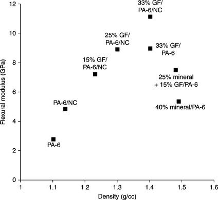
15.7 Modulus vs. density of glass fibre (GF) for PA-6/nanoclay (PA-6/NC) and PA-6 moulding resins.58
Vlasveld et al.59 developed a three-phase thermoplastic composite, consisting of a main reinforcing phase of woven glass or carbon fibres and a PA-6 nanocomposite matrix. The nanocomposites used in this research had moduli that were much higher than unfilled PA-6, including above Tg and moisture-conditioned samples. Flexural tests on commercial PA-6 fibre composites showed a decrease of flexural strength on increasing temperature. The researchers claimed that the strength of the glass-fibre composites was increased by more than 40% at elevated temperatures and the temperature range for a given minimum strength was increased by 40–50 °C. The carbon-fibre composites also showed significant improvements at elevated temperatures, although not at room temperature. Based on flexural tests on PA-6-based glass and carbon-fibre composites over a large temperature range up to near the melting point, it became clear that for these fibre composites it is important to have a reasonably high matrix modulus. Both glass and carbon composites were very sensitive to a decrease of the matrix modulus below values around 1 GPa. At higher moduli, the carbon-fibre composites were more sensitive to the matrix modulus than glass-fibre composites. The modulus of unfilled PA-6 decreased below the (arbitrary) 1 GPa level just above Tg. It is noteworthy that the nanocomposites used in this research had moduli that were much higher and stayed above the 1 GPa level up to 160 °C, which was more than 80 °C higher than for unfilled PA-6. The nanocomposites also showed much higher moduli in moisture-conditioned samples. Even in moisture-conditioned samples tested at 80 °C, the modulus was much higher than for the dry unfilled PA-6, which again was well above 1 GPa. DMA measurements indicated that the nanocomposites did not show a change of Tg and that the reduction of the modulus on absorption of moisture was due to the Tg decrease.
Vlasveld et al.60 investigated fibre-matrix adhesion in glass-fibre-reinforced PA-6 silicate nanocomposites. The main reinforcing phase consisted of continuous E-glass fibres, whereas the PA-6-based matrix was a nanocomposite reinforced with platelets of exfoliated layered silicate. Two different types of nanocomposite were used with different degrees of exfoliation of the silicate layers: one with unmodified silicate and one with an organically modified silicate. They developed nanocomposite laminates by the sol–gel and modified-diaphragm methods. The preparation of the PA-6 nanocomposites consisted of melt-compounding Akulon® K122D with Somasif® MEE and Somasif® ME-100 by means of a co-rotating twin-screw extruder at 240 °C. For the Somasif® MEE nanocomposite materials, an 11 wt% MEE master batch was initially compounded. To obtain the various concentrations of the MEE nanocomposite, the master batch was extruded for a second time without dilution for the 11 wt% nanocomposite, or diluted with Akulon® K122D to concentrations of 6.1 and 2.7 wt%. The 2.5 wt% Somasif® ME-100 nanocomposite material was produced by diluting a 10% ME-100 master batch with Akulon® K122D in the extruder. (All percentages are weight percentages of silicate measured with a thermogravimetric analyser (TGA) after heating for 40 min at 800 °C in air.) Two demands in the preparation of the single- fibre fragmentation specimens had to be met: the fibre had to lie straight in the centre of the specimen and the matrix material of the specimen had to be thin enough to be transparent, since the fibre fragments were examined and measured using an optical microscope. A Fontijne hot-plate press heated to 240 °C was used to produce the films for the single-fibre fragmentation test specimen. Single fibres were carefully extracted from a fibre bundle and placed at a distance of approximately 2 cm apart parallel to each other between the PA or nanocomposite films. The hot-plate press was used to melt the polymer films and a pressure of 0.8 N/mm2 was applied for 30 s to provide the necessary bonding with the fibre.
After cooling between cold metal plates, tensile test specimens were prepared. It was observed that the ultimate strength and stiffness increased by adding 1% SiO2 nanoparticles, while little improvement in fatigue behaviour was found. It was concluded that the failure mechanism was by interfacial de-bonding and that both the addition of nanoparticles and moisture conditioning had a negative effect on the bonding between the matrix and the glass fibres. In addition, the researchers noted that, in the composites formed, adhesion between the nanocomposites and the carbon fibres (Fig. 15.8) was probably worse than between the unfilled PA-6 and the matrix, reducing the potentially positive influence of the increased matrix modulus.
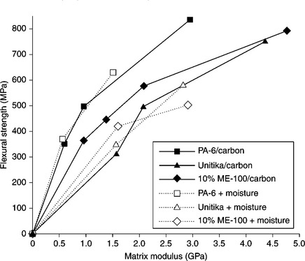
15.8 Flexural strength of carbon-fibre composites with PA-6, a commercially available PA-6 nanocomposite (Unitika M1030D from Unitika) and a nanocomposite matrix as a function of the matrix modulus (dry and moisture conditioned).60
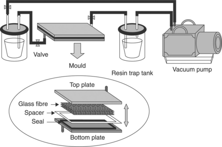
An assessment of reactively processed anionic polyamide-6 (APA-6) for use as a matrix material in fibre composites was conducted by van Rijswijk et al.61 They also compared it with melt-processed PA-6 and PA-6 nanocomposites. A specially designed lab-scale mixing unit was used to prepare two liquid material formulations at 110 °C under a nitrogen atmosphere: a monomer/activator mixture in tank A and a monomer/initiator mixture in tank B, as shown in Fig. 15.9. After individually degassing both tanks (15 min at 100 mbar), the two material feeds were mixed using a heated (110 °C) static mixer and dispensed (1:1 ratio) into a heated (110 °C) buffer vessel with nitrogen protective environment. A stainless-steel infusion mould was used together with a 3-mm-thick stainless-steel cover plate (not shown) to manufacture neat APA-6 panels (250×250×2 mm). Homogeneous heating of the mould was obtained by placing it in a vertically positioned hot flat platen press. Silicon tubes connected the resin inlet of the mould to the buffer vessel and the resin outlet to a vacuum pump. Infusion from bottom to top was necessary to prevent entrapment of air. A pressure-control system was used to precisely set the infusion and curing pressures (absolute pressure in the mould cavity). Loss of control over the pressure in the mould cavity due to solidification of resin in the unheated outlet tube had to be prevented. To avoid this, a buffer cavity was machined in the mould near the outlet to slow down the infusion, hence giving ample time to stop the resin flow before it was able to exit the mould. For each infusion pressure, the infusion time to reach the buffer cavity was determined visually because the steel cover plate had been replaced by a glass one. Additionally, a resin trap and a cold trap were placed directly after the mould to protect the vacuum pump.
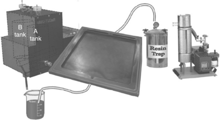
15.9 Infusion equipment. From left to right: Mini mixing unit (MMU-TU Delft), resin reservoir, stainless-steel infusion mould, resin trap, cold trap and vacuum pump.61
The mechanical properties of APA-6 and HPA-6 (Akulon® K222D, low-MW injection-moulding grade hydrolytically polymerized PA-6) nanocomposites were compared with injection-moulded neat HPA-6. As expected, the HPA-6 nanocomposite had the highest modulus over the entire range of temperatures (20–160 °C) and moisture content (0–10 wt%) tested. However, APA-6 came close and had the highest maximum strength due to its characteristic crystal morphology, which was directly linked to the reactive type of processing used. This same morphology, it was claimed, also made APA-6 slightly less ductile compared with melt-processed HPA-6. Compared with the melt-processed HPA-6, APA-6 polymerized at 150 °C and the HPA-6 nanocomposite had a higher modulus at a similar temperature, or a similar modulus at a higher temperature (40–80 °C increase). It is noteworthy that such an increase in maximum-use temperature, related to the heat distortion temperature, can seriously expand the application possibilities for PA-6 and PA-6 composites. For all PAs, temperature and moisture absorption reduced the modulus and the strength and increased the maximum strain, which was directly related to the glass transition temperature. It was observed that moisture absorption reduced Tg to below the testing temperature. However, the effect of both was in essence the same. Retention of the mechanical properties of APA-6 after conditioning at 70 °C for 500 h and subsequent drying was demonstrated. Conditioning by submersing in water at the same temperature, however, resulted in a brittle material with surface cracks, as is common with most polyamides, which was caused by continued crystallization and the removal of unreacted monomer. Given the fact that submersion at elevated temperatures is usually not an environment in which PA-6 and its composites are applied, this property reduction was therefore not detrimental for the application of these materials. The overall conclusion of this comparative study into the application of polyamides as matrix materials in fibre composites was that both APA-6 and the HPA-6 nanocomposites outperformed melt-processed HPA-6 in terms of modulus and maximum strength. Therefore, the researchers concluded that both ‘improved’ PAs may be expected to enhance matrix-dominated composite properties like compressive and flexural strength, provided that a strong fibre-to-matrix interphase is obtained.
Another comparative study was conducted by Sandler et al.62 on melt-spun PA-12 fibres reinforced with carbon nanotubes and nanofibres. A range of MWNTs and carbon nanofibres were mixed with a PA-12 matrix using a twin-screw microextruder and the resulting blends spun to produce a series of reinforced polymer fibres. The work aimed to compare the dispersion and resulting mechanical properties for nanotubes produced by the electric arc and a variety of chemical vapour deposition techniques. A high quality of dispersion was achieved for all the catalytically grown materials and the greatest improvements in stiffness were observed using aligned, substrate-grown, carbon nanotubes. The use of entangled MWNTs led to the most pronounced increase in yield stress, most likely as a result of increased constraint of the polymer matrix due to the relatively high surface area. The degree of polymer and nanofiller alignment and the morphology of the polymer matrix were assessed using X-ray diffraction and differential scanning calorimetry (DSC). The carbon nanotubes were found to act as nucleation sites under slow-cooling conditions, the effect scaling with effective surface area. Nevertheless, no significant variations in polymer morphology as a function of nanoscale-filler type and loading fraction were observed under the melt-spinning conditions applied. A simple rule-of-mixture evaluation of the nanocomposite stiffness revealed a higher effective modulus for the MWNTs compared with the carbon nanofibres, a result of improved graphitic crystallinity. In addition, this approach allowed a general comparison of the effective nanotube modulus with those of nanoclays as well as common short glass and carbon-fibre fillers in meltblended PA composites. The experimental results further highlighted the fact that the intrinsic crystalline qualities, as well as the straightness of the embedded nanotubes, were significant factors influencing reinforcement capability.
15.2.4 Poly (ether ether ketone) (PEEK) FRP nanocomposites
Jen et al.63 manufactured AS-4/PEEK APC-2 nanocomposite laminates and also studied their mechanical responses. The experimental procedures were as follows: firstly, the nanoparticles were diluted in alcohol (50 ml alcohol: 2 g SiO2) and stirred uniformly. Then, 16 plies of [0/90]4s cross-ply and [0/± 45/90]2s quasi- isotropic prepregs were cut, SiO2 solution was spread on the prepregs in a temperature-controlled box, and after evaporation of alcohol the nanoparticles were found to weigh in the range 111–148 mg/ply. The next step was to repeat the spreading for 5, 8, 10 and 15 plies, followed by consolidation of the stacked plies in a hot press to form a laminate 2 mm thick. The consolidation process is shown in Fig. 15.10.
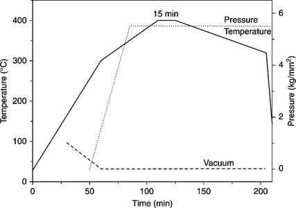
15.10 Pressure-temperature profile of the curing process of AS-4/PEEK APC-2 nanocomposites.63
Next, the laminates were cut into specimens and tested according to ASTM D3039M. The tensile tests were repeated at 50, 75, 100, 125 and 150 °C. These tests measured stress–strain, strength and stiffness and the obtained data were compared with those for the original APC-2 laminate (no SiO2 nanoparticles) and showed that the optimal content of SiO2 nanoparticles was 1% by total weight. The ultimate strength increased by about 12.48% and elastic modulus by 19.93% in quasi-isotropic nanolaminates, whilst the improvement for cross-ply nanocomposite laminates was less. At elevated temperatures the ultimate strength decreased slightly below 75 °C and the elastic modulus reduced slightly below 125 °C; however, both properties degraded highly at 150 °C (≈ Tg) for the two layups. Finally, after constant stress amplitude tension-tension (T–T) cyclic testing, it was found that both stress-cycle (S–N) curves were very close, being below 104 cycles for cross-ply laminates with or without nanoparticles, and the S–N curve of the nanolaminates was slightly reduced after 105 cycles.
Sandler et al.64 produced poly (ether ether ketone) nanocomposites containing vapour-grown carbon nanofibres using standard polymer processing techniques. Macroscopic PEEK nanocomposite master batches containing up to 15 wt% vapour-grown CNF were prepared using a Berstorff co-rotating twin-screw extruder with a length-to-diameter ratio of 33. The processing temperatures were set to about 380 °C. The strand leaving the extruder was quenched in a water bath, air dried and then regranulated followed by drying at 150 °C for 4 h. Tensile bars according to the ISO 179A standard were manufactured on an Arburg Allrounder 420 injection-moulding machine at processing temperatures of 390 °C, with the mould temperature set to 150 °C. Prior to mechanical testing, all samples were heat treated at 200 °C for 30 min followed by 4 h at 220 °C in an attempt to ensure a similar degree of crystallinity of the polymer matrix. Macroscopic tensile tests were performed at room temperature with a Zwick universal testing machine. The cross-head speed was set to 0.5 mm/min in the 0–0.25% strain range and was then increased to 10 mm/min until specimen fracture occurred. An evaluation of the mechanical composite properties revealed a linear increase in tensile stiffness and strength with nanofibre loading fractions up to 15 wt%, while matrix ductility was maintained up to 10 wt%. Electron microscopy confirmed the homogeneous dispersion and alignment of the nanofibres. An interpretation of the composite performance by short-fibre theory resulted in rather low intrinsic stiffness properties of the vapour-grown carbon nanofibre. Differential scanning calorimetry showed that an interaction between the matrix and the nanoscale filler could occur during processing. However, such changes in polymer morphology due to the presence of nanoscale filler need to be considered when evaluating the mechanical properties of such nanocomposites.
Schmidt’s investigation65 involved multifunctional inorganic–organic composite sol–gel coatings on glass surfaces. The sol–gel process allowed the fabrication of ceramic colloidal particles in the presence of organo-alkoxysilanes carrying various perfluoroalkyl groups and the synthesis of multifunctional transparent inorganic–organic composites. The report claimed that, in addition, these composites can be used as controlled-release systems or designed as graded systems. Using this approach, a coating with a very low surface free energy (with antisoiling properties) and temperature stability up to 350 °C, a controlled-release system for permanent wettability (anti-fogging) and systems containing metal colloids for optical effects were developed. Lin66 and Wang et al.67 studied the effects of wear and friction by adding SiC nanoparticles to PEEK. The latter studied the effect of the synergism between nanometre SiC and PTFE on the wear of PEEK. Fine powders of PEEK (ICI grade 450P, η = 0.62) having a diameter of approximately 100 μm were prepared. Nanometre SiC, smaller than 80 nm, was used as a filler. The PTFE powders (25 μm in diameter), nanometre SiC and PEEK were completely mixed ultrasonically and dispersed in alcohol for ~ 15 min. Then the mixture was dried at 110 °C for 6 h to remove the alcohol and moisture. Finally, the mixture was moulded into block specimens by compression moulding, in which the mixture was heated at a rate of 10 °C min− 1 to 340 °C, held there for 8 min and then cooled in the mould to 100 °C. After release from the mould, the resultant block specimens were prepared for friction and wear tests. A tribological study found that the incorporation of PTFE into PEEK filled with 3.3 vol% nanometer SiC had a detrimental effect on the tribological properties of the SiC-PTFE-PEEK composite. The morphologies of the worn surfaces and the properties of the transfer films deteriorated, while the load-carrying capacity of the SiC-PTFE-PEEK composite was also adversely affected. The researchers claimed the reason for this was due to SiFx, which formed on the original surface and the worn surface during the compression moulding and sliding friction processes, as a result of a chemical reaction between the nanometre SiC and PTFE. The chemical reaction and the formation of SiFx dominated the tribological behaviour of the SiC–PTFE–PEEK composites filled with various contents of PTFE and 3.3 vol% nanometre SiC. When the PTFE volume percentage was low then the SiFx caused friction and the wear of the SiC–PTFE–PEEK composite to rise. However, at high volume percentages the low-friction PTFE dominated the friction and wear behaviour and friction decreased as the percentage of PTFE increased. Chemical reactions and the formation of SiFx led to changes in the worn-surface morphologies and a detrimental effect on the characteristics of the transfer films.
15.2.5 Polyimide polyarylacetylene (PAA) and poly (p-phenylene benzobisoxazole) (PBO) FRP nanocomposites
Ogasawara et al.68 directed their investigations to improving the heat resistance of a relatively new phenylethynyl-terminated imide oligomer (Tri-A PI) by loading of MWNTs. They fabricated MWNT/Tri-A PI composites containing 0, 3.3, 7.7 and 14.3 wt% MWNT using a mechanical blender without any solution (dry condition) for several minutes. The volume fractions of MWNT were calculated to be 2.3, 5.4 and 10.3 vol% from the density of the MWNT (1.9 g/cm3) and the cured polyimide (1.3 g/cm3). Scanning electron micrographs showed the particle size of the imide oligomers to be in the range 0.1-10 μm, and the MWNTs were not dispersed uniformly in the mixture. The loss of aspect ratio during mechanical blending was not significant; therefore MWNTs can be used in various ways; for example, they are suitable for mechanical blending with imide oligomers. The preparation of the nanocomposite involved melt mixing of the MWNT/imide oligomer at 320 °C for 10 min on a steel plate in a hot press and then curing at 370 °C for 1 h under 0.2 MPa of pressure with a PTFE spacer (thickness 1 mm). The resulting composites containing 3.3, 7.7 and 14.3 wt% MWNT exhibited relatively good dispersion at a macroscopic scale. Tensile tests on the composites showed an increase in the elastic modulus and the yield strength, and a decrease in the failure strain. Figure 15.11 shows the effect of MWNT concentration on the Young’s modulus of the composites.
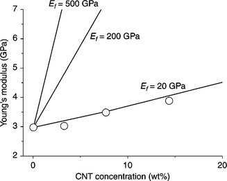
15.11 Effect of MWNT concentration on Young’s modulus of the composites.68
Dynamic mechanical analysis showed an increase in the glass transition temperature with incorporation of the carbon nanotubes. The experimental results suggested that the carbon nanotubes were acting as macroscopic cross-links and were further immobilizing the polyimide chains at elevated temperatures. As to the reason why dispersed MWNTs increased the heat distortion temperature, the researchers explained that the dispersed MWNTs impede the molecular motion in the polyimide network at elevated temperatures. The other property improvements in this material are that MWNT showed some potential for controlling electric conductivity and electromagnetic wave absorbability. Although static properties were obtained, discussions were not given and it is evident that more research is required to prove that the suggested phenomenon is a true cause of the higher glass transition temperatures.
There is increasing development in the use of polyarylacetylene (PAA) in advanced heat-resistant composites due to its outstanding heat resistance and excellent ablative properties. Fu et al.69 reviewed the advantages of PAA resin over the state-of-the-art heat-resistant resin. The main potential applications ofPAA resin are in conventional resin matrix composites with ultra-low moisture outgassing characteristics and improved dimensional stability, which are suitable for spacecraft structures, as an ablative insulator for solid rocket motors and as a precursor for carbon–carbon composites. Carbon-fibre-reinforced PAA composites (carbon fibre/PAA) undoubtedly play a very important role in all these fields. Unfortunately, the mechanical properties of the carbon-fibre/PAA material are not yet sufficiently satisfactory to replace widely used heat-resistant composites such as carbon- or graphite-reinforced phenolic resin. The mechanical properties of carbon-fibre-reinforced resin matrix composites depend on the properties of the carbon fibre and the matrix, especially on the effectiveness of the interfacial adhesion between the carbon fibre and the matrix.
PAA has a high content of benzene rings and hence a highly cross-linked network structure, which renders the material brittle. Moreover, the chemically inert characteristics of the carbon-fibre surface lead to weak interfacial adhesion between the fibres and the non-polar PAA resin. To ensure that the material can be used safely in complicated environmental conditions and to exploit the excellent heat-resistant and ablative properties more effectively, it is necessary to improve the mechanical properties of the carbon-fibre/PAA composites. This can be achieved in two ways. One method is to improve the properties of the PAA resin by structural modification or by intermixing with other resins, such as phenolic resin. The other is treatment of the carbon-fibre surface. Treatment of the carbon-fibre surface has been studied for a long time and several methods, such as heat treatment, wet chemical or electrochemical oxidation, plasma treatment, gasphase oxidation and the high-energy radiation technique have been demonstrated to be effective in the modification of the mechanical interfacial properties of composites based on polar resins such as epoxy. For instance, Zhang et al.70 treated carbon fibres by oxidation–reduction followed by coating with vinyltrimethoxysilane-silsesquioxane (VMS-SSO) to improve the interfacial mechanical properties of the carbon-fibre/PAA composites. The carbon-fibre surface-treatment process is shown in Fig. 15.12.
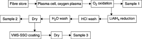
15.12 Carbon-fibre treatment process. Sample 1 is oxygen plasma oxidation, sample 2 includes LiAlH4 reduction and sample 3 includes coating with VMS-SSO.70
Polar functional groups, including carboxyl and hydroxyl, were imported onto the carbon-fibre surface after the oxygen plasma oxidation treatment. The quantity of carboxyl on the carbon-fibre surface decreased and that of hydroxyl increased after LiAlH4 reduction. The LiAlH4 reduction time was decided according to the experimental parameter in Lin.71 The VMS-SSO coating was grafted onto the carbon-fibre surface by a reaction between the hydroxyl in VMS-SSO and that on the carbon-fibre surface. The VMS-SSO coating concentrations and treatment time were decided according to Zhang et al.,72 who had optimized VMS-SSO coating treatment parameters. The investigation found that the interlaminar shear strength of the carbon-fibre/PAA composites increased by 59.3% after treatment.70 The conclusion was drawn that carbon-fibre surface oxidation-reduction followed by coating with silsesquioxane is an effective method to improve the interfacial mechanical properties of carbon-fibre/PAA composites. This kind of method could be widely used for different resin matrix composites by changing the functional groups on silsesquioxanes according to that on the resin.
Poly (p-phenylene benzobisoxazole) (PBO), a rigid-rod polymer, is characterized by high tensile strength, high stiffness and high thermal stability. Kumar et al73 found that PBO/CNT-reinforced fibres exhibited twice the energy- absorbing capability of plain PBO fibres. The nanocomposites were prepared as follows: ~ 4.3 g (0.02 mol) of 1,4-diaminoresorcinol dihydrochloride, ~ 4 g (0.02 mol) of terephthaloyl chloride and ~ 12 g of phosphoric acid (85%) were placed into a 250 ml glass flask, equipped with a mechanical stirrer and a nitrogen inlet/outlet. The resulting mixture was dehydrochlorinated under a nitrogen atmosphere at 65 °C for 16 h and subsequently at 80 °C for 4 h. At this stage, 0.234 g of purified and vacuum-dried HiPco nanotubes was added to the reaction flask. The mixture was heated to 100 °C for 16 h while stirring and then cooled to room temperature. P2O5 (8.04 g) was added to the mixture to generate poly (phosphoric acid) (77% P2O5). The mixture was stirred for 2 h at 80 °C and then cooled to room temperature. Further P2O5 (7.15 g) was then added to the mixture to bring the P2O5 concentration to 83% and the polymer concentration to 14 wt%. The mixture was heated at 160 °C for 16 h with constant stirring. Stir opalescence was observed during this step. The mixture was finally heated to 190 °C for an additional 4 h while stirring. An aliquot of the polymer solution was precipitated, washed in water and dried under vacuum at 100 °C for 24 h. An intrinsic viscosity of 14 dl/g was determined in methanesulfonic acid at 30 °C. A control polymerization of pure PBO was also carried out under the same conditions without adding SWNT. For PBO/SWNT (90/10) composition, 0.47 g of purified HiPco tubes (SWNT) was added to the mixture. The sequence of steps and polymerization conditions were the same for a PBO/SWNT (95/5) sample. The intrinsic viscosity values of PBO and PBO/SWNT (90/10) were 12 and 14 dl/g, respectively. Single-walled nanotubes were well dispersed during PBO synthesis in polyphosphoric acid (PPA). PBO/SWNT composite fibres were successfully spun from the liquid crystalline solutions using dry-jet wet spinning. The addition of 10 wt% SWNT increased PBO fibre tensile strength by about 50% and reduced shrinkage and high-temperature creep. The existence of SWNT in the spun PBO/ SWNT fibres was evidenced by a 1590 cm1 Raman peak.
15.3 Sandwich structures using polymer nanocomposites
Sandwich composites are used in a wide range of applications from aircraft, ships, ballistic vests and helmets through to racing cars and high-end sports cars. They have a wide range of useful properties, including structural stiffness, crash-energy management and heat shielding, amongst others. These structures, composed of a core of cellular material and outer composite skins, are lightweight and yet offer high resistive stiffness against traction, compressive and bending loads. These properties are utilized to produce functional structures that must sustain high stresses under normal conditions. During severe impact loads in automotive applications, for example, these structures must dissipate impact energy to protect either the rest of the structure or the vehicle’s occupants.
Research has shown that damage initiation thresholds and damage size in sandwich composites depend primarily on the properties of the core materials and facings and the relation between them. Much of the early research on sandwich composites under impact focused on a honeycomb core (Nomex, glass thermoplastic or glass-phenolic). A key problem in honeycomb sandwich construction is the low core surface area for bonding. Consequently, expanded foams (often thermoset) are now preferred for achieving reasonably high thermal tolerance, though thermoplastic foams are also used. In turn, the response of foam-core sandwich constructions to impact loading has been studied by many researchers. Accordingly, it is now well understood that the response of foam-core sandwich composites strongly depends on the density and the modulus of the foam.
A possible way of improving the properties of foam materials is through the inclusion of small amounts of nanoparticles (carbon nanotubes and nanofibres, TiO2, nanoclay, etc.) to improve the foam density and modulus properties. Up until now, montmorillonite nanoclays have been the best candidates for foam reinforcement due to ease of processing, enhanced thermal–mechanical properties, wide availability and cost. Likewise, polyurethanes (PU) are core materials of choice due to their tailorable and versatile physical properties, ease of manufacture and their low cost. The use of polyurethanes filled with nanoparticles in constructing either laminates or foams is relatively new. Moreover, the use of nanoparticles in such laminates, or foams in a sandwich composite construction, is in its infancy but has been found to be both realistic and beneficial. For instance, by using less than 5% by weight of nanoclay loadings, significant improvements in foam failure strength and energy absorption have been realized, with over a 50% increase in the impact load-carrying capacity compared with a neat foam sandwich. However, since most current research concentrates on the processing and characterization of nanophased foams and the evaluation of static properties only, dynamic material data on impact failure mechanisms and impact property relations is missing. For the application of nanophased foams in sandwich constructions for ballistic resistance, a proper understanding of their impact behaviour for both high and low-velocity impacts is required.
Therefore, by taking advantage of emerging new materials, nanophased sandwich structures have been fabricated and tested for low-velocity impact resistance, as described in the literature. In a recent development, Njuguna et al.74 fabricated and characterized a series of nanophased hybrid sandwich composites based on polyurethane/montmorillonite (PU/MMT). The polyaddition reaction of the polyol premix with 4,4′-diphenylmethane diisocyanate was applied to obtain nanophased polyurethane foams, which were then used to fabricate sandwich panels. It was found that the incorporation of MMT resulted in a higher number of PU cells with smaller dimensions and higher anisotropy index. The materials obtained exhibited improved parameters in terms of thermal insulation. Importantly, these foams can also be selectively stiffened to meet specific requirements. The results also showed that nanophased sandwich structures are capable of withstanding higher peak loads than those made of neat polyurethane foam cores when subject to low-velocity impacts, despite their lower density than neat PU foams. This is especially significant for multi-impact recurrences within the threshold loads and energies studied. A feasible application for these lightweight structures is as energy-absorbing structures or as inserts in hollow structures.
15.4 Properties and applications of polymer nanocomposites
15.4.1 Thermal stability and fire retardancy
The commercial importance of polymers has been driving the use of composites in various fields, such as aerospace, automotive, marine, infrastructure and military applications.75 Performance during use is a key feature of any composite material. Whatever the application, there is a natural concern about the durability of polymeric materials. The deterioration of these materials depends on the duration and the extent of interaction with the environment. Degradation of polymers includes all changes in chemical structure and physical properties due to external chemical or physical stresses caused by chemical reactions, involving bond scissions in the backbone of the macromolecules that lead to materials with characteristics different (usually worse) from those of the starting material (Fig. 15.13). As a consequence of degradation, the resulting smaller fragments do not contribute effectively to the mechanical properties, the article becomes brittle and the life of the material becomes limited. Thus, any polymer or its (nano)composite that is to be used in outdoor applications must be highly resistant to all environmental conditions.
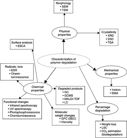
15.13 Various techniques for the characterization of polymer degradation processes and mechanisms.75 (ESCA: electron spectroscopy for chemical analysis; ESR: electron spin resonance; GC: gas chromatography; GCMS: gas chromatograph/mass spectroscopy; MALDI-TOF: matrix-assisted laser desorption ionization-time-of-flight mass spectrometry; LC: liquid chromatography; GPC (SEC): gel permeation chromatography (size exclusion chromatography); LSC: laser scanning cytometry.)
Research indicates that the modified epoxy nanocomposites possess better flame retardant properties than conventional composites. With the Kissinger method, the activation energies for the thermo-oxidative degradation of epoxy nanocomposites are less than those of the pure epoxy in the first stage of thermo-oxidative degradation. However, in the second stage of thermo-oxidative degradation the activation energies for epoxy nanocomposites are generally higher than those of the pure epoxy. For example, the main mechanism for layered silicate is barrier formation, which influences flame spread in developing fires. Several minor mechanisms are significant, but important fire properties such as flammability or fire load are hardly influenced. Hence combinations with aluminium hydroxide and organo-phosphorus flame retardants need to be evaluated. It has been shown that carbon nanotubes can surpass nanoclays as effective flame-retardant additives if the carbon-based nanoparticles (single- and multi-walled nanotubes as well as carbon nanofibres) form a jammed network structure in the polymer matrix, so that the material as a whole behaves rheologically like a gel.76
The thermal degradation of nanocomposites depends on clay loading, structure and the nature of the ambient gas. Recently Leszczyńska et al.77 reviewed the thermal stability of various polymer matrices improved by montmorillonite clay and their influencing factors in detail. For the majority of polymers, due to their hydrophobic character, the clay must be modified with a surfactant in order to make the gallery space sufficiently organophilic to permit it to interact with the polymer. In fact, several factors were found to govern the thermal stability of nanocomposite materials, such as the intrinsic thermal resistance of the polymer matrix, nanofiller content, the chemical constitution of the organic modifier and the chemical character of polar compatibilizers as well as the access of oxygen to the composite material during heating. For the surface modification of clay, the surfactant is usually described as an ‘onium’ salt, but in fact ammonium salts are most commonly used. The quaternary ammonium ion is nominally chosen to compatibilize the layered silicate with a given polymer resin. However, the molecular structure (length and number of alkyl chains and unsaturation) is also the determining factor of thermal stability of polymer/MMT nanocomposites.
A possible mechanism for the degradation of modifiers in silicates has been given by, among others, Hwu et al.78 and Leszczyńska et al.,77 and research has shown that surfactants degrade between 200 and 500 °C. The amount of surfactant lost during thermogravimetric analysis of various organoclays indicates that surfactants with multiple alkyl tails have greater thermal stability than those with a single alkyl tail. It has been proposed that organic modifiers start decomposing at a temperature of around 200 °C, and the small molecular weight organics are released first while the high-molecular weight organic species are still trapped by the organic layered silicate matrix. With increasing temperature, high-molecular organic polymer chains may exist between the interlayers until the temperature is high enough to lead to their further decomposition. The incorporation of silicate layers with a high-aspect ratio of decomposed/charred material on the clay surface acts as a carbonaceous insulator. Silicate has an excellent barrier property, which prevents permeation of various degraded gaseous products.
The addition of clay enhances performance by acting as a superior insulator and mass transport barrier to the volatile products generated during decomposition. The clay acts as a heat barrier, which could enhance the overall thermal stability of the system as well as assisting in the formation of char during thermal decomposition. In a nanocomposite, the temperature at which volatilization occurs is higher than for a microcomposite. Moreover, thermal oxidation of the polymer is strongly slowed in a nanocomposite with high-char yield, both by a physical barrier effect, enhanced by ablative reassembling of the silicate, and by a chemical catalytic action due to the silicate and the strongly acid sites created by thermal decomposition of the protonated amine silicate modifier.
Polymers that show good fire retardancy on nanocomposite formation exhibit significant intermolecular reactions, such as inter-chain aminolysis or acidolysis, radical recombination and hydrogen abstraction. For polymers that degrade through a radical pathway, the relative stability of the radical is the most important factor in predicting the effect that nanocomposite formation has on the reduction in the peak heat release rate. The more stable the radical produced by the polymer, the better the fire retardancy, as measured by the reduction in the peak heat release rate of the polymer/clay nanocomposite.
CNTs are increasingly finding applications as thermal management materials and are also being considered in potential interface and attachment techniques.79 Interfaces between materials have a significant effect on the thermal impedance of electronic systems and in practice they can be the dominant factor in achieving effective thermal transfer. The interface materials and processes in question are the methods used to join an electronic device to a thermal transfer medium (e.g. substrate, heat pipe, heat sink), including coatings and bonding techniques. In this respect, they may need to perform the tasks of attachment, stress/strain relief and thermal transfer. The simplest of all interfaces is a dry joint (two surfaces pushed together). In this case, interface thermal resistance can be significant and will depend on the surface materials: their hardness, co-planarity, roughness and the applied pressure to hold the surfaces together. To enhance heat transfer across the interface, thermally conductive materials can be introduced to improve surface coupling and conductivity. Commercialization is being pursued by several companies, e.g. MER Corporation is developing a CNT interface material with Mitsubishi. The material is a film on a 2-μm-thick porous (20% CNT, 80% pores) material, which is filled and laminated with polyethylene or epoxy resin to improve its mechanical properties. This system has similar thermal properties to conventional phase change materials. A hydrocarbon condensed onto the nanotubes improves wetting but may limit thermal conductivity. Nanotube sheets, in particular, have been used to thermally fuse together two polymer sheets in a transparent and seamless fashion.
This concept of a CNT dry adhesive is very attractive in terms of the potential for a high thermal conductivity interface. Zhao et al.80 and Johnson81 recently reported the development of ‘dry adhesive/Velcro’, a novel CNT technology for thermal interface materials. MWNT ‘adhesives’ are electrically and thermally conductive (comparable to commercially available thermal paste). When grown on a surface in an array, CNTs have an extremely large surface-to-volume ratio and bind to each other and to surfaces through van der Waals interactions. When acting collectively, van der Waals forces can provide significant adhesive strength (~ 12 N/cm2) regardless of the hydrophobicity of the surfaces. Similar work was reported by Xu et al.,82 who developed CNT interfaces for improved thermal and electrical management, which achieved a thermal interface resistance of 20–31 mm2. K/W at a pressure of 0.445 MPa. Additionally, the combination of a CNT array and a phase change material (load 0.35 MPa) produced a minimum resistance of 5.2 mm2.K/W. Hu et al.83 described an exploratory thermal interface structure, made of vertically oriented CNTs directly grown on a silicon substrate, which has been thermally characterized using a 3-omega method. The effective thermal conductivities of the CNT samples, including the effects of voids, were found to be 14 W/m.K to 83 W/m.K in the temperature range of ~ 22-50 °C, one order higher than the best thermal greases or phase change materials. These results suggest that vertically oriented CNTs can potentially be a promising next- generation thermal interface solution. However, fairly large thermal resistances were observed at the interfaces between the CNT samples and the experimental contact. Minimizing these contact resistances is critical for the application of these materials. Additionally, the potential for a low insertion force, ‘flexible’ (stress relieving) and reworkable die and substrate attachment system would be of significant benefit for assembly and maintenance. This research has demonstrated the potential of this new technology; however, there are still significant issues in terms of strength, performance and reliability to address prior to these materials being acceptable as an attachment system in a high-performance application. Butt joints give poor thermal resistance and research into devising a low thermal resistance joint is ongoing.
A limiting factor in the use of CNTs is the transfer of heat flux from one nanotube to another in an efficient manner, e.g. in a butt joint. CNTs can be woven into mats to produce a low-density, high-thermal-conductivity material. This can be put into a metal composite by pressure or squeeze casting, or epoxy can be added as a filler to give rigid mats; however, these approaches are still at an early stage. Although expectations of CNTs are very high for their use in composites, there has been some speculation on the results they produce when mixed with polymers. For instance, CNTs are good conductors by themselves but they may not exhibit the same level of conductivity when integrated into other materials. Experiments have shown that thermal conductivity has increased by two or threefold, when it should have been close to 50-fold. The problem is that CNTs vibrate at much higher frequencies than the atoms in the surrounding material, which causes the resistance to be so high that thermal conductivity is limited. Inducing stronger bonds between the nanotube and the other materials might help in solving the problem.
The addition of CNTs to a polymer matrix could increase the glass transition, melting and thermal decomposition temperatures due to their constraint effect on the polymer segments and chains. It is important to improve the thermal endurance of polymer composites.80 Thermal management is a growing need in aerospace and defence applications alike. As device engineers continue to follow Moore’s Law and devices get smaller and more powerful, the management of heat has become a serious issue. However, thermal transport in nanostructures requires an understanding of heat transport beyond that gained at the continuum level and necessitates advances in measurement methods. This arena is one that offers many opportunities for exploration. An increased understanding of interfaces, dispersion and percolation networks and morphology characteristics is expected to provide pervasive and significant advances in the field of nanocomposites. Improved thermal management is essential for meeting market-driven performance, lifetime and cost requirements. This is particularly crucial for the next generation of designs with their need for enhanced functionality, higher volumetric power densities and increased reliability. In many cases, such as all-electric aircraft, military applications and many sensing systems, thermal management solutions also have to perform in harsh environments. The main issues with the current technique are ensuring that the silicon is kept below 350 °C during CNT processing (this is not an issue with SiC devices) and the need to apply a clamping pressure (1–4 atm) to affect a joint. Potential applications include microprocessors and power electronics, such as those used in military appliances.
15.4.2 Electronic properties
Despite the excellent dispersion of CNTs and CNFs, the percolation thresholds in various systems are drastically different. Ultra-low percolation thresholds in the range 0.0021–0.0039 wt% and, in contrast, high percolation thresholds in the range 3–5 wt% have been reported in the literature. Major uncertainties are associated with the type and quality of nanotubes, that is, a wide variety of synthesis methods have been employed to obtain nanotubes of different sizes, aspect ratios, crystalline orientation, purity, entanglement and straightness. It has been reported that, when the aspect ratio of CNTs was reduced from 411 to 83–8.3 in epoxy/CNT nanocomposites, the corresponding percolation threshold increased from 0.5–1.5 and > 4 wt%, respectively, indicating that the aspect ratio is a predominant factor.84
In contrast, for an aspect ratio of 300, Kim et al.85 reported a percolation threshold of 0.011–0.011 vol% in epoxy/CNT nanocomposites. Even with an aspect ratio of 1000, Allaoui et al.86 obtained a percolation threshold of 0.6 vol%. Moreover, it is also rather interesting to note that, even with the same kind of nanotubes, the percolation threshold varied (from 0.0225 to 10 wt%) depending on the matrix materials. Although the differences can be qualitatively explained based on the type and nature of the matrix/resin and the cross-linking density, concrete knowledge is still lacking. In fact, it is very difficult to control the local cross-linking density as it in turn depends on the nature of fillers, their disentanglement and orientation. With polyvinyl alcohol as the matrix and the same Hyperion nanotubes as fillers, Shaffer and Windle87 reported a percolation threshold between 5 and 10 wt% for nanotubes. Sandler et al.88 also reported a percolation threshold between 0.0225 and 0.04 wt% in epoxy nanocomposites based on these nanotubes. Although differences in melt viscosity, cross-linking density (and percentage crystallinity for thermoplastics) may qualitatively explain the observed variations with different matrices, proper experimental evidence is still lacking.
In comparison to carbon nanotubes where the graphitic layers are parallel to the nanotube axis, carbon nanofibres, in general, can show a wide range of graphitic layer orientations with respect to the fibre axis. This dramatically affects the percolation threshold of the materials. Nevertheless, it is important to note that the ultra-low percolation thresholds reported in some systems were in fact in samples prepared at a very small scale.
Recently, super-capacitors have attracted much attention because of their high capacitance and potential applications in electronic devices. It has been reported that the performance of super-capacitors with MWNTs deposited with conducting polymers as active materials is greatly enhanced compared with electric double-layer super-capacitors with CNTs, due to the Faraday effect of the conducting polymer. Additionally, polymer/CNT nanocomposites could have many potential applications in electrochemical actuation, electromagnetic interference shielding (EMI), wave absorption, electronic packaging, self-regulating heaters and PTC resistors. Furthermore, synthetic DNA has been proposed for quantum dot and nanotube- based computing systems.89 The use of DNA as a structural material has opened up many new possibilities for the engineered nanoscale fabrication of computing systems. Beginning with efforts to crystallize DNA to determine its natural structure, the development of synthetic DNA as a structural material for nanoscale fabrication has produced a nanoscale barcode and various 2D and 3D structures.
Nanotube transistors have also been produced using integrated nanotubes, which may lead to large-scale integration. The patterned growth of CNTs on silicon wafers may prove necessary for the integration of nanotubes in aerospace and defence electronics. Also, coiled nanotubes could have even more interesting applications in various areas than their straight counterparts. For example, the conduction of electricity through a coiled nanotube generates an inductive magnetic field, an indication that coiled nanotubes, unlike straight nanotubes, could be of use as electromagnetic nanotransformers or nanoswitches. Recent research and developments have led to the possibility that nanotubes will be useful for downsizing circuit dimensions. Presently, current-induced electromigration causes conventional metal wire interconnects to fail when their diameter becomes too small. The covalently bonded structure of CNT militates against the similar breakdown of nanotube wires and, because of ballistic transport, the intrinsic resistance of the nanotube should essentially vanish. Experimental results have shown that metallic SWNTs can carry up to 109A/cm2compared with current densities for normal metals of only 105A/cm2.
Due to scalability and low power consumption, field emitters are attractive candidates for a wide variety of space applications, particularly where budget is a major consideration. Field emission (FE) using carbon nanotubes has already been demonstrated as ideal for high-voltage low-current electrical power applications such as field-emission electric propulsion (FEEP), colloids, micro-ion thrusters and perhaps even small electrodynamic (ED) tethers.90 A typical cathode delivers up to 10 mA with gate voltages in the range of 200 to 400 volts and weighs about 20 grams. CNT FE fits well with requirements for micro-satellites, which are considered to be a viable alternative for a variety of applications, and microtechnology, by contributing to a substantial reduction of mass, volume and power requirements for small satellites and satellite sub-systems.
Carbon nanotube technology could have a dramatic breakthrough for magnetic devices, especially magnets, for space and aircraft applications. The basic electronic properties of semiconducting CNTs change when placed in a magnetic field. Nanotube band gaps are comparable with silicon and gallium arsenide, which are currently the mainstays of the computer industry because their narrow band gaps correspond with how much electricity it takes to flip a transistor from ‘on to off’. Superconductivity has been reported by both doping a SWNT with caesium, potassium or rubidium and packing small buckyballs inside it.91 With the possibility of the band gap of carbon nanotubes disappearing altogether in the presence of stronger magnetic fields, CNTs could take over the role of silicon and gallium arsenide, potentially revolutionizing the computer industry. If either the promise of superconductivity with current densities of 106 A/cm2. or higher or the greatly improved strength of a composite material based on carbon nanotube fibres is achieved, there could be significant weight reductions in magnets. Therefore, the most urgent need is to determine the superconducting properties of possible CNTs. That is, we need to know the feasible current density as a function of temperature, magnetic field and strain.
15.4.3 Field emission and optical properties
Carbon nanotubes possess the right combination of properties (nanometre-sized diameter, structural integrity, high electrical conductivity and chemical stability) to make good electron emitters. Research on electronic devices has focused primarily on the use of SWNTs and MWNTs as field-emission electron sources for flat panel displays, lamps, gas discharge tubes providing surge protection and X-ray and microwave generators. A potential applied between a nanotube-coated surface and an anode creates a high electric field due to the small radius of the nanofibre tips and the lengths of the nanofibres. The local fields cause electrons to tunnel from a nanotube tip to the tunnel. This process of nanotube-tip electron emission differs from that of bulk metals because it arises from discrete energy states instead of continuous electronic bands and its behaviour depends on the nanotube-tip structure, whether SWNT or MWNT.
The importance of electromagnetic interference (EMI) shielding has also increased in the electronics and communication industries, especially in space and military uses, due to the widespread use of packed highly sensitive electronic devices. Kim et al.92 designed radar-absorbing structures (RASs) with a load- bearing ability in the X-band. Glass/epoxy plain-weave composites with excellent specific stiffness and strength, containing MWNTs to induce dielectric loss, were fabricated. Fabrication involved impregnation of glass/epoxy plain-weave composites by mixing a matrix and MWNTs. The MWNT-filled fabric composites were dried for 5–7 min at 100 °C. Drying times increased with MWNT content. As the viscosity of the premixture increased rapidly above 3.0 wt%, the researchers reported that they found it difficult to maintain the uniformity of MWNTs in the matrix. Specimens were cured at a stabilized pressure of 3 atm and vacuum- bagged in an autoclave initially for 30 min at 80 °C and then for 2 h at 130 °C. Observation of the microstructure of the composites revealed that the uneven distribution of MWNTs could induce high dielectric loss, which was confirmed through a measurement of permittivity.
The optimal design of a two-layered RAS, consisting of MWNT-added glass/ epoxy fabric composites, was performed by linking a genetic algorithm with a method for the reflection and transmission of electromagnetic waves in a multilayered RAS. As a result, a two-layered RAS was designed having 90% absorption of electromagnetic (EM) energy over the entire X-band. An RAS fabrication process was proposed based on the non-linearity of the thickness per ply with MWNT content and the number of plies. A comparison between the theoretical and experimental reflection losses confirmed that the process can be used in the fabrication of multilayered RASs. However, the authors commented that further studies directed to broadening the absorbing bandwidth of a RAS, comprising a multilayered RAS and a frequency selective surface, are required. Furthermore, it was reported that GE Plastics has been using CNTs in a poly(phenylene oxide)/ polyamide blend for automotive mirror housings for Ford93 to replace conventional micron-size conducting fillers, which would require loadings as high as 15 wt% to have satisfactory anti-static properties; however, this level of CNT loading would result in poor mechanical properties and a high density of the final composite.
While mechanical properties in this range have been observed for individual SWNTs, those observed for assemblies of these nanotubes in nanotube yarns and sheets are much lower, which restricts the performance of actuators based on them. At high levels of charge injection into a CNT, the predominant cause of actuation is electrostatic, as with dielectric elastomer actuators (DEAs).94 However, the electrostatic forces are repulsive interactions between like charges injected into the nanotubes, rather than between two electrodes. Charges are injected by applying a voltage between an actuating nanotube electrode and a counter electrode, through an ion-containing solution, as depicted in the upper image of Fig. 15.14 (where the counter electrode is another CNT), leading to charging (Fig. 15.14).
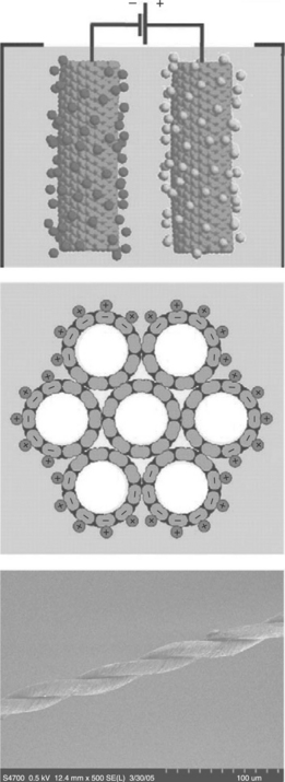
15.14 Charge injection in a CNT-based electromechanical actuator. Top: An applied potential injects charges into the two nanotube electrodes in solution (left: positive ions, right: negative ions). Middle: Charge injection at the surface of a nanotube bundle. Bottom: A scanning electron micrograph of a twist-spun MWNT yarn, which has a 0.6% actuator stroke at loads of 100 MPa.94
Electrostatic repulsive forces between like charges on the CNT work against the stiff carbon-carbon bonds in the nanotubes to elongate and expand the nanotubes, though quantum mechanical effects can predominate over electrostatic forces at low levels of charge injection. Unlike dielectric elastomers, strains are low (< 2%) since CNTs are extremely stiff. Actuation is generally achieved in films or yarns (Fig. 15.14 bottom) composed of many nanotubes. The porous nature of the films and fibres enables fast ion transport with response times of < 10 ms, with effective strain rates of 19%/s and effective power-to-mass ratios of 210 W/kg (half that of a high revving electric motor). The achievable response rate decreases with increasing nanotube yarn or sheet thickness, increasing interelectrode separation, and decreasing electrolyte ionic conductivity. A high work density combined with good temperature stability (> 450 °C in air, > 1000 °C in an inert environment) make CNTs prime candidates for situations where weight and temperature are important, such as aerospace and defence applications. Strains are relatively small compared with other polymer actuators (but an order of magnitude larger than found in typical piezoceramics). Strain could be increased by employing electrolytes such as highly purified ionic liquids that can withstand very large potentials without reacting electrochemically. CNT actuators have recently been shown to actuate when used as electrodes in a fuel cell. This possibility is exciting because the energy density of fuel cells is much higher than that of batteries, helping to enable autonomous applications of CNTs and possibly artificial muscle technology.
Research into field effect transistors (FETs) aims to replace the source/drain channel structure with a nanotube. Transistors assembled with carbon nanotubes may or may not work, however, depending on whether the chosen nanotube is semiconducting or metallic, over which the operator has no control. It might be possible to peel back layers from a MWNT to achieve the desired properties, but advances in microlithography are still needed to perfect this reduction method. Recent developments have focused media attention on nanotube nanoelectronic applications. Crossed SWNTs have been used to produce three- and four-terminal electronic devices along with non-volatile memory that functions like an electromechanical relay.
Irradiated by a camera flash, a random network of polyaniline (PANI) nanofibres was turned into a smooth and shiny film due to the highly efficient photothermal conversion and low thermal conductivity of PANI, which demonstrated a versatile new technique for making polymers into potentially useful structures.95 One of the great advantages of the flash-welding technique is that an area can be selectively welded by using a photomask, differing from other welding techniques like microwave welding. It is used to fabricate polymer films to pre-designed patterns. In addition, the technique can rapidly create asymmetric films, which are widely used in many applications such as separation membranes, chemical sensors and actuators.
Flat panel displays are one of the more lucrative applications of carbon nanotubes but are also one of the most technically complex. Nanotubes have an advantage over liquid crystal displays since they have low power consumption, high brightness, a wide viewing angle, a fast response rate and a wide operating range. In a flat panel display, electric fields direct field-emitted electrons toward an anode where phosphorus produces light. One demonstration used nanotube/ epoxy stripes on the cathode glass plate and phosphor-coated indium-tin-oxide (ITO) stripes on the anode plate. The pixels were at the intersections of the cathode and anode stripes. Pulses of ± 150 V were switched between the anode and cathode stripes to produce an image. Various types of carbon nanotube are being considered for future field-emission displays (FEDs). Samsung is a leading player in CNT-based FE displays.96 They have produced several prototype CNT-FEDs, including a 9-in. red-blue-green (RGB) colour FED that can operate at video frame speed. One beauty of the Samsung display is that the CNT-based cathode materials are printable inks.
In addition to flat panel displays, another potentially important application of CNT is in polymer-based light-emitting devices. The advantages of organic light- emitting diodes (OLEDs) based on conjugated polymers are low cost, low operating voltage, excellent processability and flexibility.97 However, their low quantum efficiency and stability have limited their application and development. Carbon nanotubes are also being considered as electron emitters for high- brightness lighting elements (Fig. 15.15).
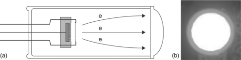
15.15 (a) Internal arrangement of a CNT-based lighting element. (b) Photograph of a CNT-based lighting element.98
Nanotube-based lamps are similar to displays, comprising a nanotube-coated surface opposing a phosphor-coated substrate, but they are less technically challenging and require less investment. With lifetimes expected in excess of 8000 h, they could replace environmentally problematic mercury-based fluorescent lamps used in stadium-style displays. More recently, lighting elements for the three primary colours have been produced and a brightness > 10 000 cd/m2 has been demonstrated.98 The frequency characteristics of the cold cathode element were studied over a range of frequencies. The cut-off frequency in these devices was found to be determined by the vacuum gap capacitance between the cathode and the gate electrode. The devices were repeatedly operated at 50 kHz without any degradation. It is quite feasible to use cold cathode lighting elements to assemble a full-colour display with video frame speed for large pixel screens. Nanotube-based gas discharge tubes might also find commercial use in protecting telecommunications networks from power surges. Another application arises if a metal target replaces the phosphorescent screen at the anode. This causes the accelerating voltage to increase, producing X-rays instead of light. The compact geometry of this nanotube-based X-ray generator could lead to use as an X-ray endoscope and for medical exploration.
Non-linear optical organic materials, such as porphyrins, dyes and phthalocyanines, have optical limiting properties, which can be used to control light frequency and intensity in a predictable manner in photonic devices. However, these are narrow-band optical materials. The combination of the unique properties of CNTs with conducting organic polymers (e.g., polyaniline, polypyrrole, polythiophene, poly(3,4-ethylenedioxy thiophene), poly(p-phenylene vinylene) and poly(m-phenylene vinylene-co-2,5-dioctoxy-p-phenylene)) makes these materials interesting multifunctional systems with great potential in many applications such as super-capacitors, sensors, advanced transistors, high-resolution printable conductors, electromagnetic absorbers, photovoltaic cells, photodiodes and optical limiting devices. As a result of the optical limiting performance and the good photoconductivity, special attention has been given to CNTs functionalized with polymers such as poly (N-vinyl carbazole).
15.4.4 Age and durability performance
The study of the degradation and stabilization of polymers is an extremely important area from a scientific and industrial point of view and a better understanding of polymer degradation will help to increase the life of a product.99 Polymer degradation in broader terms includes biodegradation, pyrolysis, oxidation, mechanical, photo- and catalytic degradation. Because of their chemical structure, polymers are vulnerable to harmful effects in the environment. In the following sections, epoxy and polyamides are considered. It is important to note that little attention has been given to the durability of polymer nanocomposites compared with their preparation techniques and the evaluation of mechanical properties.
Epoxy nanocomposites
The effects of hydrothermal aging on the thermomechanical properties of highperformance epoxy and its nanocomposites have been reported in the literature.100 It has been found that the storage modulus and relaxation behaviour are strongly affected by water uptake, while fracture toughness and Young’s modulus were less influenced. The dependence of tensile strength and strain at break on water uptake were found to be different in neat epoxy and epoxy-clay systems. Further improvements in flame retardancy (FR) using combinations of nanofiller and traditional FR-additives (e.g. aluminium trihydrate) have been observed. Nanocomposites based on nanofillers and aluminium trihydrate passed the UL 1666 riser test for fire-resistant electrical cables.101
There are two factors which have opposite influences on the thermal stability of epoxy–clay nanocomposites. The first is that the addition of clay to epoxy decreases the curing reactivity of epoxy resin. A lower reactivity of the resin generally results in a lower cross-linking density of the cured resin and longer polymer chains among the cross-linking points. A longer polymer chain is less stable thermally than a shorter chain, so nanocomposites with both long and short chains are easier to degrade than pristine epoxy resin. Secondly, silicate layers are good barriers to gases such as oxygen and nitrogen; they can insulate the underlying materials and slow the mass loss rate of decomposition products. Moreover, exfoliated nanocomposites have better barrier properties and thermal stability than intercalated ones. For intercalated nanocomposites (10 wt% clay), the first factor is dominant, whereas for exfoliated nanocomposites (2 wt% clay), the second factor is dominant. Becker et al.102 found that the water uptake (in an aquatic environment) was considerably reduced in epoxy nanocomposites with a particular clay loading percentage.
Jiang et al.103 investigated the resistance to vacuum ultraviolet irradiation of nano-TiO2 modified carbon/epoxy composites. The nano-TiO2 modified composites, including TiO2 + EP648 and M40/TiO2 + EP648, were fabricated so that the nano- TiO2 particles were dispersed in an EP648 epoxy matrix using a high-speed shearing emulsification technique. A jet type of vacuum ultraviolet (VUV) source was used to simulate the VUV spectrum in space, providing various doses of VUV irradiation. Experimental results showed that, compared with the EP648 epoxy and M40/EP648 composite, the specific area mass loss of TiO2 + EP648 decreased by 44% and that of the M40/TiO2 + EP648 composite by 38%. By increasing the dose of VUV irradiation, the internal layer shear strength of the M40/TiO2 + EP648 increased gradually, while that of M40/EP648 showed a decreasing trend. After irradiation, the surface of M40/TiO2 + EP648 changed a little, but that of M40/ EP648 was damaged severely. Scanning electron microscopy and atomic force microscopy observations showed that the VUV damage occurred mainly in the epoxy matrix, while the carbon fibres showed good resistance to irradiation.
In another study, Nguyen et al.104 investigated the degradation and potential nanofiller release of amine-cured epoxy nanocomposites containing multi-walled carbon nanotubes (MWCNTs) and nanosilica fillers exposed to UV radiation from 295 nm to 400 nm at 50 °C and 75% RH. During the exposure period, measurements of chemical degradation, mass loss and surface morphological changes were carried out on the samples. In a Fourier transform infrared spectroscopy (FTIR) analysis, the bands at 1508 cm− 1 and 1714 cm− 1, representing chain scission and oxidation, respectively, were used to follow various degradation processes of unfilled films and nano-filled epoxy composites exposed to UV radiation (Fig. 15.16). It can be seen that both unfilled and nano-filled amine-cured epoxy films underwent rapid chemical degradation when exposed to the UV, RH and temperature conditions. The degradation rates of all three materials (at or near the composite surface) reached a plateau in less than 10 days of exposure.
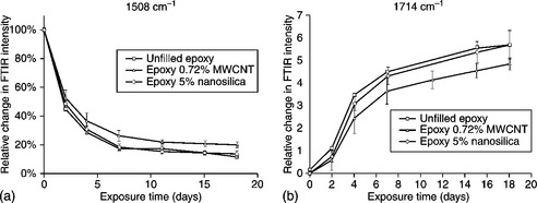
15.16 (a) Chain scission and (b) oxidation vs. time for unfilled, 0.72% MWCNT filled, and 5% nanosilica-filled amine-cured epoxy samples exposed to UV at 50 °C and 75% RH. Each data point is the average of four specimens and error bars represent one standard deviation.104
Lee and Lichtenhan105 reported that the molecular-level reinforcement of cages of polyhedral oligomeric silsesquioxanes (POSS) could significantly retard the physical aging process of epoxy resin in the glassy state. Barral et al.106 used kinetic parameters to predict the lifetime at different temperatures based on thermal degradation. The calculations showed that a POSS/diglycidyl ether of bisphenol A/4,4′-diaminediphenylmethane system can be used at room temperature for a very long time without failure. It must be emphasized that these calculations predicted the expected lifetime of epoxy-resin systems based only on thermal degradation data. Other factors, such as photodegradation, diffusion effects, mechanical and chemical degradation and physical aging, will also affect the expected lifetime. Finally, Ozcelik et al.107 recently studied the thermo-oxidative degradation of graphite/epoxy composite laminates due to exposure to elevated temperatures using weight loss and short beam strength reduction data. Test specimens obtained from 24-ply, unidirectional AS4/3501-6 graphite/epoxy laminates were subjected to 100, 150, 175 and 200 °C for 5000 h (208 days) in air. Predictive differential models for the weight loss and short beam strength reduction were developed using isothermal degradation data only up to 2000 h. The predictive capabilities of both models were demonstrated using the longer term, 5000 h, degradation data. The proposed models were first-order differential expressions, which can be used to predict degradation in an arbitrary, time- dependent temperature environment.
An investigation was undertaken by Barkoula into the environmental degradation of epoxy resin modified with MWCNTs and a carbon-fibre/epoxy composite reinforced with MWCNTs. The samples were exposed to hydrothermal loadings to assess the level of water uptake during loading at various temperatures. Both epoxy/CNT resin and the carbon-fibre/epoxy/CNT composites were tested in this manner. It was found that the modified epoxy resin showed a small increase in weight due to water uptake compared with the neat resin. The increase was thought to be caused by the additional interface between the CNTs and the epoxy, which created a route for water uptake. However, no correlation was found between the extent of CNT modification and the gain in weight. 108 When the composite laminates were tested, they showed a dramatic decrease in water uptake compared with the resin without carbon fibres. This was thought to be due to the introduction of carbon fibres, which do not absorb water. Figure 15.17 shows that there was very little difference between the neat and modified composites in terms of water uptake. The introduction of an interface at the microscale nullified the effect of the nanoscale interface between the CNTs and the epoxy matrix.
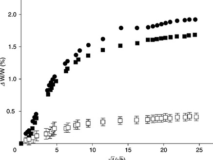
15.17 Weight gain due to water uptake against time for neat (![]() ) and 0.5% modified (
) and 0.5% modified (![]() ) epoxy, and neat (
) epoxy, and neat (![]() ) and modified (
) and modified (![]() ) carbon-fibre/ epoxy composites.108
) carbon-fibre/ epoxy composites.108
Polyamide nanocomposites
The presence of MWNTs improves the thermal stability of PA-6 under air obviously, but has little effect on the thermal degradation of PA-6 under a nitrogen atmosphere. A thermal degradation mechanism for PA-6 has been proposed by Levchik et al.109 VanderHart et al.110 observed that, in the presence of clay, the α-phase of PA-6 transforms into the γ-phase. Compared with pure PA-6, the PA-6/clay nanocomposite has a higher activation energy, lower thermal decomposition rate constants and better thermal decomposition stability.111 The activation energy (Ea) of PA-6/clay nanocomposites containing 1.2% and 3.5% clay is 174.47 and 309.175 kJ/mol, respectively, and that of pure PA-6 is only 143 kJ/mol. The effect of the modifier on the degradation of the nanocomposite was studied using 13C NMR. In the presence of a modifier (dihydrogenated-tallow ammoniumions) the nylon nanocomposite begins to degrade at 240 °C, whereas the virgin polymer does not. They concluded that the organic modifier is less stable. The combination of shear stress and temperature may lead to extensive degradation of the modifier and the extent of clay dispersion may not depend on the modifier.
Davis et al.111 studied the thermal stability of injection-moulded PA-6 nanocomposites using 13C NMR. Virgin PA-6 and its nanocomposites were injection moulded at 300 °C. PA-6 does not degrade at the processing temperature, whereas there was a significant decrease in the molecular weight of the nanocomposites under the same conditions. It was observed that the degradation might depend upon the percentage of water in the nanocomposites, which might cause hydrolytic cleavage. Fornes et al.112 found the formation of colour with polymer-matrix degradation after twin-screw extrusion of polymer nanocomposites. The researchers reported that the degradation of the nanocomposites depends on the type of nylon-6 materials as well as the chemical structure of the surfactant in the organically modified MMT. Hydroxyethyl groups in the surfactant, as opposed to methyl groups, and tallow substituents, as opposed to hydrogenated-tallow substituents, produce more colours in the nanocomposite, which was related to unsaturation in the alkyl ammonium surfactant causing considerable polymer degradation. The kinetic parameters of PA-6/clay nanocomposite decomposition have also been studied.
Pramoda et al.113 observed that the temperature required for the onset of degradation for PA-6 and 2.5% clay-filled nanocomposites was higher than other compositions (neat polymer, 5% and 7.5%, respectively). Gilman et al.114 proposed that, with the higher loading of clay, the temperatures required for the onset of degradation remain unchanged, which was attributed to agglomeration in the nanocomposites. The presence of organoclay (for PA-6/2.5 wt% clay nanocomposite) increased the activation energy for degradation, Ea, compared with neat PA-6 under N2. The major evolved gas products were cyclic monomers, hydrocarbons, CO2, CO, NH3 and H2O for PA-6 and PA-6/clay nanocomposites. During flammability measurements with a calorimeter in conjunction with an FTIR spectrometer in real time, changes in the condensed phase of PA-6 and a PA-6/clay nanocomposite revealed that the spectra obtained during burning are of sufficiently high quality to show the progression of the material in contact with the probe from a molten polymer to thermal degradation products. The spectral features are consistent with the evolution of caprolactam as a result of depolymerization.
In an intumescent ethylene vinyl acetate (EVA)-based formulation, using a PA-6/clay nanocomposite instead of pure PA-6 (carbonization agent) has been shown to improve the fire properties of the intumescent blend. Using clay as a ‘classical’ filler gave the same level of FR performance in the first step of combustion as when directly using exfoliated clay in PA-6. But, in the second half of combustion, the clay destabilizes the system and increases flammability. Moreover, kinetic modelling of the degradation of the EVA-based formulations shows that adding clay to the blend gives the same mode of degradation and the same invariant parameters as for the PA-6/clay nanocomposite containing the intumescent blend. The increase in flammability of the standard flammability test paper, K-10, in the second half of combustion shows the advantages of using nanoclay rather than microclay in an intumescent system.110
The efficiency of the self-protective coatings, which form during pyrolysis and thermo-oxidative degradation (in the presence of oxygen), of a PA-6/clay nanocomposite has also been investigated. 114 The nanocomposite itself can be protected from fire, flames and oxygen by coating the organosilicon thin films. PA-6 and PA-6/clay nanocomposite (PA-6 nano) substrates were coated by polymerizing A 1,1,3,3-tetramethyldisiloxane (TMDS) monomer doped with oxygen using the cold remote nitrogen plasma (CRNP) process. The thermal degradation of deposits under pyrolytic and thermo-oxidative conditions shows that the residual weight evolution with temperature depends on the chosen atmosphere.
Organically modified clay-reinforced PA-6 was subjected to accelerated heat aging to estimate its long-term thermo-oxidative stability and useful lifetime compared with the virgin material.115 Changes in molecular weight and thermal and mechanical properties were monitored and considered to be due to the polymer modification encountered during aging. Generally, the strong interaction between the matrix and the clay filler renders the polymer chains, especially those adjacent to silicates, highly restrained mechanically, so that a significant portion of an applied force is transferred to the higher modulus silicates. This mechanism explains the enhancement of tensile modulus that the non-aged clay-reinforced PA-6 exhibited (1320 MPa) compared with the neat polymer (1190 MPa), as shown in Fig. 15.18.
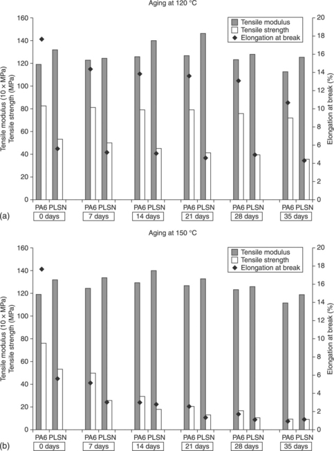
15.18 Tensile properties of PA-6 and a PA-6 layered silicate nanocomposite (PLSN), oven-aged at (a) 120 °C and (b) 150 °C.115
Enhancing and monitoring structural stability and durability
In conventional fibre-reinforced polymers (FRPs), fibre-orientation is usually in-plane (x- and y-directions), resulting in fibre-dominated material properties in these directions, whereas the matrix dominates in the z-direction. Therefore, FRPs are very sensitive to intrinsic damage such as delamination (in particular), matrix cracking and fatigue damage. Moreover, their use as structural materials in aerospace applications has increased from less than 5% by structural weight to 50% (mainly due to the need to reduce weight and save fuel), which has raised many questions relating to vibration and acoustic damping, tribological behaviour and hygroscopic properties. Therefore, for enhanced structural stability, durability and performance, it is necessary to address and accommodate these undesirable issues.
Several approaches have been independently adopted to tackle these problems, which include: (a) using epoxy/elastomer blends at ply interfaces, (b) incorporating interleaved viscoelastic layers, (c) reducing the mismatch in elastic properties (and stress concentrations) at the interfaces between laminated plies and (d) using carbon filaments in place of interleaves. These approaches have their own positives and negatives as these materials are ‘functional’ rather than ‘structural’ and their high cost, low strain/stiffness, compatibility/adhesion with FRP laminates, or poor processability always results in a compromise.
A specific area of interest is in tuning an interleaved material to achieve the desired multifunctionalities or to enhance the desired properties compared with FRPs without interleaf layers.
In non-destructive evaluation, damage sensitivity and the reinforcing effects of carbon nanocomposites could be obtained from electrical volume and contact resistivity measurements using acoustic emission techniques. Adding conductive particles to an isolating polymer can result in an electrically conductive composite, if the particle concentration exceeds the percolation threshold, which is the particle volume fraction required to form a conductive network through the bulk polymer. Because of their high aspect ratios, CNTs are very effective fillers in the promotion of electrical conductivity in polymeric matrices. Percolation thresholds as low as 0.0025 wt% have been reported using MWNTs in an epoxy matrix. 116 The percolation threshold for the materials and the dispersion process used in another work was found to be below 0.1 wt%.11 Conductivities of up to 2 × 10− 2 S/m were achieved with unfunctionalized CNTs. The functionalization of CNTs with amino groups usually increases the percolation threshold and decreases the maximum achievable conductivity, because the graphitic structure of the nanotubes incurs some defects during the functionalization process.
Furthermore, the average length of a nanotube is reduced, which explains the increasing percolation threshold.11, 117 Park et al.118 explored this concept by applying the electro-micromechanical technique to obtain fibre damage and the reinforcing effect of carbon nanocomposites against content. The sensitivity to fibre damage such as fibre fracture, matrix deformation and fibre tension was highest for 2.0 vol% CNT composites. They suggested that damage sensitivity as measured by electrical resistance might be closely related to the 3D network structure, the percolation structure. For CNT composites, the mechanical properties and apparent modulus indicate that the reinforcing effect increased with CNT content. The researchers confirmed that the apparent modulus, as measured by electro-micromechanical tests, could be used to evaluate the mechanical properties of fibre-reinforced composites. The reinforcing effect on the mechanical properties and apparent modulus was highest for 2.0 vol% CNT, compared with percolation structures with 0.1 and 0.5 vol% CNT. Morphological trends were consistent with damage sensitivity based on electrical properties.
The optimal use of sensor technology is in itself crucial in the design, manufacture, maintenance and correct functioning of a number of aerospace- and defence-related adaptive structures and other strategic equipment. Electrode materials with carbon nanotubes perform better than traditional carbon electrodes, with good conducting ability and high chemical stability. Another possible application could use the inherent multifunctionality of CNT-based materials for designs that are self-sensing – sensor skins capable of probing the environment around a vehicle could be designed so that they are part of the vehicle itself. Their multifunctionality arises because nanotubes can be either metallic or semiconducting based on their chirality. Hence, SWNTs have been used to fabricate several nanoscale devices, such as field-effect transistors and molecular logic devices. Furthermore, simply changing the environment around a nanotube can change its conducting behaviour. This phenomenon has been exploited to create sensors capable of measuring several parameters for a vehicle’s structural health (i.e. strain, pressure, temperature, etc.). For aerospace systems, innovative lighter and smaller sensors can be used for enhanced real-time prognostic health monitoring and the diagnosis of aerospace and military structures, such as in strategic or tactical transportation and weapon systems. However, as mentioned above, there are concerns that the current maintenance techniques cannot meet the growing demand for high reliability and readiness. New, advanced, built-in diagnostic techniques have to be developed, which can perform damage diagnosis automatically and without human error; provide advanced warning of structural failure to pilots or operators; minimize unnecessary downtime for scheduled maintenance; maintain reliability and improve the safety of aging structures; reduce maintenance costs and enhance combat readiness.
15.4.5 Impact resistance and energy absorption
Damage due to low- and high-velocity impact events weakens the structure of composite materials due to a continuous service load. Furthermore, an impact may generate different types of flaws before full perforation, i.e. sub-surface delamination, matrix cracks, fibre debonding or fracture, indentation and barely visible impact damage (BVID). Over time, these effects can induce variations in the mechanical properties of composite structures (the primary effect of a delamination is to change the local value of the bending stiffness and the transverse-shear stiffness), leading to possible catastrophic failure. It has been reported that the energy-absorption capability and related properties of polymer matrices can be engineered by adding nanoscale fillers. For example, rigid nano-sized particles such as SiO2, TiO2, CaSiO3, Al2O3 powder, CNTs and clay nanoplatelets have been used, and some important findings are summarized in this section.
Typical fillers for the reinforcement of polymer matrices are particles (e.g. silica or aluminium oxide particles), tubes (e.g. nanofibres or nanotubes) and plates (e.g. nanoclay platelets). Significant enhancement of the impact strength of polymeric nanocomposites has been achieved by adding amino-functionalized MWCNTs or small amounts of single-walled carbon nanotube (SWCNTs). The sensitivity of FRPs to intrinsic damage (delamination, matrix cracking and fatigue) and their minimal multifunctionality requires a significant effort to improve their performance to meet spacecraft application standards. Currently, however, there are many questions surrounding the incorporation of nanoparticles, like CNTs and CNFs, in FRPs with regard to manufacturing methodology and structural integrity. The toughening of particle-modified semi-crystalline polymers is related to the inter-particle distance, s, for any type of added particle. The distance s depends on both the concentration, u, and the average size, d, of the particles.
A number of experiments have shown that fracture toughness improved with the addition of clay nanoplatelets to epoxy when the clay nanoplatelets were not fully exfoliated and intercalated clay nanoplatelets were present. Such very high improvements are not typically observed for composites reinforced with conventional micro-particles. Subramaniyan and Sun44 reported that core/shell rubber (CSR) nanoparticles, having a soft rubber core and a glassy shell, improved the fracture toughness of an epoxy vinyl ester resin significantly more than MMT nanoclay particles with the same weight fraction. However, hybrid blends of CSR and nanoclay were found to give the best balance of toughness, modulus and strength. The same investigators highlighted that, when the nanoclay particles were used to enhance the polymer matrix in a conventional glass-fibre-reinforced composite, the interlaminar fracture toughness of the composite was less than that of the unreinforced composite. It was suggested that a possible reason for this result was the arrangement of the nanoclay particles along the fibre axis.
Two factors affect the capacity of rigid particles for energy dissipation at high loading rates:
• the ability of the dispersed particles to detach from the matrix and to initiate the local matrix shear in the vicinity of voids and
Therefore, the optimal minimal rigid-particle size for polymer toughening should fulfil two main requirements: to be smaller than the critical size for polymer fracture and also to have a debonding stress that is small compared with the polymer matrix yield stress.
Most of the studies that noted an increase in toughness by incorporating CNTs in polymers (both thermosets and thermoplastics) have attributed it mainly to the nanotube pull-out mechanism and the bridging of cracks in the matrix. The nanotube pull-out mechanism was inspired by conventional polymer/fibre composites where fibre/matrix debonding and fibre pull-out (including work done against sliding friction in pulling out the fibre) govern the extent of energy absorption. Hence, the very high interfacial areas in polymer/nanotube composites are expected to result in drastic improvements in the work necessary for fracture due to nanotube pull-out. To explain and confirm the pull-out mechanism, Barber and co-workers119 studied the pull-out of individual nanotubes by attaching them to the end of a scanning probe microscope (SPM) tip and pushing them into a liquid epoxy polymer (or liquid melt of polyethylene-butene). After the polymer had solidified, the nanotube was pulled out and the forces were recorded from the deflection of the SPM tip cantilever. Although this provided an estimate of the interfacial strength of individual nanotubes, it is not directly relevant to pull-out toughness measurement, which depends on many factors like the alignment/ orientation and flexible/entanglement nature of the nanotubes. Even by increasing the embedded length of the nanotube in the resin, the nanotube breaks instead of being pulled out from the polymer.
Nanotube-reinforced structures have up to eight times higher tensile strength and advanced energy dissipation mechanisms, so more damping can be achieved with smaller and lighter structural designs. The number of CNT walls and their size affects stress concentration in the composite, and thus short and even round particles are strongest (like diamonds, etc.). However, longer fibres are flexible and may be better for damping. A CNT may act as a nanoscale spring and a crack-trapping material in composites. These damping phenomena could be multiplied when CNTs are dispersed. Orientation and geometry (waviness) of CNT particles may affect the mechanisms of energy dissipation and fracture mechanics. Maximum stiffness is achievable when the longitudinal orientation of CNTs is 90°. Notably, open-end CNTs do not collapse, fail or buckle due to higher stress concentrations, while many researchers have used closed-end CNT-reinforced composites. Thus isolated SWNTs may be desirable for damping applications due to their significant load-bearing ability because of CNT/matrix interactions. Defects of the carbon particles likely limit performance. In future, CNTs may serve as storage containers for sealant or multi-purpose particles of another material.
A Kireitseu et al.120 study on the rotating fan blades of turbine engines represents another feasible aerospace or defence application. The authors considered a large rotating civil engine blade, illustrated in Fig. 15.19, which is typically hollow and usually has stiff rib-like metallic structures in order to increase rigidity and maintain the cross-sectional profile of the blade. They suggested a foam-filled fan where the metal structure or traditional fillers are replaced with a CNT-reinforced syntactic foam and, also, with a CNT-reinforced composite layer on the top. Results of the damping behaviour and impact toughness of the composite sandwiches showed that CNT-reinforced samples have better impact strength and vibration-damping properties over a wide temperature range. Experiments conducted using a vibrating clamped beam with the composite layers indicated up to a 200% increase in the inherent damping level and a 30% increase in the stiffness with some decrease (20–30%) in the density of the composite. The crosslinks between the nanotubes and composite layers also served to improve the load transfer within the network, resulting in improved stiffness properties. The critical issues to be considered include: the choice of nanotubes and related matrix materials for vibration damping; tailoring the nanotube/matrix interface with respect to the matrix; and the orientation, dispersion and bonding of the nanotubes in the matrix. It is anticipated that significant weight, thickness and manufacturing cost reductions could be achieved in this way.
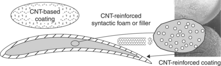
15.19 Damping material for an aircraft engine blade.120
The critical parts in aerospace vehicles depend on both the strength and toughness of the materials they are made of, while the associated technology places strict limitations on the weight of the different components. Notably, matrix toughening may be performed through chemical modification or, more recently, with the incorporation of fillers in the matrix material. An interface can be modified by grafting in order to tailor the chemical compatibility between the fibres and the matrix. In this way, despite their size, nanofillers can have a significant presence in a small zone. In contrast, only a few micro-particles participate in plastic zone deformation. It then follows that nanofillers can lead to better fracture properties of a brittle matrix, resulting in enhancement of the matrix fracture toughness, which can lead to an overall advanced fracture behaviour. Additionally, by involving more nanofibres during delamination the nanofibres can act as reinforcing fibres, thus increasing fracture toughness. These approaches may offer alternatives to the conventional interlaminar toughness improvement of fibre- reinforced composites (especially high-performance, high-temperature composites), which has been addressed in various ways, such as by tailoring the matrix or interface properties, stitching, Z-pinning or interleaving. These approaches also improve mechanical properties, such as fatigue life. Coiled CNTs (Fig. 15.20) are another option for advanced composite reinforcement technology.
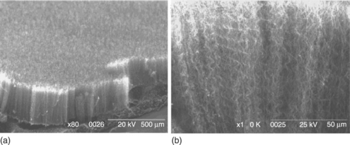
15.20 (a) Typical SEM image of an aligned coiled nanotube array. (b) Enlarged cross-section of densely packed aligned coiled nanotubes.121
Traditional straight carbon nanotubes are recognized as strong reinforcements, which substantially enhance the strength of composites. However, the drawbacks, such as the decrease of fracture toughness and subsequent increase of the brittleness of the composites, may restrict the utilization of these reinforcements for some composite structures. Coiled nanotubes are ideal reinforcements for composite and polymer-based materials. These reinforcements can provide moderate strength improvement as well as enhancing the fracture toughness of the composites without substantially increasing the weight and damaging the nanotube structures.
15.5 Future trends: opportunities and challenges
The use of polymer nanocomposites in structures has several predictable benefits for aerospace structures, primarily by providing safer, faster and eventually cheaper transportation in the future.122−124 The most obvious of these is significant airframe weight reduction stemming from the low density of polymer nanocomposites and complemented by their high strength and modulus. However, the application to real products is in its infancy and much remains to be achieved.
Experiments on a fully integrated nanotube composite using CNTs have demonstrated a dramatic enhancement of mechanical properties. To demonstrate potential airframe applications, O’Donnell et al.125 conducted a mass analysis study on CNT-reinforced polymer-structured aircraft. The analysis considered a notional Boeing 747–400 and 757–200, an Airbus A320 and an Embraer E145 with a CNT-reinforced polymer (CNRP) as the primary structural material. The entire volume of structural aluminium was replaced with CNT-reinforced polymer, without any modifications to the geometry or design of the airframe. Each airframe modelled saw an average 17.32% weight reduction in the low initial take-off mass category with a minimum mass reduction in the high initial take-off mass category of over 10%. The average fuel saving for all CNRP-structured airframes was 9.8%. Though the probability of CNT-reinforced polymer-structured substitution in existing airframes is unlikely, this type of analysis provides an insight into a small group of benefits when a nano-structured material is applied on the macroscale.
By combining them with conductive polymers, such as PANI, nanotubes can be used for sensitive electrochemical sensors. It has been observed that, with an increase in nanotube concentration, the conductivity of PANI/nanotube films and the current level in the metal/semiconductor devices increases, even at elevated temperatures. Research has also proved that the electrical conductivity increased with the number of nanotubes used in the epoxy-based materials. Volodin et al.126 used coiled nanotubes as a mechanical resonant sensor, which is a significant achievement among many promising applications.
CNTs have tremendous promise in improving the performance of power devices such as thin-film polymeric solar cells, direct-methanol fuel cells, lithiumion (Li+) batteries, ultra-capacitors and thermionic power supplies.127 Exceeding the state-of-the-art performance of these devices by using carbon nanotubes, in some cases by merely substituting conventional materials with them, is no longer seen as a proposition but is rapidly becoming reality.
Various advanced composite coatings have been used to improve durability, reliability and performance of many aircraft and armoured-vehicle components. Generally speaking, coatings are significant in many potential aerospace applications. Multifunctional nanocoatings currently in development for aerospace applications include environmentally safe materials for corrosion sensing and protection, and using them on aircraft skins for sensing mechanical damage. Protective coatings for high-performance, high-temperature applications require the development of nanoparticles and nanocomposites, which are a combination of nanoparticles and matrix materials, to form the anti-wear and anticorrosion coatings. Conventional paints are often not only health hazards, but are also labour intensive to develop and to apply. Carbon nanotubes could be used to replace carbon black in powder paints as cost-effective conductive fillers for electrostatic spray painting of vehicular body parts, leading to more durable, corrosion-resistant paints and surfaces. Other applications use the effect of different particles on strength, toughness, thermal transport and various stealth effects. Experimental results 128 have shown that replacing carbon black with CNTs improves skid resistance and reduces tyre abrasion. Other possible applications range from semiconductors, electronic memory, drive products and medical delivery systems to uses in plastics such as vehicle body panels, paint, tyres and as flame retardants in polyethylene and polypropylene.
Single-wall carbon nanotubes have recently been incorporated into poly (3-octylthiophene) (P3OT) to promote exciton dissociation and improve electron transport in a polymeric solar cell.128 Conducting polymers like P3OT have attracted significant attention in the photovoltaic community since they produce excitons (quantum mechanical particles consisting of bound electron–hole pairs) after optical absorption. When the polymer is placed in a properly structured device with a suitable dopant to promote dissociation of the exciton and conduction of the electron, hole conduction proceeds through the polymer and contributes to an overall photocurrent. SWNTs are an appropriate dopant in these polymers since electron affinity is higher for a SWNT compared with P3OT and electron transport in a metallic SWNT is typical of a ballistic conductor. In addition, the high aspect ratio of a SWNT leads to low doping levels necessary to achieve a sufficient percolation network for high electrical conductivity, while retaining the mechanical properties required for a flexible polymeric device. Clearly, polymer/ CNT nanocomposites are an alternative class of organic semiconducting materials, which promise improved performance for organic photovoltaic cells and devices. It is obviously beneficial to design photoconductive devices with a high efficiency in charge carrier generation.
Based on the fact that that the best way to achieve multifunctional properties in a polymer is to blend it with nanoscale fillers, several investigators have reported that the incorporation of nanoparticles in conventional FRPs enhances combinatorial properties at relatively low loadings of filler compared with their microscale and macroscale counterparts. It is thought that nanofillers (particularly high-aspect-ratio CNTs) increase matrix properties, especially in the z-direction, by infiltrating between the microscale fibres. Nevertheless, there are many discrepancies and uncertainties in the literature on the mechanical and functional properties and the manufacturing methodologies. It is also necessary to look at these factors from the viewpoints of both binary nanocomposites and ternary hybrids, to give an in-depth understanding and achieve the desired multifunctionality in these materials.121, 130, 131
Despite the excellent strength, modulus and electrical and thermal conductivities along with the low density of CNTs, their potential after incorporation into polymers has not been fully realized and the properties of the nanocomposites obtained are often below the predicted values. This is true even after discounting the difficulties associated with disaggregating and controlling their dispersion in polymers (due to their entangled, intertwined networks, high intermolecular van der Waals interactions, differences between single- and multi-walled nanotubes, which affects their surface areas and interfaces, etc.). Most studies to date have reported improvements in stiffness and strength, but toughness results are rather uncertain and require further property optimization studies.
The preparation of nanocomposites of polymers and nanofillers has interested researchers because of their flame retardancy and good mechanical and electrical properties. The dispersion of the fillers is currently difficult and mainly achievable by functionalizing CNTs. Reports on polymer/CNT nanocomposites have mainly focused on the functionalization of CNTs, their preparation and property developments. Unfortunately, or fortunately, the environmental durability of nanocomposites has yet to be studied.
Moreover, it is also important to consider the nanoscopic confinement effect of nanoparticles on the surrounding matrix and the matrix/nanoparticle interface as it has a direct effect on the properties of nanocomposites. Confinement is in turn determined by the size range and dimension of the fillers. For example, size differences between CNTs and CNFs affects their responses under stress conditions. In thermoplastic polymer nanocomposites, it has been noted that with high-aspect-ratio nanoscale fillers (like CNTs and clay) preferential orientation of the polymer lamellae occurs regardless of crystallographic lattice matching (between the polymer chain and the filler crystal).
While with CNFs lattice matching is a prerequisite, it has been revealed that the formation of epitaxially grown transcrystalline regions (due to crystallographic lattice matching) does not guarantee a strong interface between the fillers (where the size or dimensions are not nanoscale) and polymer chains. For example, a TEM micrograph of a polymer/CNF nanocomposite tensile stretched to an extension of 60% clearly revealed partial debonding of the CNFs along the interface. This, in fact, follows conventional rigid-particle toughening of polymers and is based on the interface between the nanoparticles and the polymer matrix. That is, particles must debond at the interface and create a free volume in the material on a submicron level to relieve the constraint adjacent to the crack tip. Similarly, in epoxy/rubber binary blends, cavitation of rubber particles occurs, which releases the high plastic constraint and activates large-scale plastic deformation of the surrounding matrix material. But, with CNTs and other ‘nanoscale’ fillers, this debonding may be hindered due to the strong tethering junctions with the matrix, ultimately resulting in a brittle failure.
Furthermore, in thermosets, the presence of nanoscale fillers is expected to influence the local cross-linking density (in the vicinity of the fillers) and melt viscosity, which in turn have a drastic effect on the bulk mechanical properties and also the glass transition and heat distortion temperatures of the composites. Hence, an in-depth understanding of the processing and structural properties of these materials is necessary to fully exploit the functional characteristics of CNTs and CNFs.
Researchers have incorporated nanoparticles in conventional structural materials generally using a two-step protocol.132 Gojny et al.10 used a conventional calendering technique to disperse carbon nanotubes in epoxy resins. This approach utilizes adjacent cylindrical rolls counter-rotating at different velocities to impart high shear stresses (Fig. 15.21).
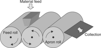
15.21 Calendering using three-roll milling.10
The mixture must pass through the narrow gap (~ 5 μm) between the rotating cylinders and so intense uniform shearing is achieved over the entire volume of the material. The suspension of epoxy/nanoparticles was collected and RTM was used to infiltrate the fibre fabric. An electrical field was applied in some cases during curing to enhance orientation of the nanofillers in the z-direction. It should be noted that conductivity in the in-plane direction was found to be of the order of 1 × 10⁻² S/m, while the conductivity in the z-direction was ~ 1 × 10 −6 S/m (and ~ 3 × 10 −5 S/m with an applied electric field during curing), which is still in the antistatic range. The reserachers reported that the interlaminar shear strengths of hybrid materials significantly improved with only 0.3 wt% of CNTs (multi-walled) compared with FRPs without nanoparticles.
A number of studies have revealed that the stiffness, compressive strength and even interfacial/interlaminar shear strength of ternary composites (with CNTs, CNFs or carbon black) were improved compared with binary laminates.133 Despite lacking any strong evidence, it is thought that the cracks due to fibre rupture or interfacial debonding and even interlaminar delamination could be bridged by CNTs or CNFs, thus improving the interfacial strength and toughness. Another important factor to consider is the type of resin and hardener. Differences in these have been observed to give dramatic variations in mechanical properties of some hybrid ternary nanocomposites at similar loadings of fillers. A significant number of studies have reported that improved compressive strength, lessening of microcracking and improved interlaminar fracture toughness have been achieved compared with binary conventional FRPs. Although this reinforces the benefits of incorporating nanoparticles in conventional FRPs, the majority of these investigations are preliminary and do not provide an in-depth understanding of the various factors, such as compatibility of the three phases, their interfaces, microstructural variations, nanoparticle network formation, percolation threshold variations or even the mechanisms of damage. But it is of the utmost importance to understand these factors in order to predict the long-term durability of these materials, which is necessary for their successful industrialization.
Overall there is an essential requirement to investigate the durability of these nanocomposites in different environmental conditions to extend the applicability of these hybrid materials. Further, the current limited knowledge of the degradation mechanism of polymer nanocomposites has led to the development of more efficient stabilizers for improving product performance on one hand and, on the other, the development of sensitizers to produce degradable polymers and to preserve the environment. The degradation of polymers has harmful as well as beneficial aspects. If unchecked it can play havoc with the performance of polymer nanocomposites, causing a fire safety hazard or toxicity, but if properly harnessed it can be used for producing new and better materials. It will be worthwhile to focus further studies on nanoparticulates such as clay, carbon nanotubes, metal oxides and metal salts, considering degradation in the environment where they are to be utilized, for example for specific aerospace and military applications. Despite the positive results of much previous research, it has been indicated that nanotubes could be more toxic than other carbon particles or quartz dust when absorbed into lung tissue.134 Fundamental to the success of nanotechnology will be its perceived safety by the public. Many concerns have been aired concerning the use of manufactured nanoparticles.
15.6 Conclusions
Fibre-reinforced composites are a type of engineered material, which exhibits high strength/weight and modulus/weight ratios compared with some metallic materials. In the last two decades, studies have shown the potential improvement in properties and performance of fibre-reinforced polymer matrix materials in which nanoscale and microscale particles have been incorporated. The technology of nanoscale and microscale particle reinforcement can be categorized as inorganic layered clay technology, single-walled and multi-walled carbon nanotube technology, carbon nanofibre technology and metal particle technology. To date, the nanoparticle reinforcement of fibre-reinforced composites has been shown to be a possibility, but much work remains in order to understand how nano-reinforcement results in major changes in material properties. An understanding of these phenomena will facilitate their extension to the reinforcement of more complicated anisotropic structures and advanced polymeric composite systems.
One of the technological drawbacks is that mechanical reinforcement through the application of nanoparticles as a structural element in polymers is more difficult to realize and still remains a challenging task. Efficient exploitation of nanoparticle properties in order to improve material performance is generally related to the degree of dispersion, impregnation in the matrix and interfacial adhesion. The advantage of nanoscale compared with microscale fillers is their enormous surface area, which can act as an interface for stress transfer. The methods published so far on the improvement of the mechanical properties of polymer composites have mainly focused on optimizing the manufacturing processes for the composites, i.e. by using prepared nanoparticles. The property and performance enhancements made possible by nanoparticle reinforcement may be of great use for carbon- or glass-fibre/epoxy composites used in highperformance and high-temperature applications such as aerospace engine components and nacelles, the storage of cryogenic liquids and motorsports. However, precautionary measures should be observed at high temperatures since the structure and properties of these materials can change radically when they are exposed to extreme temperatures, especially in a cyclical fashion.
Better dispersion of the nano-sized, silicate-based filler in matrix systems is expected to yield improved material properties in several areas. Various mechanical properties, specifically improved fracture toughness as well as improved flame-retardant effects, are of interest. A key objective of ongoing worldwide research is investigating whether a nano-modified matrix yields improved delamination resistance in a fibre-reinforced laminate compared with a laminate with a neat polymer as the matrix material. It is necessary, however, to evaluate the damage resistance characteristics of three-phase nanocomposite laminates with regard to their applicability as structural elements. Further, as mentioned above, another complication is that the microstructure of semi-crystalline polymer matrices is influenced not only by the processing history but also by the presence of nanoparticles. The addition of various types of carbon nanotubes, nanofibres or nanoclays to polymers has already been observed to influence the crystallization kinetics and resulting morphology. Such changes in matrix morphology need to be considered when evaluating nanocomposite performance with regard to the intrinsic filler properties. The effects of nanoparticles on such oriented polymer systems, although significant, have not yet been fully established. In addition, as mentioned above, the presence of additives such as colouring pigments has been shown to influence matrix morphology during fibre spinning, and there is the whole technology of nucleating agents, which are deliberately added to influence crystalline microstructure.
Further, through nanoparticle reinforcement, an electrically conductive matrix could provide enhanced possibilities including stress–strain monitoring or damage detection. The application of an electrical field is known to orient the nanoparticles in the in-field-direction, which may result in increased efficiency of the z-reinforcement of the laminates. As a further benefit, electrical conductivity in the z-direction should increase with this approach. Nanoparticles, especially CNTs, have a high potential in the modification of polymers. They are very effective fillers regarding mechanical properties, especially toughness. Moreover, they allow the introduction of functional properties, which are connected to their electrical conductivity, into polymeric matrices. The electro-micromechanical technique has been studied as an economical non-destructive evaluation method for damage sensing and the characterization of interfacial properties because conductive fibre can act as a sensor itself as well as acting as a reinforcing fibre.
15.7 Acknowledgements
Financial support from the Research Councils United Kingdom (RCUK) through Grant No. EP/C509277/1 is acknowledged.
15.8 References
1. Gong, X., Liu, J., Baskaran, S., Voise, R.D., Young, J.S. Surfactant- assisted processing of carbon nanotube/polymer composites. Chemistry ofMaterials. 2000; vol. 12(4):1049–1052.
2. Shaffer, M.S.P., Windle, A.H. Fabrication and characterization of carbon nanotube/poly(vinyl alcohol) composites. Advanced Materials. 1999; vol. 11(11):937–941.
3. Park, C., Ounaies, Z., Watson, K.A., Crooks, R.E., Smith, J., et al. Dispersion of single wall carbon nanotubes by in situ polymerization under sonication. Chemical Physics Letters. 2002; vol. 364(3–4):303–308.
4. Martin, C.A., Sandler, J.K.W., Windle, A.H., Schwarz, M.-K., Bauhofer, W., et al. Electric field-induced aligned multi-wall carbon nanotube networks in epoxy composites. Polymer. 2005; vol. 46(3):877–886.
5. Shi, D., He, P., Lian, J., Chaud, X., Bud’ko, S.L., et al. Magnetic alignment of carbon nanofibers in polymer composites and anisotropy of mechanical properties. Journal of Applied Physics. 2005; vol. 97:64312. [-1].
6. Shi, D., He, P., Lian, J., Chaud, X., Beaugnon, E., et al. Plasma coating and magnetic alignment of carbon nano fibers in polymer composites. JOM. 2004; vol. 56:129–130.
7. Olek, M., Kempa, K., Jurga, S., Giersig, M. Nanomechanical properties of silica-coated multiwall carbon nanotubes-poly(methyl methacrylate) composites. Langmuir. 2005; vol. 21(7):3146–3152.
8. Star, A., Stoddart, J.F., Steuerman, D., Diehl, M., Boukai, A., et al. Preparation and properties of polymer-wrapped single-walled carbon nanotubes. Angewandte Chemie - International Edition. 2001; vol. 40(9):1721–1725.
9. Bhattacharyya, S., Sinturel, C., Salvetat, J.P., Saboungi, M.L. Protein- functionalized carbon nanotube-polymer composites. Appl. Phys. Lett.. 2005; vol. 86(113):104.
10. Gojny, F.H., Wichmann, M.H.G., Köpke, U., Fiedler, B., Schulte, K. Carbon nano tube-reinforced epoxy-composites: enhanced stiffness and fracture toughness at low nanotube content. Composites Science and Technology. 2004; vol. 64(15):2363–2371.
11. Gojny, F.H., Wichmann, M.H.G., Fiedler, B., Bauhofer, W., Schulte, K. Influence of nano-modification on the mechanical and electrical properties of conventional fibre-reinforced composites’, Composites. Part A: Applied Science and Manufacturing. 2005; vol. 36(11):1525–1535.
12. Wichmann, M.H.G., Sumfleth, J., Gojny, F.H., Quaresimin, M., Fiedler, B., Schulte, K. Glass-fibre-reinforced composites with enhanced mechanical and electrical properties - Benefits and limitations of a nanoparticle modified matrix. Engineering Fracture Mechanics. 2006; vol. 73(16):2346–2359.
13. Zhao, D.L., Qiao, R.-H., Wang, C.-Z., Shen, Z.M., Microstructure and mechanical property of carbon nanotube and continuous carbon fiber reinforced epoxy resin matrix composites. Proceedings of the Asian International Conference on Advanced Materials (AICAM2005). Trans Tech Publications, Beijing, China, 2006:517. [3–5 November 2005].
14. Hsiao, K., Alms, J., Advani, S.G. Use of epoxy/multiwalled carbon nanotubes as adhesives to join graphite fibre reinforced polymer composites. Nanotechnology. 2003; vol. 14(7):791–793.
15. Meguid, S.A., Sun, Y. On the tensile and shear strength of nano- reinforced composite interfaces. Materials & Design. 2004/6; vol. 25(4):289–296.
16. Hussain, M., Nakahira, A., Niihara, K. Mechanicalproperty improvement of carbon fiber reinforced epoxy composites by Al2O3 filler dispersion. Materials Letters. 1996; vol. 26(3):185–191.
17. Mahfuz, H., Adnan, A., Rangari, V.K., Jeelani, S., Jang, B.Z. Carbon nanoparticles/whiskers reinforced composites and their tensile response. Composites. Part A: Applied Science and Manufacturing. 2004; vol. 35(5):519–527.
18. Iwahori, Y., Ishikawa, T. Mechanical properties of CFRP using dispersed CNF resin. Proceedings of the Third Japan-Korea Joint Symposium on Composite Materials. vol. 191(192), 2002.
19. Iwahori, Y., Ishiwata, S., Sumizawa, T., Ishikawa, T. Mechanical properties improvements in two-phase and three-phase composites using carbon nano-fiber dispersed resin. Composites. Part A: Applied Science and Manufacturing. 2005; vol. 36(10):1430–1439.
20. Yokozeki, T., Iwahori, Y., Ishiwata, S. Matrix cracking behaviors in carbon fiber/epoxy laminates filled with cup-stacked carbon nanotubes (CSCNTs). Composites. Part A: Applied Science and Manufacturing. 2007; vol. 38(3):917–924.
21. Spindler-Ranta, S., Bakis, C.E., Carbon nanotube reinforcement of a filament winding resin. SAMPE 2002. 2002:13. [12–16 May, Long Beach, CA].
22. Veedu, V.P., Cao, A., Li, X., Ma, K., Soldano, C., et al. Multifunctional composites using reinforced laminae with carbon-nanotube forests. Nature Materials. 2006; vol. 5(6):457–462.
23. Usuki, A., Kawasumi, M., Kojima, Y., Okada, A. Swelling behavior of montmorillonite cation exchanged for ω-amino acids by ϵ-caprolactam. Journal of Materials Research. 1993; vol. 8:1174–1178.
24. Gao, F. Clay/polymer composites: the story. Materials Today. 2004; vol. 7(11):50–55.
25. Haque, A., Shamsuzzoha, M., Hussain, F., Dean, D. S2-glass/epoxy polymer nanocomposites: manufacturing, structures, thermal and mechanical properties. Journal ofCompositeMaterials. 2003; vol. 37(20):1821–1837.
26. Chowdhury, F.H., Hosur, M.V., Jeelani, S. Studies on the flexural and thermomechanical properties of woven carbon/nanoclay-epoxy laminates. Materials Science and Engineering: A. 2006; vol. 421(1–2):298–306.
27. Lin, L., Lee, J., Hong, C., Yoo, G., Advani, S.G. Preparation and characterization of layered silicate/glass fiber/epoxy hybrid nanocomposites via vacuum-assisted resin transfer molding (VARTM). Composites Science and Technology. 2006; vol. 66(13):2116–2125.
28. Aktas, L., Hamidi, Y.K., Altan, M.C. Characterisation of nanoclay dispersion in resin transfer moulded glass/nanoclay/epoxy composites. Plastics, Rubber and Composites. 2004; vol. 33(6):267–272.
29. Gilbert, E.N., Hayes, B.S., Seferis, J.C. Metal particle modification of composite matrices for customized density applications. Polymer Composites. 2002; vol. 23(1):132–140.
30. Gilbert, E.N., Hayes, B.S., Seferis, J.C. Variable density composite systems constructed by metal particle modified prepregs. Journal of Composite Materials. 2002; vol. 36(17):2045–2060.
31. Timmerman, J.F., Hayes, B.S., Seferis, J.C. Nanoclay reinforcement effects on the cryogenic microcracking of carbon fiber/epoxy composites. Composites Science and Technology. 2002; vol. 62(9):1249–1258.
32. Brunner, A.J., Necola, A., Rees, M., Gasser, P., Kornmann, X., et al. The influence of silicate-based nano-filler on the fracture toughness of epoxy resin. Engineering Fracture Mechanics. 2006; vol. 73(16):2336–2345.
33. Schmidt, H. New type of non-crystalline solids between inorganic and organic materials. Journal of Non-Crystalline Solids. 1985; vol. 73(1–3):681–691.
34. Mark, J.E. Ceramic-reinforced polymers and polymer-modified ceramics. Polymer Engineering and Science. 1996; vol. 36(24):2905–2920.
35. Chisholm, N., Mahfuz, H., Rangari, V.K., Ashfaq, A., Jeelani, S. Fabrication and mechanical characterization of carbon/SiC-epoxy nanocomposites. Composite Structures. 2005; vol. 67(1):115–124.
36. Mohan, R.V., Kelkar, A.D., Akinyede, O., VARTM processing and characterization of composite laminates from epoxy resins dispersed with alumina particles, 50th International SAMPE Symposium and Exhibition. Soc. for the Advancement of Material and Process Engineering; vol. 50. 2005:2425. [1–5 May 2005, Covina, CA 91724–3748, United States, Long Beach, CA, United States].
37. Kornmann, X., Rees, M., Thomann, Y., Necola, A., Barbezat, M., Thomann, R. Epoxy-layered silicate nanocomposites as matrix in glass fibre- reinforced composites. Composites Science and Technology. 2005; vol. 65(14):2259–2268.
38. Karaki, T., Killgore, J.P., Seferis, J.C. Characterization of Fatigue Behavior of Polynanomeric Matrix Composites, 2004.
39. Wang, K., Chen, L., Wu, J., Toh, M.L., He, C., Yee, A.F. Epoxy nanocomposites with highly exfoliated clay: Mechanical properties and fracture mechanisms. Macromolecules. 2005; vol. 38(3):788–800.
40. Siddiqui, N.A., Woo, R.S.C., Kim, J., Leung, C.C.K., Munir, A. Mode I interlaminar fracture behavior and mechanical properties of CFRPs with nanoclay- filled epoxy matrix2, Composites. Part A: Applied Science and Manufacturing. 2007; vol. 38(2):449–460.
41. Ragosta, G., Abbate, M., Musto, P., Scarinzi, G., Mascia, L. Epoxy-silica particulate nanocomposites: Chemical interactions, reinforcement and fracture toughness. Polymer. 2005; vol. 46(23):10506–10516.
42. Hayes, B.S., Nobelen, M., Dharia, A.K., Seferis, J.C., Nam, J., Development and analysis of nano-particle modified prepreg matrices. 33 rd International SAMPE Technical Conference. Advancing Affordable Materials Technology; vol. 33. Soc. for the Advancement of Material and Process Engineering, Seattle, WA, 2001:1050. [5–8 November 2001].
43. Subramaniyan, A.K., Bing, Q., Nakima, D., Sun, C.T. Paper 194. CD Proceedings of the 18th Annual Technical Conference of American Society for Composites. American Society for Composites, Gainesville, FL, 2003.
44. Subramaniyan, A.K., Sun, C.T. Toughening polymeric composites using nanoclay: Crack tip scale effects on fracture toughness. Composites. Part A: Applied Science and Manufacturing. 2007; vol. 38(1):34–43.
45. Subramaniyan, A.K., Sun, C.T. Enhancing compressive strength of unidirectional polymeric composites using nanoclay. Composites. Part A: Applied Science and Manufacturing. 2006; vol. 37(12):2257–2268.
46. Hackman, I., Hollaway, L. Epoxy-layered silicate nanocomposites in civil engineering. Composites. Part A: Applied Science and Manufacturing. 2006; vol. 37(8):1161–1170.
47. Liu, W., Hoa, S.V., Pugh, M. Fracture toughness and water uptake of high-performance epoxy/nanoclay nanocomposites. Composites Science and Technology. 2005; vol. 65(15–16):2364–2373.
48. Ogasawara, T., Ishida, Y., Ishikawa, T., Aoki, T., Ogura, T. Helium gas permeability of montmorillonite/epoxy nanocomposites. Composites. Part A: Applied Science and Manufacturing. 2006; vol. 37(12):2236–2240.
49. Hatta, H., Taya, M. Effective thermal conductivity of a misoriented short fiber composite. Journal of Applied Physics. 2006; vol. 58(7):2478–2486.
50. Mori, T., Tanaka, K. Average stress in matrix and average elastic energy of materials with misfitting inclusions. Acta Metallurgica et Materialia. 1973; vol. 21(5):571–574.
51. Lincoln, D.M., Vaia, R.A., Wang, Z.G., Hsiao, B.S. Secondary structure and elevated temperature crystallite morphology of nylon-6/layered silicate nanocomposites. Polymer. 2001/2; vol. 42(4):1621–1631.
52. Fong, H., Liu, W., Wang, C.S., Vaia, R.A. Generation of electrospun fibers of nylon 6 and nylon 6-montmorillonite nanocomposite. Polymer. 2002; vol. 43(3):775–780.
53. Fornes, T.D., Paul, D.R. Crystallization behavior of nylon 6 nanocomposites. Polymer. 2003; vol. 44(14):3945–3961.
54. Li, L., Bellan, L.M., Craighead, H.G., Frey, M.W. Formation and properties of nylon-6 and nylon-6/montmorillonite composite nanofibers. Polymer. 2006; vol. 47(17):6208–6217.
55. Liang, Y., Xia, X., Luo, Y. and Jia, Z. ‘Synthesis and performances of Fe2O3/PA-6 nanocomposite fiber’, Materials Letters, in press, corrected proof.
56. Cadek, M., Le Foulgoc, B., Coleman, J.N., Barron, V., Sandler, J., et al, Mechanical and thermal properties of CNT and CNF reinforced polymer composites. AIP Conference Proceedings. 2002.
57. Wu, S., Wang, F., Ma, C.M., Chang, W., Kuo, C., et al. Mechanical, thermal and morphological properties of glass fiber and carbon fiber reinforced polyamide-6 and polyamide-6/clay nanocomposites. Materials Letters. 2001; vol. 49(6):327–333.
58. Akkapeddi, M.K. Glass fiber reinforced polyamide-6 nanocomposites2. Polymer Composites. 2000; vol. 21(4):576–585.
59. Vlasveld, D.P.N., Bersee, H.E.N., Picken, S.J. Nanocomposite matrix for increased fibre composite strength. Polymer. 2005; vol. 46(23):10269–10278.
60. Vlasveld, D.P.N., Parlevliet, P.P., Bersee, H.E.N., Picken, S.J. Fibre- matrix adhesion in glass-fibre reinforced polyamide-6 silicate nanocomposites. Composites. Part A: Applied Science and Manufacturing. 2005; vol. 36(1):1–11.
61. van Rijswijk, K., Lindstedt, S., Vlasveld, D.P.N., Bersee, H.E.N., Beukers, A. Reactive processing of anionic polyamide-6 for application in fiber composites: A comparative study with melt processed polyamides and nanocomposites. Polymer Testing. 2006; vol. 25(7):873–887.
62. Sandler, J.K.W., Pegel, S., Cadek, M., Gojny, F., van Es, M., et al. A comparative study of melt spun polyamide-12 fibres reinforced with carbon nanotubes and nanofibres. Polymer. 2004; vol. 45(6):2001–2015.
63. Jen, M.R., Tseng, Y., Wu, C. Manufacturing and mechanical response of nanocomposite laminates. Composites Science and Technology. 2005/4; vol. 65(5):775–779.
64. Sandler, J., Werner, P., Shaffer, M.S.P., Demchuk, V., Altstadt, V., Windle, A.H. Carbon-nanofibre-reinforced poly(ether ether ketone) composites. Composites. Part A: Applied Science and Manufacturing. 2002; vol. 33(8):1033–1039.
65. Schmidt, H. Multifunctional inorganic–organic composite sol–gel coatings for glass surfaces. Journal of Non-Crystalline Solids. 1994; vol. 178:302–312.
66. Lin, J.In situ syntheses and phase behavior investigations of inorganic materials in organic polymer solid matrices. Department of Chemistry, Pennsylvania State University, 1992. [PhD dissertation].
67. Wang, Q., Xue, Q., Liu, W., Chen, J. The friction and wear characteristics of nanometer SiC and polytetrafluoroethylene filled polyetheretherketone. Wear. 2000; vol. 243(1–2):140–146.
68. Ogasawara, T., Ishida, Y., Ishikawa, T., Yokota, R. Characterization of multi-walled carbon nanotube/phenylethynyl terminated polyimide composites. Composites. Part A: Applied Science andManufacturing. 2004; vol. 35(1):67–74.
69. Fu, H.J., Huang, Y.D., Liu, L. Influence of fibre surface oxidation treatment on mechanical interfacial properties of carbon fibre/ polyarylacetylene composites. Materials Science and Technology. 2004; vol. 20(12):1655–1660.
70. Zhang, X., Huang, Y., Wang, T., Liu, L. Influence of fibre surface oxidation-reduction followed by silsesquioxane coating treatment on interfacial mechanical properties of carbon fibre/polyarylacetylene composites. Composites. Part A: Applied Science and Manufacturing. 2007; vol. 38(3):936–944.
71. Lin, Z., Ye, W., Du, K., Zeng, H. Homogenization of functional groups on surface of carbon fiber and its surface energy. Journal of Huaqiao University (NaturalScience). 2001; vol. 22(3):261–263.
72. Zhang, X., Huang, Y., Wang, T., Hu, L. Influence of oligomeric silsesquioxane coatings treatment on the interfacial property of CF/PAA composites. Acta Materiae Compositae Sinica. 2006; vol. 23(1):105–111.
73. Kumar, S., Dang, T.D., Arnold, F.E., Bhattacharyya, A.R., Min, B.G., et al. Synthesis, Structure, and Properties of PBO/SWNT Composites. Macromolecules. 2002; vol. 35(24):9039–9043.
74. Njuguna, J., Michalowski, S., Pielichowski, K., Kayvantash, K., Walton, A.C., Fabrication, characterisation and low-velocity impact on hybrid sandwich composites with polyurethane/layered silicate foam cores. Polymer Composites. 2010. [in press].
75. Pandey, J.K., Raghunatha Reddy, K., Pratheep Kumar, A., Singh, R.P. An overview on the degradability ofpolymer nanocomposites. Polymer Degradation and Stability. 2005; vol. 88(2):234–250.
76. Kashiwagi, T., Du, F., Douglas, J.F., Winey, K.I., Harris, R.H., Jr., Shields, J.R. Nanoparticle networks reduce the flammability of polymer nanocomposites. Nature Materials. 2005; vol. 4(12):928–933.
77. Leszczyńska, A., Njuguna, J., Pielichowski, K., Banerjee, J.R. Polymer/ montmorillonite nanocomposites with improved thermal properties: Part I. Factors influencing thermal stability and mechanisms of thermal stability improvement. Thermochimica Acta. 2007; vol. 453(2):75–96.
78. Hwu, J.M., Jiang, G.J., Gao, Z.M., Xie, W., Pan, W.P. The characterization of organic modified clay and clay-filled PMMA nanocomposite. Journal of Applied Polymer Science. 2002; vol. 83(8):1702–1710.
79. Report of a DTI global watch mission (UK), December 2006. Developments and trends in thermal management technologies - a mission to the USA. . 2006.
80. Zhao, Y., Tong, T., Delzeit, L., Kashani, A., Meyyappan, M., Majumdar, A. Interfacial energy and strength of multiwalled-carbon-nanotube-based dry adhesive. Journal of Vacuum Science & Technology B: Microelectronics and Nanometer Structures. 2006; vol. 24(1):331–335.
81. Johnson, R.C., Johnson, R.C., Carbon-nanotube arrays take heat off chips. 2006. Electronic Engineering Times 2006; vol. 1423:38.
82. Xu, J., Fisher, T.S. Enhancement of thermal interface materials with carbon nanotube arrays. International Journal of Heat and Mass Transfer. 2006; vol. 49(9–10):1658–1666.
83. Hu, X.J., Padilla, A.A., Xu, J., Fisher, T.S., Goodson, K.E. 3-omega measurements of vertically oriented carbon nanotubes on silicon. Journal of Heat Transfer. 2006; vol. 128:1109.
84. Bryning, M.B., Islam, M.F., Kikkawa, J.M., Yodh, A.G. Very low conductivity threshold in bulk isotropic single-walled carbon nanotube-epoxy composites. Advanced Materials. 2005; vol. 17(9):1186–1191.
85. Kim, Y.J., Shin, T.S., Choi, H.D., Kwon, J.H., Chung, Y.C., Yoon, H.G. Electrical conductivity of chemically modified multiwalled carbon nanotube/epoxy composites. Carbon. 2005; vol. 43(1):23–30.
86. Allaoui, A., Bai, S., Cheng, H.M., Bai, J.B. Mechanical and electrical properties of a MWNT/epoxy composite. Composites Science and Technology. 2002; vol. 62(15):1993–1998.
87. Shaffer, M.S.P., Windle, A.H. Fabrication and characterization of carbon nanotube/poly (vinyl alcohol) composites. Advanced Materials. 1999; vol. 11(11):937–941.
88. Sandler, J., Shaffer, M.S.P., Prasse, T., Bauhofer, W., Schulte, K., Windle, A.H. Development of a dispersion process for carbon nanotubes in an epoxy matrix and the resulting electrical properties. Polymer. 1992; vol. 40(21):5967–5971.
89. Thiem, C., Drager, S., Flynn, C., Renz, T., Burns, D. Advanced computer technology for novel information processing paradigms. Journal of Aerospace Computing, Information, and Communication. 2004; vol. 1(7):308–317.
90. Spores, R., Birkan, M., Overview of USAF electric propulsion program. 38th AIAA/ASME/SAE/ASEE Joint Propulsion Conference and Exhibit; vol. AIAA-2002-3558. Indianapolis, Indiana Defense Technical Information Center, 2002. [7–10 July].
91. Chapman, J.N., Ruoff, R.S., Chandrasekhar, V., Dikin, D., Flightweight magnets for space application using carbon nanotubes. 41st AIAA Aerospace Sciences Meeting & Exhibit. 2003. [Reno, NV].
92. Kim, C.-G., Lee, S.-E., Kang, J.-H. Fabrication and design of multi- layered radar absorbing structures of MWNT-filled glass/epoxy plain-weave composites. Composite Structures. 2006; vol. 76(4):397–405.
93. Krishnamoorti, R., Vaia, R.A. Polymer nanocomposites (synthesis, characterization, and modeling). A.C.S. Series. 2001; 804:15–25.
94. Mirfakhrai, T., Madden, J.D.W., Baughman, R.H. Polymer artificial muscles. Materials Today. 2007; vol. 10(4):30–38.
95. Li, D., Xia, Y. Welding and patterning in a flash. Nature Materials. 2004; vol. 3(11):753–754.
96. Xu, N.S., Huq, S.E. Novel cold cathode materials and applications. Materials Science and Engineering R: Reports. 2005; vol. 48(2):143.
97. Xu, N.S., Huq, S.E. Novel cold cathode materials and applications. Materials Science and Engineering: R: Reports. 2005; vol. 48(2–5):47–189.
98. Chen, J., Ren, H., Ma, R., Li, X., Yang, H., Gong, Q. Field- induced ionization and Coulomb explosion of CO2 by intense femtosecond laser pulses. International Journal of Mass Spectrometry. 2003; vol. 228(1):81–89.
99. Pielichowski, K., Njuguna, J. Thermal Degradation of Polymeric Materials. Shawbury, Surrey, UK: RAPRA Technologies Limited; 2005.
100. Njuguna, J.P.K. Ageing and performance predictions of polymer nanocomposites for exterior defence and aerospace applications. Hamburg Germany: Smithers Rapra Technology; 2010. [11–12 March 2010].
101. Beyer, G. Flame retardancy of polymers by nanocomposites: a new concept. In: High Performance Fillers 2005. Shrewsbury, UK: Rapra Technology Ltd; 2005:5–7.
102. Becker, O., Varley, R., Simon, G. Thermal stability and water uptake of high performance epoxy layered silicate nanocomposites. European Polymer Journal. 2004; vol. 40(1):187–195.
103. Jiang, L., He, S., Yang, D. Resistance to vacuum ultraviolet irradiation of nano-TiO2 modified carbon/epoxy composites. Journal of Materials Research. 2003; vol. 18(3):654–658.
104. Nguyen, T., Pellegrin, B., Mermet, L., Gu, X., Shapiro, A., Chin, J. Degradation and nanofiller release of polymer nanocomposites exposed to UV. Gaithersburg MD: National Institute of Standards and Technology; 2009.
105. Lee, A., Lichtenhan, J.D. Viscoelastic responses of polyhedral oligosilsesquioxane reinforced epoxy systems. Macromolecules. 1998; vol. 31(15):4970–4974.
106. Barral, L., Diez, F.J., Garcia-Garabal, S., López, J., Montero, B., et al. Thermodegradation kinetics of a hybrid inorganic–organic epoxy system. European Polymer Journal. 2005; vol. 41(7):1662–1666.
107. Ozcelik, O., Aktas, L., Altan, M.C. Thermo-oxidative degradation of graphite/epoxy composite laminates: Modeling and long-term predictions. Polymer Letters. 2009; vol. 3(12):797–803.
108. Barkoula, N.M., Paipetis, A., Matikas, T., Vavouliotis, A., Karapappas, P., Kostopoulos, V. Environmental degradation of carbon nanotube-modified composite laminates: a study of electrical resistivity. Mechanics of Composite Materials. 2009; vol. 45(1):21–32.
109. Levchik, S.V., Weil, E.D., Lewin, M. Thermal decomposition of aliphatic nylons. Polymer International. 1999; vol. 48(6–7):532–557.
110. VanderHart, D.L., Asano, A., Gilman, J.W. Solid-state NMR investigation of paramagnetic nylon-6 clay nanocomposites. 2, Measurement of clay dispersion, crystal stratification, and stability of organic modifiers. Chemistry of Materials. 2001; vol. 13(10):3796–3809.
111. Davis, R.D., Gilman, J.W., VanderHart, D.L. Processing degradation of polyamide 6/montmorillonite clay nanocomposites and clay organic modifier. Polymer Degradation and Stability. 2003; vol. 79(1):111–121.
112. Fornes, T.D., Yoon, P.J., Paul, D.R. Polymer matrix degradation and color formation in melt processed nylon 6/clay nanocomposites. Polymer. 2003; vol. 44(24):7545–7556.
113. Pramoda, K.P., Liu, T., Liu, Z., He, C., Sue, H.J. Thermal degradation behavior of polyamide 6/clay nanocomposites. Polymer Degradation and Stability. 2003; vol. 81(1):47–56.
114. Gilman, J.W., Kashiwagi, T., Lichtenhan, J.D. Nanocomposites: A revolutionary new flame retardant approach2. SAMPE Journal. 1997; vol. 33(4):40–46.
115. Kiliaris, P., Papaspyrides, C.D., Pfaendner, R. Influence ofaccelerated aging on clay-reinforced polyamide 6. Polymer Degradation and Stability. 2009; vol. 94(3):389–396.
116. Sandler, J.K.W., Kirk, J.E., Kinloch, I.A., Shaffer, M.S.P., Windle, A.H. Ultra-low electrical percolation threshold in carbon-nanotube-epoxy composites. Polymer. 2003; vol. 44(19):5893–5899.
117. Gojny, F.H., Wichmann, M.H.G., Fiedler, B., Kinloch, I.A., Bauhofer, W., et al. Evaluation and identification of electrical and thermal conduction mechanisms in carbon nanotube/epoxy composites. Polymer. 2006; vol. 47(6):2036–2045.
118. Park, J.-M., Kim, D.-S., Lee, J.-R., Kim, T.-W. Nondestructive damage sensitivity and reinforcing effect of carbon nanotube/epoxy composites using electromicromechanical technique. Current Trends in Nanoscience - From Materials to Application Symposium A, E-MRS Spring Meeting 2003. 2003; vol. C23(12/15):971. Elsevier, Strasbourg, France, 2003. [10–13 June 2003].
119. Barber, A.H., Cohen, S.R., Eitan, A., Schadler, L.S., Wagner, H.D. Fracture transitions at a carbon-nanotube/polymer interface. Advanced Materials. 2006; vol. 18(1):83–87.
120. Kireitseu, M., Hui, D., Tomlinson, G. Advanced shock-resistant and vibration damping of nanoparticle-reinforced composite material. Composites. Part B: Engineering. 2008; vol. 39(1):128–138.
121. Njuguna, J., Pielichowski, K., Banerjee, J.R. Recent advances in polymer nanocomposites for aerospace applications. In: Proceedings of The First Seminar on Structure and Properties of Advanced Materials for Environmental Applications, under the auspices of EC Marie Curie Programme (FP 5). Krakow: Cracow University of Technology; 2004:92–96.
122. Njuguna, J., Pielichowski, K. Polymer nanocomposites for aerospace applications: Fabrication. Advanced Engineering Materials. 2004; vol. 6(4):193–203.
123. Njuguna, J., Pielichowski, K. Polymer nanocomposites for aerospace applications: Characterisation. Advanced Engineering Materials. 2004; vol. 6(4):204–210.
124. Njuguna, J., Pielichowski, K. Polymer nanocomposites for aerospace applications: Properties. Advanced Engineering Materials. 2003; vol. 5(11):769–778.
125. O’Donnell, S.E., Sprong, K.R., Haltli, B.M., Potential impact of carbon nanotube reinforced polymer composite on commercial aircraft performance and economics. AIAA 4th Aviation Technology, Integration and Operations (ATIO) Forum; vol. AIAA-2004-6402. 2004. [20–22 September, Chicago, Illinois, USA].
126. Volodin, A., Buntinx, D., Ahlskog, M., Fonseca, A., Nagy, J.B., VanHaesendonck, C. Coiled carbon nanotubes as self-sensing mechanical resonators. Nano Letters. 2004; vol. 4(9):1775–1779.
127. Raffaelle, R.P., Landi, B.J., Harris, J.D., Bailey, S.G., Hepp, A.F. Carbon nanotubes for power applications. Materials Science and Engineering B. 2005; vol. 116(3):233–243.
128. Smith, J. Slicing it extra thin, 2005.
129. Landi, B.J., Castro, S.L., Ruf, H.J., Evans, C.M., Bailey, S.G., Raffaelle, R.P. CdSe quantum dot-single wall carbon nanotube complexes for polymeric solar cells. Solar Energy Materials and Solar Cells. 2005; vol. 87(1–4):733–746.
130. Njuguna, J., Pielichowski, K., Alcock, J.R. Epoxy-based fibre reinforced nanocomposites. AdvancedEngineeringMaterials. 2007; vol. 9(10):835.
131. Pielichowski, K., Njuguna, J., Janowski, B., Pielichowski, J. Polyhedral oligomeric silsesquioxanes (POSS)-containing nanohybrid polymers. in Supramolecular Polymers Polymeric Betains Oligomers. 2006; vol. 201:225–296.
132. Njuguna, J., Pielichowski, K., Desai, D. Nanofiller-reinforced polymer nanocomposites. Polymersfor Advanced Technologies. 2008; vol. 19(8):947–959.
133. Monteiro-Riviere, N.A., Nemanich, R.J., Inman, A.O., Wang, Y.Y., Riviere, J.E. Multi-walled carbon nanotube interactions with human epidermal keratinocytes. Toxicology Letters. 2005; vol. 155(3):377–384.
134. Bajpai, V., Dai, L., Ohashi, T. Large-scale synthesis of perpendicularly aligned helical carbon nanotubes. Journal of the American Chemical Society. 2004; vol. 126(16):5070–5071.