
Appendix C. Changeable GUIs with Draw2D
The SWT/JFace toolset has two shortcomings that we haven’t addressed. The first involves building truly custom widgets. Because it relies on native widgets, SWT/JFace makes it difficult to extend the Control class. So, you can’t create your own components.
SWT/JFace’s second deficiency involves building graphical editors. These applications are similar to normal GUIs, but they allow you to manipulate diagrams and save their models to a file. Generally, these diagrams represent large systems, like those found in Computer-Aided Design (CAD), Unified Modeling Language (UML) software, and graphical software development tools such as Microsoft’s Visual Studio. With great pains, SWT/JFace can be used to build a graphical editor, but the toolset wasn’t designed for this purpose. We need a tool that specifically addresses the requirements of building graphical editors.
In response to these concerns, the Eclipse designers created the Draw2D and Graphical Editing Framework (GEF) libraries. The Draw2D tool lets you render GUI components with whatever appearance and functionality you prefer. It provides this capability by creating a high-level drawing region that operates independently from the native platform. The GEF library combines these Draw2D figures into a framework suitable for graphical editing.
This appendix presents Draw2D, and appendix D covers GEF. Because GEF requires Draw2D to provide its graphics, these two appendices can be taken as a whole. Old-fashioned at heart, we’ll present these toolsets in the context of building a flowchart editor. Our first step involves creating the graphical region and the shapes needed to represent different types of operation. This is a job for Draw2D.
C.1. Understanding Draw2D
The Draw2D library provides a great deal of freedom in generating custom components, but you pay a price in the amount of code needed to implement them. Draw2D relies on many constructs from SWT (not JFace), but you must draw and design most of the graphical components within it. You also need to specify their event responses and any drag-and-drop capability. Essentially, the Draw2D library serves as a complete graphics package, with the additional feature that these graphics can be moved and associated with events.
This section begins the discussion by providing an overview of Draw2D’s central classes and their functions. Then, we’ll intersperse theoretical discussion with the development of the flowchart’s graphics. We’ll cover the drag-and-drop capability as well as the process of adding Connector objects between shapes. Let’s start with the basics.
C.1.1. Using Draw2D’s primary classes
If you’ve understood our discussion of SWT so far, then Draw2D won’t present much difficulty. As shown in table C.1, the two libraries use related classes and provide similar structures for drawing, event handling, and component layout. In fact, all Draw2D GUIs must be added to an SWT Canvas. The first difference is that whereas a normal Canvas adds a GC object to provide graphics, a Canvas in a Draw2D application uses an instance of a LightweightSystem.
Table C.1. Three primary classes of the Draw2D library
|
Class |
Function |
Similar SWT class |
|---|---|---|
| LightweightSystem | High-level environment for rendering images | Display |
| Figure | Component or container within a Light-weightSystem object | Shell, Control, Composite |
| Graphics | Provides a graphical region within a Figure | GC |
LightweightSystems function similarly to Display objects in SWT. They have no visual representation but provide event handling and interaction with the external environment. As the name implies, LightweightSystems operate at a level removed from the operating system. This means you lose the advantages of SWT/ JFace’s heavyweight rendering, such as its rapid execution and native look and feel. However, now you can truly customize the appearance and operation of your components.
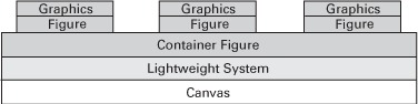
Without question, the most important class in Draw2D is the Figure, and the majority of our Draw2D discussion will focus on its methods and subclasses. Like an SWT Shell, it must be added to a LightweightSystem in order to provide a basis for the GUI’s appearance. Like an SWT Control, it provides for resizing and relocating, adding Listeners and LayoutManagers, and setting colors and fonts. It also functions like a Composite in SWT, providing methods for adding and removing other Figure objects—children—within its frame. This is shown in figure C.1.
Figure C.1. Class relationships within Draw2D user interfaces
However, unlike Widget and Control objects, you can easily subclass Figures. Their graphical aspects can be represented by a drawing or image. Not only can Figures use separate Listener interfaces, they can also perform the majority of their event handling by themselves. Figures can even initiate specific kinds of events to alert other objects in the GUI.
To add images and drawings to Figures, you need to use instances of the Graphics class. It functions similar to SWT’s GC (graphics context) class, and it provides methods for incorporating graphics in a given area. It also contains many of the same methods as GC, particularly for drawing lines and shapes, displaying images, and working with fonts. However, the Graphics class provides one very different capability: Its objects can be moved, or translated, within the Lightweight-System. This means that when you want to change the position of a graphical component, Draw2D provides its own drag-and-drop capability to translate a Figure to the desired location.
C.1.2. The Flowchart application
UML has long been preeminent in modeling software, but flowcharts are still helpful in depicting sequential operations within a program. Our Draw2D example focuses on drawing a simple flowchart, as shown in figure C.2.
Figure C.2. A simple flowchart. Not much help for complex projects, but always good for nostalgia.
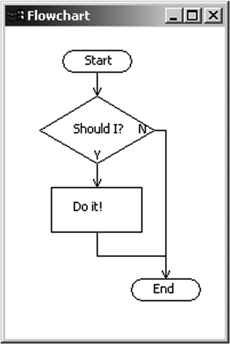
This appendix provides the code needed to create this figure in Draw2D. Appendix D will show you how to build a full flowchart editor based on the Figures we build here.
At the time of this writing, the Draw2D/GEF plug-ins aren’t included in Eclipse and must be downloaded separately. Currently, you can acquire the GEF Software Development Kit (SDK) from www.eclipse.org/gef. This file, which contains the GEF and the Draw2D libraries, can be quickly integrated by placing it in the $ECLIPSE directory and decompressing its contents. Doing so will place the Draw2D/GEF plug-ins in the $ECLIPSE/plugins directory and their features in the $ECLIPSE/features directory.
Because the code in this appendix is lengthy, we recommend that you download our files from the Manning web site (www.manning.com/scarpino). However, if you intend to build your own application, start by adding a com.swtjface.AppB package to the WidgetWindow project. Then, create a classpath variable, Draw2D_LIB, pointing to $ECLIPSE/plugins/org.eclipse.draw2d_x.y.z/draw2d.jar. Add this variable to the project.
The Draw2D library incorporates many classes and capabilities, and this appendix can’t cover every facet of its operation. Therefore, we’ll concentrate on those classes that perform the main work of the toolset. This means investigating the Figure class and its subclasses in greater depth.
C.2. Draw2D Figures
As you’ll see, it takes a fair amount of code to build a Draw2D GUI. However, unlike those in an SWT/JFace GUI, Draw2D elements can be moved and manipulated. These components, including the overall container, are descendents of Draw2D’s main class, Figure. This class contains a number of subclasses that produce the visual aspects of the toolset’s GUI. Figure C.3 shows a small but important subset.
Figure C.3. The Draw2D Figure class and a portion of its subclasses. Many of these play an important role in the flowchart editor presented in appendix D.
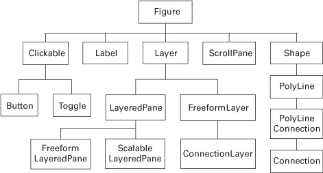
These subclasses will be used extensively in the flowchart editor, particularly those involving Connections and Layers. But first, we need to explore Figures in general.
C.2.1. Figure methods
Like the SWT Control class, the Figure class contains many methods for manipulating its properties. We can’t describe all 137 of them, but we can divide them into four main categories:
- Working with the Figure’s visual aspects
- Event handling
- Keeping track of parents and children
- Managing graphics
If you’ve come this far, then you can probably figure out all you need to know from the Draw2D Javadocs. However, we’ll provide a brief description of these categories here.
Working with a Figure’s visual aspects
The methods in the first category are exactly like those in SWT. These include getting and setting the Figure’s bounds, location, and size. The Figure’s maximum and minimum size can be controlled as well as its border size and visible area. This category also provides methods for changing the Figure’s foreground and background color and getting/setting its focus and visibility parameters.
Event handling in Draw2D
The process of handling events in Draw2D is also similar to SWT, but it provides a few new events and listeners. Unlike SWT, Figures can handle many of their own events. The entire list of listeners and their handling methods is shown in table C.2.
Table C.2. Figure methods for event listening and handling
|
Draw2D listener |
Event-handling method(s) |
|---|---|
| addFocusListener() | handleFocusGained() handleFocusLost() |
| addKeyListener() | handleKeyPressed() handleKeyReleased() |
| addMouseListener() | handleMouseDoubleClicked() handleMousePressed() handleMouseReleased() |
| addMouseMotionListener() | handleMouseDragged() handleMouseEntered() handleMouseExited() handleMouseHovered() handleMouseMoved() |
| addListener() | N/A |
| addAncestorListener() | N/A |
| addFigureListener() | N/A |
| addPropertyChangeListener() | N/A |
The first five methods look and act just like those in SWT, with addListener() receiving untyped Events. But the last three methods are unique to Draw2D.
The addAncestorListener() method responds to any changes to the Figure’s ancestors and functions like the Swing implementation. Similarly, the FigureListener responds whenever the Figure is moved.
The last method, addPropertyChangeListener(), lets you create your own events. This process starts by associating a property, such as a Figure’s location, with a String descriptor. Then, when firePropertyChange() is invoked with this String, any PropertyChangeListeners listening for this property change respond. We’ll revisit this subject in greater depth when we discuss the GEF and its model classes.
Parent and child Figures
SWT and JFace allow components to be included in other components by providing a Composite class. But in Draw2D, any Figure can be a container, and any Figure can be contained. Therefore, Draw2D uses the term parent to refer to the outer graphic and child to refer to the graphic contained within. You create and manipulate these relationships with the methods listed in table C.3.
Table C.3. Parent/child methods of the Figure class
|
Method |
Function |
|---|---|
| add(Figure, Object, int) | Adds a child Figure with the given constraint and List index |
| getChildren() | Returns a List of child Figures |
| getParent() | Returns the Figure’s parent Figure |
| setChildrenEnabled(boolean) | Enables or disables the Figure’ children |
| setConstraint(Figure, Object) | Sets a constraint for the given child Figure |
In SWT, Buttons and Labels add themselves to Composites by identifying parents in their constructors. In Draw2D, a parent Figure uses its add() method to include Figures in its List of children. This method can include an optional constraint (such as the child’s size or location) and/or an index in the parent’s List. Parent Figures can obtain this List with the getChildren() method, and children can access their parent with getParent(). Parents can also enable or disable children with setChildrenEnabled() or alter an aspect of the child with setConstraint().
Managing graphics
Although Draw2D provides a Graphics class that performs most of the duties of SWT’s GC, Figures have a few graphical methods of their own. Not only can they control their display with paint(), they can also use paintBorder() and paintClientArea() to select which section to show. Figures can display their children with paintChildren() or use paintFigure() to only show themselves. There are also a number of repaint() methods available, which work similarly to those in SWT.
Draw2D contains methods for finding information about the user’s selection location. This is different from SWT because Draw2D is particularly concerned with precise mouse movements, whereas an SWT GUI is only concerned about the selected Control. These methods include FindMouseEventAt(), FindFigureAt(), and FindFigureAt().
C.2.2. Using Labels and Clickables
The first Figure subclasses for our investigation are the simplest: Labels and Clickables. These objects look and act similarly to their SWT counterparts, but there are a few interesting concerns that you need to keep in mind.
Labels
Draw2D Labels resemble those of SWT but contain more methods for text measurement and image location. You can measure the parameters of the Label’s String through getTextBounds() and getTextLocation(). Similarly, if the Label is associated with an Image, then getIconBounds() and getIconAlignment() will provide information about the Image.
Clickables
This class, which includes Buttons and Toggles, provides binary information concerning the user’s preferences. Like SWT Buttons, they can be configured with style bits to appear like toggle buttons, checkboxes, or regular pushbuttons. You can also control their selection and add images or text. But there are two main differences between Draw2D Clickables and SWT Buttons. The first is that Clickables can take the appearance of any Draw2D Figure. The second has to do with Clickable event handling.
Draw2D user interfaces are generally more complex than those created with SWT and JFace. Therefore, a Clickable’s state information is managed by a ButtonModel or ToggleModel object. This separates the component’s appearance from its behavior and enables you to develop the two aspects independently. You can also contain these Model objects in a ButtonGroup, which manages multiple Clickables at once.
Clickables update their Model objects by calling fireChangeEvent(), which works like the Figure’s firePropertyChangeEvent(). Clickable properties, such as MOUSEOVER_ PROPERTY and PRESSED_PROPERTY, are represented by constants in the Model class. When they change, the Model may fire a number of Draw2D events or inform its ButtonGroup by default.
Example application
The code in listing C.1 won’t be used in our flowchart editor, but it shows how Draw2D Clickables, Models, and ButtonGroups work together. In this case, we use the CheckBox subclass of Clickable and associate it with a ToggleModel.
Listing C.1. Draw2D_Example.java
package com.swtjface.AppC;

import org.eclipse.swt.widgets.*;
import org.eclipse.draw2d.*;
import org.eclipse.draw2d.Label;
import org.eclipse.draw2d.geometry.*;

public class Draw2D_Example
{
  public static void main(String args[])
  {
    final Label label = new Label("Press a button!");
    Shell shell = new Shell();
    LightweightSystem lws = new LightweightSystem(shell);
    Figure parent = new Figure();
    parent.setLayoutManager(new XYLayout());
    lws.setContents(parent);

    Clickable above = new CheckBox("I'm above!");
    parent.add(above, new Rectangle(10,10,80,20));
    ButtonModel aModel = new ToggleModel();
    aModel.addChangeListener(new ChangeListener()
    {
      public void handleStateChanged(ChangeEvent e)
      {
        label.setText("Above");
      }
    });
    above.setModel(aModel);

    Clickable below = new CheckBox("I'm below!");
    parent.add(below, new Rectangle(10,40,80,20));
    ButtonModel bModel = new ToggleModel();
    bModel.addChangeListener(new ChangeListener()
    {
      public void handleStateChanged(ChangeEvent e)
      {
        label.setText("Below");
      }
    });
    below.setModel(bModel);

    ButtonGroup bGroup = new ButtonGroup();
    bGroup.add(aModel);
    bGroup.add(bModel);
    bGroup.setDefault(bModel);

    parent.add(label, new Rectangle(10,70,80,20));
    shell.setSize(130,120);
    shell.open();
    shell.setText("Example");
    Display display = Display.getDefault();
    while (!shell.isDisposed())
    {
      if (!display.readAndDispatch())
        display.sleep ();
    }
  }
}
As you can see, a Draw2D application is just an SWT Shell with a LightweightSystem and Figures. It’s important to understand that the ChangeListener is created by the button’s Model and responds to any mouse action, including clicks and hovering. Also, because the two Models are added to the ButtonGroup, only one of them can be selected at a time.
In order for the parent Figure to understand the Rectangle constraints of its children, you must configure it with a LayoutManager called XYLayout. We’ll now focus on LayoutManagers and how they enable you to determine how children are arranged within Figures.
C.3. Using LayoutManagers and panes
LayoutManagers, like SWT’s Layout classes, specify how child components should be positioned and sized in a container. This section describes LayoutManager’s subclasses and how you can use them.
In addition, we’ll go over Draw2D’s panes: ScrollPanes, LayerPanes, and their subclasses. Draw2D has no Composite class, but these panes generally serve as background containers for its GUIs. As you’ll see, these window-like classes provide a number of capabilities that make it simple to build graphical editors. We’ll finish this section by creating the first flowchart Figure by extending the Free-formLayeredPane class.
C.3.1. Understanding LayoutManager subclasses
In SWT, containers rely on a default layout policy for their children; but Draw2D demands that you choose a LayoutManager subclass. Two of these, FlowFigureLayout and ScrollBarLayout, are only useful for specific Figures, so we’ll concentrate on three (see table C.4).
Table C.4. LayoutManager subclasses
|
Subclass |
Description |
|---|---|
| AbstractHintLayout | Uses hint constraints to determine the size of the child Figures, calculating one dimension based on a specified value for the other |
| DelegatingLayout | Allows children to set their own size according to a Locator constraint |
| XYLayout | Gives the parent the responsibility for sizing and positioning its children according to a Rectangle constraint |
It’s important to understand that when a parent Figure uses its add() method with a position constraint, its LayoutManager is responsible for interpreting the constraint and setting the child’s location as needed.
We’ll choose the XYLayout for our editor. Now we need a suitable container class: We’ll choose the LayeredPane.
C.3.2. LayeredPanes
Since Draw2D applications can become very complex, a LayeredPane provides many levels for displaying Figures. Using transparent Layers, you can separate the graphical aspects of your GUIs. Different Layers can have different properties, including separate LayoutManagers. This will be important for our editor, because we add not only Figures but also Connections and feedback.
The first step in understanding how LayeredPanes work is learning about Layers. These transparent objects can be manipulated as individual Figures, and the Layer class contains two methods of its own: containsPoint() and findFigureAt(). These objects have fixed boundaries, but the FreeformLayer subclass can be extended in all directions. This is necessary for a graphical editing application whose drawings are larger than the window’s visible region.
A LayeredPane adds new Layers with its add() method, which specifies the Layer object, a key to identify it, and an index representing its position. It can also remove Layers or change their positions in its stack.
By choosing subclasses of LayeredPane, you can increase its capabilities. If you’d like to be able to zoom in on sections of the pane, choose ScalableLayered-Pane. Use FreeformLayeredPane if you’d like to extend the window in all directions. If you want both capabilities, use ScalableFreeformLayeredPane. In our case, we’re only interested in extensibility; listing C.2 shows the FreeformLayered-Pane that we’ll use as the basis of our editor.
Listing C.2. ChartFigure.java
package com.swtjface.AppC;

import org.eclipse.draw2d.*;

public class ChartFigure extends FreeformLayeredPane
{
  public ChartFigure()
  {
    setLayoutManager(new FreeformLayout());
    setBorder(new MarginBorder(5));
    setBackgroundColor(ColorConstants.white);
    setOpaque(true);
  }
}
We configure the FreeformLayeredPane with its appearance constraints, but we don’t add any Layers yet. That will happen later in the editor’s development.
C.3.3. ScrollPanes and Viewports
Before ending our discussion of Draw2D’s panes, we need to briefly mention ScrollPanes. These classes are easy to understand and function by creating Scrollbars on top of another Figure. The bars’ visibility can be configured so that they are always showing, never showing, or shown only when needed.
At any given time, only a section of the ScrollPane can be seen. This visible region is called a Viewport. These work similarly to Layers but provide more methods for controlling size and shape. There is also a FreeformViewport for panes that can be extended in all directions.
Now that we’ve built the primary container for our application, we need to create the shapes that will be added to its diagram. For this, we need to investigate Draw2D’s Graphics class and its drawing capability.
C.4. Using the Graphics class to create Shapes
In SWT, graphic contexts (GCs) can either be created as separate objects or obtained as part of a PaintEvent. But in Draw2D, a Figure can acquire a Graphics object by one of the paint methods described in section C.2.1. The vast majority of the Graphics methods are exactly the same as those in GC; the only important difference is that Draw2D allows a Graphics object to move through its translate() method.
However, Draw2D provides more powerful capabilities for creating and manipulating Shapes. As you’ll see, it has packages of helpful classes for working with geometry and graphs.
C.4.1. Using the Graphics class
As we’ve mentioned, the Graphics methods are nearly identical to those of SWT’s GC. Therefore, in this subsection we’ll create the classes that represent the components shown in figure C.2. To clarify, these three Figures function as follows:
- DecisionFigure—Contains a question. One input, two outputs (Yes or No).
- ProcessFigure—Contains an action to be followed. One input, one output.
- TerminatorFigure—Represents the start or end of the flowchart. If it’s used as a start, only the output should be connected. If it’s used as an end, only the input should be connected.
In each case, the Figure’s size is controlled by a variable called bounds. Its text is set with a message String. These constraints are controlled outside of their Figure classes, so you won’t be able to view them yet.
The code for these classes, including the paintFigure() method that creates the Graphics object, is shown in listings C.3 through C.5.
Listing C.3. DecisionFigure.java
package com.swtjface.AppC;
import org.eclipse.draw2d.*;
import org.eclipse.draw2d.geometry.*;

public class DecisionFigure extends ActivityFigure
{
  FixedAnchor inAnchor, yesAnchor, noAnchor;

  public DecisionFigure()
  {
    inAnchor = new FixedAnchor(this);
    inAnchor.place = new Point(1, 0);
    targetAnchors.put("in_dec",inAnchor);

    noAnchor = new FixedAnchor(this);
    noAnchor.place = new Point(2, 1);
    sourceAnchors.put("no",noAnchor);

    yesAnchor = new FixedAnchor(this);
    yesAnchor.place = new Point(1, 2);
    sourceAnchors.put("yes",yesAnchor);
  }

  public void paintFigure(Graphics g)
  {
    Rectangle r = bounds;
    PointList pl = new PointList(4);
    pl.addPoint(r.x + r.width/2, r.y);
    pl.addPoint(r.x, r.y + r.height/2);
    pl.addPoint(r.x + r.width/2, r.y + r.height-1);
    pl.addPoint(r.x + r.width, r.y + r.height/2);
    g.drawPolygon(pl);
    g.drawText(message, r.x+r.width/4+5, r.y+3*r.height/8);
    g.drawText("N", r.x+7*r.width/8, r.y+3*r.height/8);
    g.drawText("Y", r.x+r.width/2-2, r.y+3*r.height/4);
  }
}
Because of the DecisionFigure’s irregular diamond shape, we need to create a separate Polygon by specifying a series of Points. Thankfully, the ProcessFigure is a Rectangle and is much easier to code.
Listing C.4. ProcessFigure.java
package com.swtjface.AppC;
import org.eclipse.draw2d.*;
import org.eclipse.draw2d.geometry.*;

public class ProcessFigure extends ActivityFigure
{
  FixedAnchor inAnchor, outAnchor;

  public ProcessFigure()
  {
    inAnchor = new FixedAnchor(this);
    inAnchor.place = new Point(1, 0);
    targetAnchors.put("in_proc", inAnchor);

    outAnchor = new FixedAnchor(this);
    outAnchor.place = new Point(1, 2);
    sourceAnchors.put("out_proc", outAnchor);
  }

  public void paintFigure(Graphics g)
  {
    Rectangle r = bounds;
    g.drawText(message, r.x + r.width/4, r.y + r.height/4);
    g.drawRectangle(r.x, r.y, r.width-1, r.height-1);
  }
}
Since the TerminatorFigure contains two arcs on either side, it isn’t nearly as easy to draw as the ProcessFigure. However, its code is easy to understand.
Listing C.5. TerminatorFigure.java
package com.swtjface.AppC;

import org.eclipse.draw2d.*;
import org.eclipse.draw2d.geometry.*;

public class TerminatorFigure extends ActivityFigure
{
  FixedAnchor inAnchor, outAnchor;

  public TerminatorFigure()
  {
    inAnchor = new FixedAnchor(this);
    inAnchor.place = new Point(1, 0);
    targetAnchors.put("in_term",inAnchor);

    outAnchor = new FixedAnchor(this);
    outAnchor.place = new Point(1, 2);
    sourceAnchors.put("out_term",outAnchor);
  }

  public void paintFigure(Graphics g)
  {
    Rectangle r = bounds;
    g.drawArc(r.x + r.width/8, r.y, r.width/4, r.height-1, 90, 180);
    g.drawLine(r.x + r.width/4, r.y, r.x + 3*r.width/4, r.y);
    g.drawLine(r.x + r.width/4, r.y + r.height-1, r.x + 3*r.width/4,
               r.y + r.height-1);
    g.drawArc(r.x + 5*r.width/8, r.y, r.width/4, r.height-1, 270, 180);
    g.drawText(message, r.x+3*r.width/8, r.y+r.height/8);
  }
}
Clearly, there’s a great deal more to these classes than just drawings. The added complexity is present for two reasons. First, these Figures need to be connected to other Figures, which means they need ConnectionAnchors (called FixedAnchors). Second, these Figures will play an important role in the full flowchart editor that we’ll create in appendix D. Many of their methods can’t be explained until then (but they’re worth waiting for!).
Since all these Figures extend from an ActivityFigure, it would be a good idea to show what that is. This superclass contains all the methods common to our DecisionFigure, ProcessFigure, and TerminatorFigure. As you can see from listing C.6, most of its methods keep track of Connections and their anchors.
Listing C.6. ActivityFigure.java
package com.swtjface.AppC;

import org.eclipse.draw2d.*;
import org.eclipse.draw2d.geometry.*;

import java.util.*;

abstract public class ActivityFigure
  extends Figure
{
  Rectangle r = new Rectangle();
  Hashtable targetAnchors = new Hashtable();
  Hashtable sourceAnchors = new Hashtable();
  String message = new String();
  public void setName(String msg)
  {
    message = msg;
    repaint();
  }

  public ConnectionAnchor ConnectionAnchorAt(Point p)
  {
    ConnectionAnchor closest = null;
    long min = Long.MAX_VALUE;
    Hashtable conn = getSourceConnectionAnchors();
    conn.putAll(getTargetConnectionAnchors());
    Enumeration e = conn.elements();
    while (e.hasMoreElements())
    {
      ConnectionAnchor c = (ConnectionAnchor) e.nextElement();
      Point p2 = c.getLocation(null);
      long d = p.getDistance2(p2);
      if (d < min)
      {
        min = d;
        closest = c;
      }
    }
    return closest;
  }

  public ConnectionAnchor getSourceConnectionAnchor(String name)
  {
    return (ConnectionAnchor)sourceAnchors.get(name);
  }

  public ConnectionAnchor getTargetConnectionAnchor(String name)
  {
    return (ConnectionAnchor)targetAnchors.get(name);
  }

  public String getSourceAnchorName(ConnectionAnchor c)
  {
    Enumeration enum = sourceAnchors.keys();
    String name;
    while (enum.hasMoreElements())
    {
      name = (String)enum.nextElement();
      if (sourceAnchors.get(name).equals(c))
        return name;
    }
    return null;
  }

  public String getTargetAnchorName(ConnectionAnchor c)
  {
    Enumeration enum = targetAnchors.keys();
    String name;
    while (enum.hasMoreElements())
    {
      name = (String)enum.nextElement();
      if (targetAnchors.get(name).equals(c))
        return name;
    }
    return null;
  }

  public ConnectionAnchor getSourceConnectionAnchorAt(Point p)
  {
    ConnectionAnchor closest = null;
    long min = Long.MAX_VALUE;
    Enumeration e = getSourceConnectionAnchors().elements();
    while (e.hasMoreElements())
    {
      ConnectionAnchor c = (ConnectionAnchor) e.nextElement();
      Point p2 = c.getLocation(null);
      long d = p.getDistance2(p2);
      if (d < min)
      {
        min = d;
        closest = c;
      }
    }
    return closest;
  }

  public Hashtable getSourceConnectionAnchors()
  {
    return sourceAnchors;
  }

  public ConnectionAnchor getTargetConnectionAnchorAt(Point p)
  {
    ConnectionAnchor closest = null;
    long min = Long.MAX_VALUE;
    Enumeration e = getTargetConnectionAnchors().elements();
    while (e.hasMoreElements())
    {
      ConnectionAnchor c = (ConnectionAnchor) e.nextElement();
      Point p2 = c.getLocation(null);
      long d = p.getDistance2(p2);
      if (d < min)
      {
        min = d;
        closest = c;
      }
    }
    return closest;
  }
  public Hashtable getTargetConnectionAnchors()
  {
    return targetAnchors;
  }
}
We’ll describe these ConnectionAnchors and Connections shortly. But first, we need to address Draw2D’s package for geometry and shapes.
C.4.2. Draw2D geometry and graphs
You’ve seen how Points and Rectangles are used, but Draw2D provides many more classes for incorporating shapes in GUIs. For higher-precision measurements, Draw2D provides PrecisionPoints, PrecisionRectangles, and Precision-Dimensions. It contains Ray objects that function like mathematical vectors and a Transform class to translate, rotate, and scale graphical Points and dimensions.
The org.eclipse.draw2d.graph package contains a number of useful classes for creating and analyzing directed graphs. Along with basic Nodes and Edges, this package also provides a DirectedGraphLayout for arranging them. Graph theory is far beyond the scope of this appendix, but if it interests you, this package should prove helpful.
Draw2D’s Figures aren’t connected by Edges, but by Connection objects. To finish our flowchart diagram, we need to show you how this class operates.
C.5. Understanding Connections
The FixedAnchor class has figured prominently in our code listings so far. These objects (subclasses of AbstractConnectionAnchor) enable you to add lines, or Connections, between two Figures. Because Connections create relationships between components, they’re fundamental in system models and diagrams. However, managing Connections and their ConnectionAnchors can be complicated, so it’s important that you understand how they function.
C.5.1. Working with ConnectionAnchors
ConnectionAnchors don’t have a visual representation. Instead, they specify a point on a Figure that can receive Connections. You add them by identifying the Figure in the ConnectionAnchor’s constructor method. This Figure is called the anchor’s owner, not its parent.
The difficulty in working with anchors isn’t adding them, but placing them appropriately. For this reason, the only method required by the ConnectionAnchor interface is getLocation() (see listing C.7).
Listing C.7. FixedAnchor.java
package com.swtjface.AppC;

import org.eclipse.draw2d.*;
import org.eclipse.draw2d.geometry.*;

public class FixedAnchor
  extends AbstractConnectionAnchor
{
  Point place;

  public FixedAnchor(IFigure owner)
  {
    super(owner);
  }

  public Point getLocation(Point loc)
  {
    Rectangle r = getOwner().getBounds();
    int x = r.x + place.x * r.width/2;
    int y = r.y + place.y * r.height/2;
    Point p = new PrecisionPoint(x,y);
    getOwner().translateToAbsolute(p);
    return p;
  }
}
The getLocation() method is called whenever the owner’s location changes. The Point returned by the method tells the GUI where the anchor should be positioned. In our case, we use getOwner() to obtain the owner’s bounds and a constraint called place. This variable specifies the anchor’s location as a proportion of the owner’s dimensions. This way, if the Figure’s size changes, the anchor will still be positioned properly.
For example, we want the input connection into our DecisionFigure to be located at the top of its bounds and halfway across its width. We set this in our class as follows:
inAnchor = new FixedAnchor(this);
inAnchor.place = new Point(1, 0);
targetAnchors.put("in_dec",inAnchor);
Here, place is set to (1,0) to tell the anchor to be located at 1/2 its width and 0/2 its height, as measured from the top, leftmost corner of the Figure’s enclosing Rectangle. The anchor is then placed in a Hashtable with a String key. This doesn’t mean anything in Draw2D, but it will be important when we use this Figure in the GEF editor.
C.5.2. Adding Connections to the GUI
Working with Connections is easier than dealing with their anchors, because Draw2D takes care of drawing the line. Draw2D’s implementation of the Connection interface is PolylineConnection, which is a connected line. Our subclass of PolylineConnection is PathFigure (see listing C.8).
Listing C.8. LiPathFigure.java
package com.swtjface.AppC;

import org.eclipse.draw2d.*;

public class PathFigure extends PolylineConnection
{
  public PathFigure()
  {
    setTargetDecoration(new PolylineDecoration());
    setConnectionRouter(new ManhattanConnectionRouter());
  }
}
Of course, Connections are more than connected lines. We need to set their source and target Figures, and we can configure their appearance and routing. With regard to appearance, you can add decorations to the start and end of the Connection by calling setSourceDecoration() or setTargetDecoration(). In our case, we create a new PolylineDecoration for the end of the Connection, which looks like a triangle tip.
In addition to decorators, you can add Labels or other Figures to Connections by using a ConnectionEndpointLocator. These objects are created with a Connection object and a boolean value representing whether the Figure should be added at the start or end. Then, setVDistance() tells the new Figure how far away it should be from the Connection, and setUDistance() specifies the distance to the Connection’s source or target.
The Connection’s router refers to the path it takes from one anchor to the next. The four subclasses of AbstractConnectionRouter are listed in table C.5.
Table C.5. AbstractConnectionRouter subclasses
|
Subclass |
Description |
|---|---|
| AutomaticRouter | Positions Connections so that they never intersect, or intersect as little as possible |
| ManhattanConnectionRouter | Positions Connections so that all bends are made with right angles |
| ConnectionRouter.NullConnectionRouter | Positions Connections in a straight line from the source anchor to the target |
| BendpointConnectionRouter | Creates moveable points (Bendpoints) for each bend in the Connection |
As you can see in figure C.2, our PathFigures always bend at right angles; this is because we chose to use the ManhattanConnectionRouter. It’s important to note, though, that if your LayeredPane contains a ConnectionLayer, you can also use it to set the routing.
Now that you understand Draw2D’s Figures and Connections, we’ll combine the two in our final section.
C.6. Putting it all together
We’re nearly ready to add the main class of the diagram. But to allow users to reposition Figures, you need to understand how drag-and-drop works in Draw2D. We’ll also present the FigureFactory class so that you can centralize Figure allocation.
C.6.1. Drag-and-drop in Draw2D
We’ve already mentioned a number of important listeners and events in Draw2D, but none of them involved DragSources, DropTargets, or anything resembling the drag-and-drop capability of SWT. This is because at the time of this writing, Draw2D has yet to incorporate this feature. Therefore, our Dnd class, shown in listing C.9, relies on the Figure’s ability to translate itself according to the distance between its present and future locations.
Listing C.9. Dnd.java
package com.swtjface.AppC;

import org.eclipse.draw2d.*;
import org.eclipse.draw2d.geometry.*;

public class Dnd extends MouseMotionListener.Stub
  implements MouseListener
{
  public Dnd(IFigure figure)
  {
    figure.addMouseMotionListener(this);
    figure.addMouseListener(this);
  }
  Point start;
  public void mouseReleased(MouseEvent e){}
  public void mouseClicked(MouseEvent e){}
  public void mouseDoubleClicked(MouseEvent e){}
  public void mousePressed(MouseEvent e)
  {
    start = e.getLocation();
  }
  public void mouseDragged(MouseEvent e)
  {
    Point p = e.getLocation();
    Dimension d = p.getDifference(start);
    start = p;
    Figure f = ((Figure)e.getSource());
    f.setBounds(f.getBounds().getTranslated(d.width, d.height));
  }
};
Because this class extends MouseMotionListener.Stub, it doesn’t need to add all the methods for a MouseMotionListener. But because it needs to respond to mouse clicks, it implements MouseListener and needs to add all the methods for this interface.
C.6.2. Creating Figures with a FigureFactory
To prevent outside methods from directly invoking constructor methods, the editor uses the factory pattern for its Figures. This is a single class whose static methods create new Figures for insertion into the GUI. The code for the FigureFactory is shown in listing C.10.
Listing C.10. FigureFactory.java
package com.swtjface.AppC;

import org.eclipse.draw2d.IFigure;

public class FigureFactory
{
  public static IFigure createTerminatorFigure()
  {
    return new TerminatorFigure();
  }

public static IFigure createDecisionFigure()
  {
    return new DecisionFigure();
  }

  public static IFigure createProcessFigure()
  {
    return new ProcessFigure();
  }

  public static PathFigure createPathFigure()
  {
    return new PathFigure();
  }

  public static ChartFigure createChartFigure()
  {
    return new ChartFigure();
  }
}
We’ve created all the Figures needed for the flowchart and the factory class that creates them. Now we can add the final executable that combines them.
C.6.3. The Flowchart class
To finish the application, listing C.11 presents the Flowchart class.
Listing C.11. Flowchart.java
package com.swtjface.AppC;

import org.eclipse.swt.widgets.*;
import org.eclipse.draw2d.*;
import org.eclipse.draw2d.geometry.*;

public class Flowchart
{
  public static void main(String args[])
  {
    Shell shell = new Shell();
    shell.setSize(200,300);
    shell.open();
    shell.setText("Flowchart");
    LightweightSystem lws = new LightweightSystem(shell);
    ChartFigure flowchart = new ChartFigure();
    lws.setContents(flowchart);

    TerminatorFigure start = new TerminatorFigure();
    start.setName("Start");
    start.setBounds(new Rectangle(40,20,80,20));
    DecisionFigure dec = new DecisionFigure();
    dec.setName("Should I?");
    dec.setBounds(new Rectangle(30,60,100,60));
    ProcessFigure proc = new ProcessFigure();
    proc.setName("Do it!");
    proc.setBounds(new Rectangle(40,140,80,40));
    TerminatorFigure stop = new TerminatorFigure();
    stop.setName("End");
    stop.setBounds(new Rectangle(40,200,80,20));

    PathFigure path1 = new PathFigure();
    path1.setSourceAnchor(start.outAnchor);
    path1.setTargetAnchor(dec.inAnchor);
    PathFigure path2 = new PathFigure();
    path2.setSourceAnchor(dec.yesAnchor);
    path2.setTargetAnchor(proc.inAnchor);
    PathFigure path3 = new PathFigure();
    path3.setSourceAnchor(dec.noAnchor);
    path3.setTargetAnchor(stop.inAnchor);
    PathFigure path4 = new PathFigure();
    path4.setSourceAnchor(proc.outAnchor);
    path4.setTargetAnchor(stop.inAnchor);

    flowchart.add(start);
    flowchart.add(dec);
    flowchart.add(proc);
    flowchart.add(stop);
    flowchart.add(path1);
    flowchart.add(path2);
    flowchart.add(path3);
    flowchart.add(path4);

    new Dnd(start);
    new Dnd(proc);
    new Dnd(dec);
    new Dnd(stop);

    Display display = Display.getDefault();
    while (!shell.isDisposed())
    {
      if (!display.readAndDispatch())
        display.sleep();
    }
  }
}
Although the code for this class is long, its operation is easy to understand. After the ChartFigure is added to the LightweightSystem, four component Figures are created and initialized. These components are connected with four PathFigures. After all the Figures are added to the diagram, the code associates a Dnd object with each component.
The diagram we’ve created is more interesting than many of our SWT GUIs, but it leaves much to be desired. We’d like to add and remove Figures and the Connections between them. We want to resize them and set their messages during operation. Finally, we’d like to persist our flowcharts in a file so we don’t have to rebuild them every time we close the application.
All of this is possible, but it’s not easy. If you thought the code in this appendix was involved, you haven’t seen anything yet. In appendix D, we’ll introduce the Graphical Editing Framework.