Chapter 8
Radiation and Antennas
Antenna is a radiator and sensor of EM waves. It is also a transducer and impedance matching device. It can be designed to direct EM energy in desired directions and suppress it in unwanted directions.
The main aim of this chapter is to provide the fundamentals of antennas. They include:
- antenna definition, functions, properties and parameters
- basic antenna elements
- radiation mechanism, radiated power and radiation resistance of current elements, dipoles and monopoles
- directional characteristics of basic elements
- solved problems, points/formulae to remember, objective and multiple choice questions and exercise problems.
8.1 GENERAL SOLUTION OF MAXWELL’S EQUATIONS
The general Maxwell’s equations and retarded potentials are repeated here for the sake of continuity and clarity.
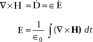
∇ × H = Ḋ + J
∇ × E = − Ḃ
∇.D = ρυ
∇.B = 0
where |
H = magnetic field, (A/m) |
|
D = displacement electric flux density (c/m2) |
|
|
|
J = conduction current density (A/m 2) |
|
E = electric field (V/m) |
|
B = magnetic flux density (wb/m2) |
|
|
From these equations, it is possible to obtain general solutions for E and H fields in terms of potentials and also expressions relating potentials and their sources.
8.2 EXPRESSIONS FOR E AND H IN TERMS OF POTENTIALS
By definition, vector magnetic potential, A is given by
|
∇ × A = B = μH |
or, |
∇ × Ȧ = μḢ |
But |
μḢ = −∇ × E |
|
∇ × Ȧ = −∇ × E |
or, |
∇ × (E + Ȧ) = 0 |
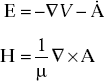
This is true only if (E + Ȧ) represents the gradient of a scalar. Hence,
And we know
or,
Therefore, the general expressions for E and H are given by
Expressions Relating Potentials and Their Sources
Consider |
∇ × A = B |
|
∇ × ∇ × A = μ ∇ × H |
or, |
∇ × ∇ × A = μ ∈ Ė + μJ |
or, |
∇ ∇.A − ∇2 A = μ ∈ [−∇ |
|
= −μ ∈ ∇ |
Curl of A is known and its divergence is not specified.
Helmholtz Theorem
This states that any vector like A has unique meaning only if its curl and divergence are specified.
Hence, the divergence of A is
This is known as Lorentz gauge condition.
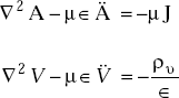
Using Lorentz gauge condition, we get
or, ∇2A − μ ∈ Ȧ = − μJ
Now consider ∇.D = ρυ
or, ∇.E = ρυ/∈
|
∇.(−∇V − Ȧ) = ρυ/∈ |
or, |
∇2 V + ∇.Ȧ = − ρυ/∈ |
|
∇2 V − μ ∈ |
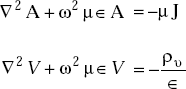
The final expressions are:
For sinusoidal fields, these equations become
8.3 RETARDED POTENTIALS
The potentials for static fields are
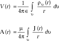
But for time varying fields, they can be written as,
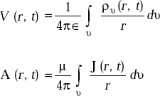
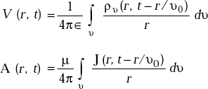
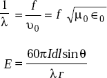
The potentials are usually established due to time varying field only after some amount of propagation time. This propagation time depends on the distance between the point of the potentials from their sources and velocity of propagation of EM fields. As a result, the potentials are retarded by a time, r/ ʋ0. These potentials are known as retarded potentials, and they are expressed as
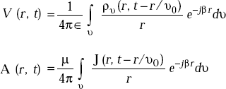
It is well known that a uniform plane wave propagating in rdirection has a phase variation represented by e−jβr. Including this phase factor, the above potentials are given by
8.4 ANTENNA DEFINITION
Antenna or Aerial means the same.
An antenna is defined in the following ways:
- An antenna is a piece of conducting wire or rod with excitation.
- An antenna is a source or radiator of Electromagnetic waves.
- An antenna is a sensor of Electromagnetic waves.
- An antenna is a transducer.
- An antenna is an impedance matching device.
8.5 FUNCTIONS OF AN ANTENNA
- It is used as a transducer, that is, it converts electrical energy into EM energy on the transmitting side and it converts EM energy into electrical energy on the receiving side.
- It is used as an impedance matching device, that is, it matches the transmitter and free space on the transmitting side and it matches free space and the receiver on the receiving side.
- It radiates in the desired directions and suppresses in the unwanted directions.
- It is used as a radiator of EM waves.
- It is used as a sensor of EM waves.
8.6 PROPERTIES OF AN ANTENNA
- It has identical impedance when used for transmitting and receiving purposes.
- It has identical directional characteristics when it is used for transmitting and receiving purposes.
- It has the same effective length when it is used for transmitting and receiving purposes.
These properties can be proved using reciprocity theorem.
8.7 ANTENNA PARAMETERS
- Antenna Impedance, Z a It is defined as the ratio of input voltage to input current, that is,

Z a is a complex quantity and it is written as
Za = Ra + jXaHere, the reactive part Xa results from fields surrounding the antenna. The resistive part, Ra is given by
Ra= R1 + RrHere Rl represents losses in the antenna. Rr is called radiation resistance.
- Radiation Resistance, Rr Rr is defined as the fictitious or hypothetical resistance that would dissipate an amount of power equal to the radiated power.
or,

- Directional Characteristics These are also called radiation characteristics or radiation pattern. These are of two types:
- Field strength pattern It is the variation of the absolute value of field strength as a function of θ.
That is,
 is called field strength pattern.
 - Power pattern It is the variation of radiated power with θ.
That is,
 is called Power pattern.
More generally an antenna radiation pattern is a three dimensional variation of the radiation field.
- Field strength pattern It is the variation of the absolute value of field strength as a function of θ.
- Effective Length of Antenna, (Leff) It is used to indicate the effectiveness of the antenna as a radiator or receiver of EM energy.
Leff of transmitting antenna It is that length of an equivalent linear antenna that has a constant current along its length and which radiates the same field strength as the actual antenna.
Refer Fig. 8.1
.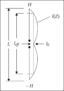
Fig. 8.1 Definition of effective length of transmitting antenna
Leff of transmitting antenna is defined mathematically as
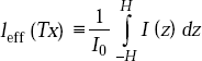
Leff of receiving antenna It is defined as the ratio of the open circuit voltage developed at the terminals of the antenna under the received field strength, E, that is,
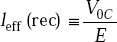
Effective length of an antenna is always less than the actual length.
- Radiation Intensity, (RI) It is defined as the power radiated in a given direction per unit solid angle, that is,
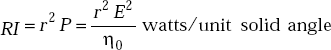
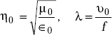
Here
η0 = intrinsic impedance of the medium, (Ω)
r= radius of the sphere, (m)
P= power radiated-instantaneous
E= electric field strength, (V/m)
RI= RI(θ, ϕ) is a function of θ and ϕ
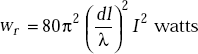
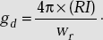
- Directive Gain, (gd) It is defined as the ratio of radiation intensity in that direction to the average radiation intensity, that is,
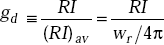
or,
 wr = radiated power
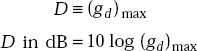
 - Directivity, D It is defined as the ratio of the maximum radiation intensity to the average radiation intensity, that is,
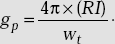
- Power Gain, (g p) It is defined as the ratio of radiated power to the total input power, that is,
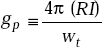
where wt = wr + wl ,
W1 = ohmic losses in the antenna - Antenna Efficiency, (η) It is defined as the ratio of radiated power to the input power, that is,
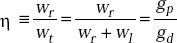
- Effective Area It is defined as

or,

where
WR = received power (watt)
P= power flow per square metre (watts/m2) for the incident wave
- Antenna Equivalent Circuit It is a series Ra , La and Ca circuit (Fig. 8.2).
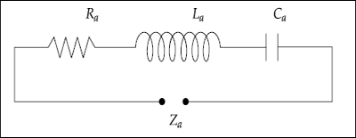
Fig. 8.2 Antenna equivalent circuit
The main difference between the antenna equivalent circuit and an RLCcircuit is that Ra , La and Ca vary with frequency. As a result, the antenna conductance peak appears not at resonant frequency but at a frequency slightly away from fr (Fig. 8.3).
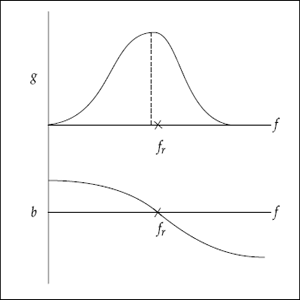
Fig. 8.3 Antenna conductance and susceptance variation
8.8 BASIC ANTENNA ELEMENTS
The basic antenna elements are:
- Alternating current element or Hertzian dipole
- Short dipole
- Short monopole
- Half wave dipole
- Quarter wave monopole
- Alternating Current Element or Hertzian Dipole It is a very short linear antenna in which the current along its length is approximately constant.
- Short Dipole It is a linear antenna whose length is less than
 and the approximate current distribution is triangular.
 - Short Monopole It is a linear antenna whose length is less than
 and the approximate current distribution is triangular.
 - Half Wave Dipole It is a linear antenna whose length is
 and the current distribution is sinusoidal.
 - Quarter Wave Monopole It is a linear antenna whose length is and the current distribution is sinusoidal.
8.9 RADIATION MECHANISM
When a transmitting antenna is excited with an alternating voltage, the initial motion of a wave which is propagated through space is started by the balanced motion of charges in the antenna. The transmitting antenna has characteristics similar to those of a resonant circuit.
When energy is supplied to it, resonant oscillations occur in the antenna and violent variations in charge form an electric vector. The same violent motions of charges create a magnetic field about the antenna in the same manner as a magnetic field expands and collapses about a resonant circuit tank coil.
If energy is continuously applied to the antenna, energy moves away from the antenna into space in the form of EM waves. It may be noted that it is not the original antenna charges themselves that move through space but rather the motion they create. The charges around the antenna are set in motion first and they, in turn, set other charges further separated from the antenna into motion. This disturbance fans out from the antenna into space.
Wave motion of charges forms an electric field and a magnetic field which result from the motion of charges. These electric and magnetic fields are perpendicular to each other. The motion of these fields in the form EM waves has no boundaries and expand spherically. The EM energy density decreases with distance as they propagate.
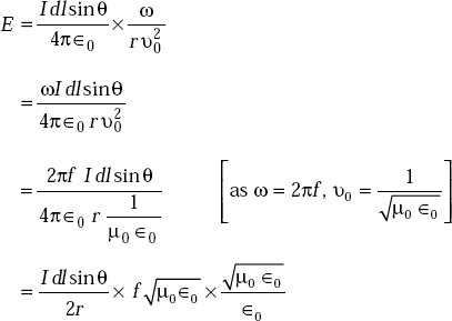
8.10 RADIATION FIELDS OF AN ALTERNATING CURRENT ELEMENT (OR OSCILLATING ELECTRIC DIPOLE)
The concept of an alternating current element, Idlcos ωtis of theoretical interest. But the theory developed for this can be extended to practical antennas. To derive radiation fields of antenna elements including current element, the concept of retarded vector magnetic potential is very useful.
Derivation of radiation fields consists of the following steps:
Write expression for retarded vector magnetic potential.
Write expressions for the components of A in Cartesian coordinates.
Express A in the components of the spherical coordinate system.
Obtain the components of H from μ H = ∇× A.
Obtain the component of E from
 (as J = 0 for space).
Consider an alternating current element at the origin of a spherical coordinate system (Fig. 8.4).
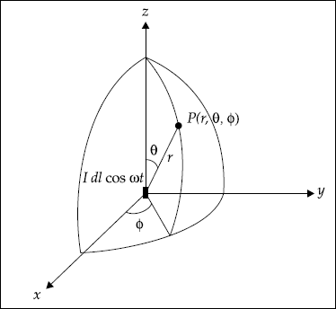
Fig. 8.4 Alternating current element at the origin
The vector magnetic potential, A (r, t) is given by
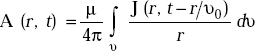
As the element is z-directed, A is also z-directed.
The volume integral in the above equation can be simplified by taking integration over the cross-sectional area of the element and an integration along its length. We know,
and
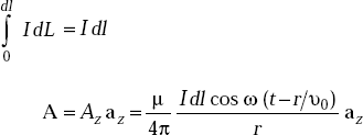
This means A has only z-component and Ax = 0, Ay = 0. Changing Cartesian components into spherical coordinate components, we have
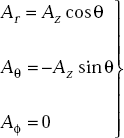
But we know
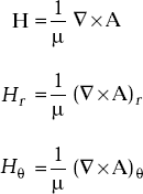
and
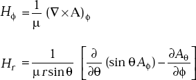
As Aϕ = 0 and Aθ ≠ f(ϕ), Hr = 0.
Similarly,
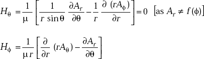
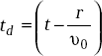
Here
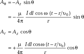
Substituting the expressions of Aθ , Ar and simplifying, we get
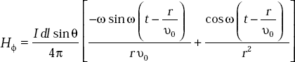
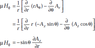
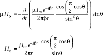
From Maxwell’s first equation, we have
From this, we get
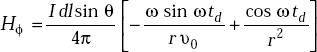
[as H = Hϕaϕ]
and

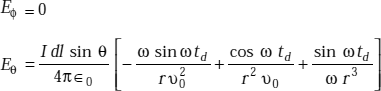
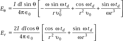
where
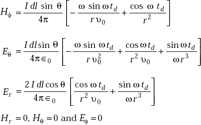
The total field components of an alternating current element are
8.11 RADIATED POWER AND RADIATION RESISTANCE OF A CURRENT ELEMENT
The derivation of the expression for radiated power consists of the following steps:
- Obtain field components as in Section 8.10.
- Obtain expression for radiated power using Poynting vector.
- Obtain average radiated power.
- Obtain total power radiated from

- Identify expression for radiation resistance.
Poynting vector is
P = E ×H xs watts/m2
P θ =−E r H ϕ
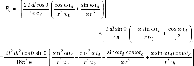
But
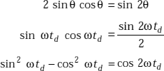
Using these identities, Pθ becomes
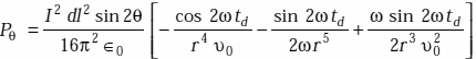
Pθ represents the instantaneous power flow in θ-direction. But the average value of cos 2ωtd or sin 2ωtd over a cycle is zero. Hence (Pθ) av = 0 at any value of r. This means power in θ-direction surges back and forth.
Similarly, Pr = Eθ Hϕ
Using the expressions of Eθ and Hϕ , we get
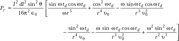
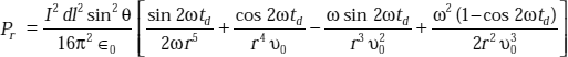
It is obvious that the average value of Pr is
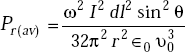
or,
where 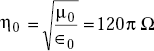
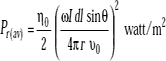
The total power radiated
Pr(av) is independent of ϕ and hence the elemental area ds on the spherical shell is
Now PT becomes

But
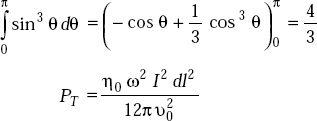
Here Iis the peak value of current.
As

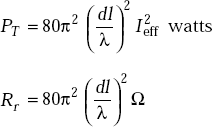
Equation for PT becomes
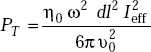
or,
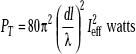
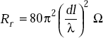
This is in the form of P= I2R. Hence the coefficient of ![]() has the dimensions of resistance and it is called Radiation Resistance.
has the dimensions of resistance and it is called Radiation Resistance.
Radiation Resistance of a Hertzian dipole
8.12 RADIATION, INDUCTION AND ELECTROSTATIC FIELDS
The field components of current elements are:
Hϕ field consists of terms ![]() and
and ![]() .
. ![]() term dominates over
term dominates over ![]() term at points close to the current element. When ris small,
term at points close to the current element. When ris small, ![]() term is called Induction Field.
term is called Induction Field.
On the other hand, ![]() term dominates over
term dominates over ![]() term when ris large. This
term when ris large. This ![]() term is called Radiation Field or distant field or far-field.
term is called Radiation Field or distant field or far-field.
The expression for Eθ consists of three terms, ![]() ,
, ![]() , and
, and ![]() and the expression for Er consists of
and the expression for Er consists of ![]() and
and ![]() terms. The
terms. The ![]() term is called Electrostatic Field.
term is called Electrostatic Field.
In short,
![]() term in E and H fields is called Radiation Field
term in E and H fields is called Radiation Field
![]() term is called Induction Field
term is called Induction Field
![]() term is called Electrostatic Field
term is called Electrostatic Field
If the induction and radiation fields have equal amplitudes, then from the expression of Hϕ , we have
or,
At a distance of ![]() induction and radiation fields have equal amplitudes.
induction and radiation fields have equal amplitudes.
8.13 HERTZIAN DIPOLE
Hertzian dipole is defined as an infinitesimal current element Idlwhich does not exist in real life.
Hertzian dipole is a short linear antenna which, when radiating, is assumed to carry constant current along its length.
As Hertzian dipole and alternating current elements are virtually the same, the radiated power and radiation resistance are given by
8.14 DIFFERENT CURRENT DISTRIBUTIONS IN LINEAR ANTENNAS
The possible current distributions are:
1. Constant current along its length—valid in Hertzian dipole.
2. Triangular current distribution (Fig. 8.5).

Fig. 8.5 Short radiating elements
For triangular current distributions,
3. Sinusoidal current distribution (Fig. 8.6).
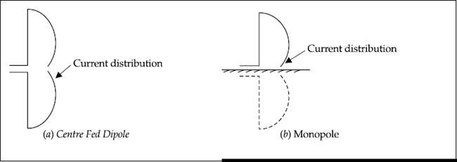
Fig. 8.6 Sinusoidal current distribution in dipole and monopole
4. Exact current distribution—This can be determined using the method of moment technique. The method is briefly presented in Chapter 9.
8.15 RADIATION FROM HALF WAVE DIPOLE
Radiated power by half wave dipole, ![]()
Radiation resistance of half wave dipole, Rr = 73Ω
Proof The proof consists of the following steps:
- Write expressions for the assumed current distribution in the element.
- Obtain expression for vector magnetic potential, A.
- Obtain H from A.
- Obtain E from

- Obtain average radiated power, Pav
- Obtain total power radiated.
- Obtain the value of radiation resistance.
The sinusoidal current distribution is represented by Fig. 8.7.
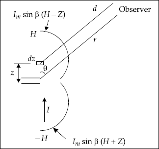
Fig. 8.7 Sinusoidal current distribution
I= Im sin β (H− Z) for z > 0
= Im sin β (H+ Z) for z < 0
Here Im = current maximum
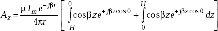
The vector potential at a point, Pdue to the current element I dzis given by
Here d is the distance from the current element to the point P. Let rbe the distance of Pfrom the origin. The total vector potential at Pdue to all current elements is given by
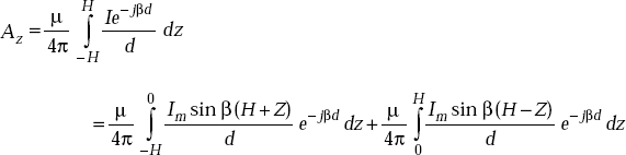
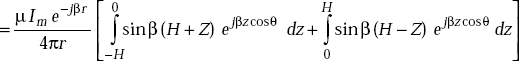
It is of interest here to consider radiation fields. din the denominator can be approximated to r. But in the numerator, dis in the phase term and it is given by
d = r − z cos θ
Now Az becomes

For a half wave dipole
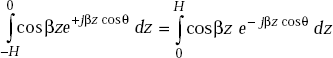
But sinβ (H+ Z) = sinβ cosβz + cos β H sin βz
sinβ (H − Z) = sinβ cosβz − cos β H sinβz
As
sinβ (H+ Z) = sinβ (H− Z) = cosβz
Using these values, Az becomes
But
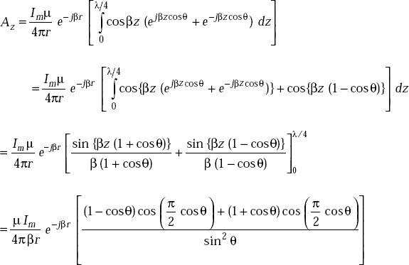
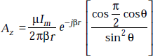
But we have
Hence
We also know that
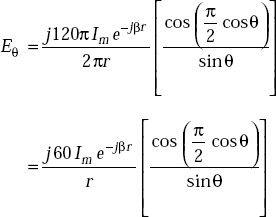
The magnitude of E for the radiation field is
Eθ and Hϕ are in time phase. Hence the maximum value of Poynting vector is
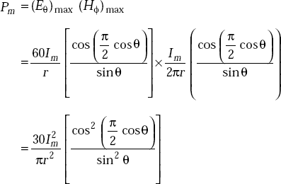
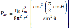
The average value of Poynting vector is one half of the peak value.
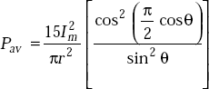
or,
Therefore total power radiated through a spherical surface half wave dipole is
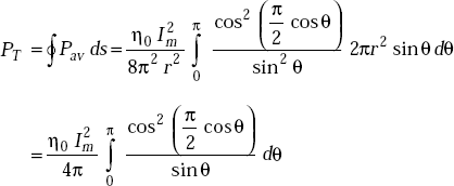
The numerical evaluation of the integral 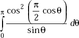 by Simpson’s or the Trapezoidal rule gives a value of 1.218.
As ![]() PT becomes
PT becomes
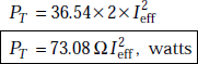
The coefficient of ![]() is nothing but radiation resistance. That is,
is nothing but radiation resistance. That is,
8.16 RADIATION FROM QUARTER WAVE MONOPOLE
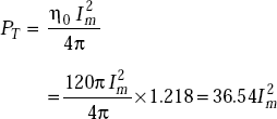
Radiated power of quarter wave monopole, ![]() , watts.
, watts.
Radiation resistance, Rr = 36.5Ω
Proof Consider Fig. 8.8in which a monopole with current distribution is shown.
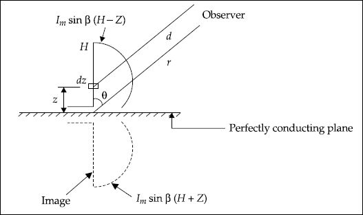
Fig. 8.8 Monopole
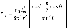
Obtain Pav exactly as described in half wave dipole, that is,
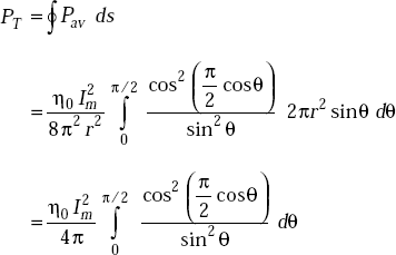
As the monopole is fed by a perfectly conducting plane at one end, it radiates only through a hemispherical surface. Therefore, the total radiated power is
Numerical evaluation of the integral 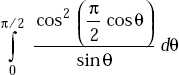 by Simpson’s or the Trapezoidal rule gives a value of 0.609.
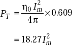
As
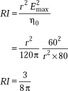
The Radiation resistance,
8.17 RADIATION CHARACTERISTICS OF DIPOLES
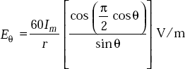
Electric field as a function θ in free space for a dipole of length 2His given by
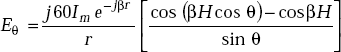
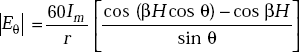
The amplitude of Eθ is
The normalised (Eθ) is
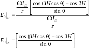
The radiation patterns are the variation of ⎢Eθ ⎢n with θ. These patterns for different lengths of dipole are shown in Fig. 8.9.
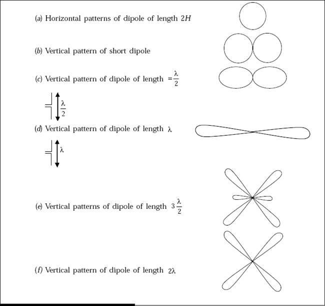
Fig. 8.9 Radiation patterns of dipoles
Problem 8.1 Find the radiation resistance of a Hertzian dipole of length ![]()
Solution The radiation resistance of a Hertzian dipole of length dlis

Problem 8.2 Find the directivity of a current element, Idl.
Soultion The amplitude of electric far-field of a current element is
But
or,
Maximum radiation occurs at θ = π/2
The radiated power of the current element is
If wr is assumed to be 1 watt, then
The maximum radiation intensity is given by
The maximum directive gain, gd (max)
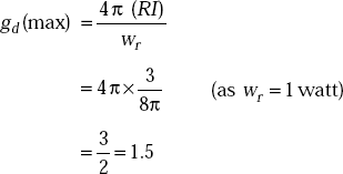
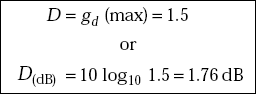
The directivity of current element
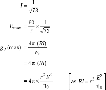
Problem 8.3 Find the directivity of a half wave dipole.
Soultion For a half wave dipole,
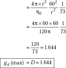
But Wr = 73I2 = watts
For Wr = 1 w,
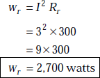
Problem 8.4 An antenna whose radiation resistance is 300Ω operates at a frequency of 1 GHz and with a current of 3 amperes. Find the radiated power.
Soultion Radiated power,
Problem 8.5 What is the effective area of a half wave dipole operating at 500 MHz?
Solution The effective area of an antenna is
As
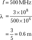
Directivity of half wave dipole is
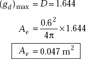
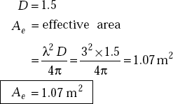
Problem 8.6 Find the effective area of a Hertzian dipole operating at 100 MHz.
Solution As f= 100 MHz
Directivity of the Hertzian dipole,
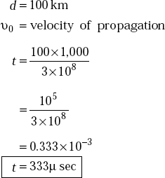
Problem 8.7 An EM wave of 1 GHz is radiated by an antenna to cover a distance of 100 km. Determine the time taken by the wave to travel the above distance.
Solution The time taken by the EM wave is
where
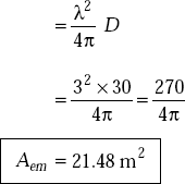
Problem 8.8 The directivity of an antenna is 30 and it operates at a frequency of 100 MHz. Find its maximum effective aperture.
Solution D= 30
f= 100 MHz
Maximum effective aperture
POINTS/FORMULAE TO REMEMBER
Radiation intensity,
 watts/unit solid angle.
Directive gain,
Directivity, D= (gd) max .
Power gain,
Antenna efficiency,

Effective area,
Far-field is represented by
 field term.
Induction field is represented by
 field term.
Radiation resistance of a Hertzian dipole is
Electrostatic field is represented by
 term.
term.The far-field and induction field have equal magnitudes at

Radiation resistance of half wave dipole is 73Ω.
Radiation resistance of quarter wave monopole is 36.5Ω.
Horizontal pattern of vertical dipole is a circle.
Radiated power flow of a vertical dipole is in the radial direction.
1. An antenna is a transducer. |
(Yes/No) |
2. An antenna is a sensor of EM waves. |
(Yes/No) |
3. An antenna acts as an impedance matching device. |
(Yes/No) |
4. Effective length of a wire antenna is always greater than the actual length. |
(Yes/No) |
5. Directive gain = Power gain for an antenna. |
(Yes/No) |
6. The radiation fields are nothing but far-fields. |
(Yes/No) |
7. The radiation pattern of vertical and horizontal dipoles are identical. |
(Yes/No) |
8. The patterns of half wave dipole and quarter wave monopole are identical. |
(Yes/No) |
9. The radiated fields of z-directed half wave dipole consists of Eθ , Er , Hr , Hθ , terms. |
(Yes/No) |
10. The radiated fields of z-directed dipole consists of only Eθ , Er and Hϕ |
(Yes/No) |
11. Effective area of antenna is a function frequency. |
(Yes/No) |
12. Electric and magnetic dipoles have the same physical structure. |
(Yes/No) |
13. Magnetic dipole is a small current loop of wire. |
(Yes/No) |
14. Input and radiation resistances are the same. |
(Yes/No) |
15. The radiation resistance of a current element depends on frequency. |
(Yes/No) |
16. The differential current element is nothing but Hertzian dipole. |
(Yes/No) |
17. Delayed and retarded potentials mean the same. |
(Yes/No) |
18. Jdʋ = IdL |
(Yes/No) |
19. Radiated power of a current element depends on frequency. |
(Yes/No) |
20. The units of scalar and vector magnetic potentials are the same. |
(Yes/No) |
21. Electrostatic field contributes to the radiated power. |
(Yes/No) |
(Yes/No) |
|
23. Electrostatic field does not contribute to radiation power. |
(Yes/No) |
24. Array increases the directivity. |
(Yes/No) |
25. Beam width is decreased by array. |
(Yes/No) |
26. If the number of elements are increased, the beam width is reduced. |
(Yes/No) |
27. Dipole is an omnidirectional antenna. |
(Yes/No) |
28. Isotropic and omnidirectional antennas mean the same. |
(Yes/No) |
29. Dipole and monopole mean the same except in length. |
(Yes/No) |
30. Power gain and directive gain are the same. |
(Yes/No) |
31. Radiation resistance of half-wave dipole is more than that of quarter monopole. |
(Yes/No) |
32. Power gain and efficiency of antennas are the same. |
(Yes/No) |
33. Effective area of receiving antenna depends on frequency. |
(Yes/No) |
34. The effective area of an antenna is independent of the length of the antenna. |
(Yes/No) |
35. The units of radiation intensity are _____ . |
|
36. Directivity is _____ . |
|
37. Efficiency of an antenna is _____ . |
|
38. Efficiency of an antenna in terms of directive and power gains is _____ . |
|
39. Effective area is _____ . |
|
40. The far-field is indicated by the presence of _____ . |
|
41. The induction field is indicated by the presence of _____ . |
|
42. The electrostatic field is indicated by the presence of _____ . |
|
43. The radiation resistance of an isolated half wave dipole is _____ . |
|
44. The radiation resistance of a quarter wave monopole is _____ . |
|
45. The current distribution in a half wave dipole is _____ . |
|
46. The current distribution in alternating current element is _____ . |
|
47. The current distribution in short dipoles is _____ . |
|
|
|
49. The directivity of half wave dipole is _____ . |
|
50. If a current element is x-directed, vector magnetic potential is _____ . |
|
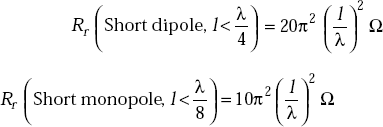
51. Radiation resistance of a short monopole is _____ . |
|
52. Radiation resistance of a short dipole is _____ . |
|
53. At LF and VLF, polarisation often used is _____ . |
|
54. dBi means _____ . |
|
55. dBm means power gain in dB _____ . |
|
56. Antenna used in mobile communications is _____ . |
|
57. If a current element is z-directed, vector magnetic potential is _____ . |
|
58. If vector magnetic potential has only Az , Eϕ is _____ . |
|
59. Radiation resistance of current element is _____ . |
|
60. Radiation resistance of quarter wave monopole is _____ . |
|
61. Directional pattern of a short dipole in the horizontal plane is a _____ . |
|
62. Directional pattern of a horizontal halfwave centre-fed dipole is _____ . |
|
63. Effective length of a dipole is always _____ than the actual length. |
|
64. The directivity in dB of half wave dipole is _____ . |
|
65. The directivity in dB of current element is _____ . |
|
66. Effective area of a Hertzian dipole operating at 100 MHz is _____ . |
|
67. The radiation pattern of a horizontal dipole is of _____ . |
|
68. The radiation pattern of vertical dipole is of _____ . |
|
69. Vector magnetic potential has the unit of _____ . |
|
70. Retarded magnetic potential has the unit of _____ . |
|
71. Radiated power is contributed by _____ only. |
|
72. The radiation resistance of quarter wave dipole is _____ . |
|
|
|
74. The total resistance of an antenna is _____ . |
|
75. Power gain of an antenna is _____ . |
|
76. The antenna of za impedance radiates maximum power when the transmitting line feeding the antenna has an impedance of _____ . |
|
77. Directive gain of Hertzian dipole is _____ . |
|
78. If the signal level is 1 mW, power gain is _____.
- 0 dBm
- 1 dBm
- 10−3dBm
- 10 dBm
79. Whip antenna has a physical length of _____.
- λ/4
- λ/2
- 3λ/2
- λ
80. For a 300 Ω antenna operating with 5 A of current, the radiated power is _____.
- 7,500 W
- 750 W
- 75 W
- 1500 W
Answers
1. Yes |
2. Yes |
3. Yes |
4. No |
5. No |
6. Yes |
7. No |
8. No |
9. No |
10. Yes |
11. Yes |
12. No |
13. Yes |
14. No |
15. Yes |
16. Yes |
17. Yes |
18. Yes |
19. Yes |
20. No |
21. No |
22. Yes |
23. Yes |
24. Yes |
25. Yes |
26. Yes |
27. Yes |
28. No |
29. No |
30. No |
31. Yes |
32. No |
33. Yes |
34. No |
|
|
35. Watts/unit solid angle
36. Maximum directive gain
37. ![]()
38. gp /gd
39. ![]()
40. ![]() term
term
41. ![]() term
term
42. ![]() term
term
43. 73Ω
44. 36.5Ω
45. Sinusoidal
46. Constant
47. Triangular
48. 1.5
49. 1.64
50. x-directed
51. 
52. 
53. Vertical
54. Power gain of the antenna in dB relative to isotropic antenna
55. Compared to 1 mW
56. Whip antenna
57. z-directed
58. Zero
59. 
60. 36.5Ω
61. Circle
62. Figure of eight
63. Less
64. 2.15
65. 1.64
66. 1.07 m2
67. Figure of eight shape
68. Dumbell shape
69. Wb/m
70. Wb/m
71. Far-field only
72. 36.5Ω
73. 73Ω
74. Rr + Rl
75. The product of efficiency and gain
76. Za *
77. 1.5
78. 0 dBm
79. λ/4
80. (a)
MULTIPLE CHOICE QUESTIONS
- Input resistance of an antenna is
- Rr
- Rl
- Rr + Rl
- Rr – Rl
- The radiation resistance of a current element is
- 36.5Ω
- 73Ω


- Horizontal dipole has the directional characteristics of
- circle
- figure of eight
- four lobes
- ellipse
- Retarded vector magnetic potential has the unit of
- wb/m
- V/m
- V/m2
- wb-sec/m
- Radiation resistance of half wave dipole is
- 73Ω
- 36Ω
- 292Ω
- Effective length of half wave dipole is (a) >1 / 2 (b) <1 / 2
- > λ/2
- < λ/2
- 0.55λ
- 0.6λ
- Far-field consists of
 term
term term
term term
term- r term
- Induction field consists of
- term
- term
- term
- r2term
- Radiated power is proportional to
- Rr 2

- I2
- I
- The resonant length of a dipole is
- λ/2
- 0.6λ
- 0.4λ
- 0.35λ
- The length of Whip antenna is


- λ
- For a 300Ω antenna operating with 4 A of current, the radiated power is
- 7,500 W
- 4,800 W
- 480 W
- 75 W
- If the signal level is 1 W, the power gain is
- 1 dB
- 0 dB
- 10 dB
- 10 dBm
- The vector magnetic potential of x-directed half wave dipole is
- x-directed
- y-directed
- z-directed
- θ -directed
- The directivity of current element is
- 1.5
- 1.64
- 1.76
- 2.15
- The directivity of half wave dipole is
- 1.5
- 1.64
- 1.76
- 2.15
- If half wave dipole is operating at one wavelength, its effective area is
- 0.13 m2
- 1.2 m2
- 0.012 m2
- 120 m2
- Radiation resistance of dipole of length 0.11 is
- 2Ω
- 20Ω
- 200Ω
- 73Ω
- Radiation resistance of a monopole of length 0.11 is
- 4Ω
- 2Ω
- 8Ω
- 1Ω
- If the maximum directive gain of an antenna is 2, its directivity is
- 4
- 2
- 1
- 6
Answers
1. (c) |
2. (c) |
3. (b) |
4. (a) |
5. (a) |
6. (b) |
7. (a) |
8. (a) |
9. (c) |
10. (a) |
11. (b) |
12. (b) |
13. (b) |
14. (a) |
15. (a) |
16. (b) |
17. (a) |
18. (a) |
19. (a) |
20. (b) |
EXERCISE PROBLEMS
- The field amplitude due to half wave dipole at 10 km is 0.1 V/m. It operates at 100 MHz. Find the dipole length and its radiated power.
- What is the length of a half wave dipole at frequencies of 10 MHz, 50 MHz and 100 MHz?
- Find the maximum effective area of an antenna at a frequency of 2 GHz when the directivity is 100.
- Obtain the gain of an antenna whose area is 12 m2and operating at a frequency of 6 GHz.
- Find the radiated power of an antenna if a current of 10 amperes exists and its radiation resistance is 32.0Ω.
- What is the radiation resistance of an antenna if it radiates a power of 120 W and when the current in it is 10 amperes.
- Find the directivity, efficiency and effective area of an antenna if its Rr = 80Ω, Rl = 10Ω. The power gain is 10 dB and antenna operates at a frequency of 100 MHz.
- If the transmitting power is 10 KW, find the power density at distances of 10 km, 50 km, 100 km assuming the radiator is isotropic.
- If the current element is z-directed, find the far-field components of H.
- Derive an expression for distant θ-field component of E for a dipole of length L.
-
- Find the current required to radiate a power of 50 W at 60 MHz from 0.1λ Hertzian dipole.
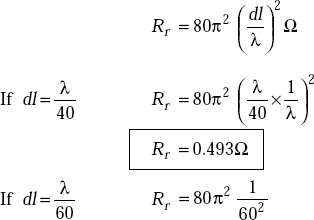
- Determine the radiation resistance of the element.
- Find the radiation efficiency of a Hertzian dipole of length 0.03λ at a frequency of 100 MHz if the loss resistance is 0.01Ω.