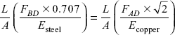
6
Statically Indeterminate Structures
6.1 INTRODUCTION
Generally the trusses are supported on (i) a hinged support and (ii) a roller support. The reaction components of a hinged support are two, and for a roller support reaction component is only one. For any truss, if the number of members making truss is m and the number of joints is j, then for a perfect frame m = 2 j – 3.
The equations of static equilibrium are sufficient to determine internal forces in members of a perfect truss. If members are less than 2j – 3, truss becomes a collapsible truss and if m > (2j – 3), the truss becomes a redundant truss. Equations from statics, ![]() i.e. summation of forces in x- and y-directions, respectively, is zero and summation of moments of forces about any point is zero, are not sufficient to determine internal forces in members of a redundant stress. A unit load method is used to analyze forces in members of a redundant truss.
i.e. summation of forces in x- and y-directions, respectively, is zero and summation of moments of forces about any point is zero, are not sufficient to determine internal forces in members of a redundant stress. A unit load method is used to analyze forces in members of a redundant truss.
Structures used in bridges are generally redundant with multiple degree of redundancy. The study of such structures is beyond the scope of this book; however we will analyze the trusses with single degree of redundancy. Then there are many redundant structures in which strain compatibility condition can be used for analyzing forces in members of trusses or frames.
6.2 ANALYSIS OF REDUNDANT FRAMES WITH STRAIN COMPATIBILITY CONDITION
Let us consider a system of three wires of steel, brass, and aluminium supporting a rigid bar OABCD, which is hinged at end O. A load P is applied at end D of the bar as shown in Figure 6.1(a).
Say internal forces in bars of steel, brass, and aluminium are FA, FB, and FC, respectively. Then from the conditions of static equilibrium:
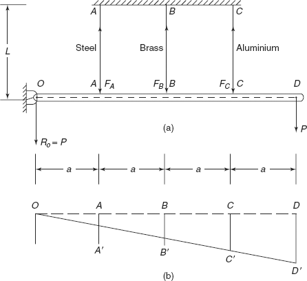
Figure 6.1 (a) A rigid bar supported by three wires (b) Deformations in wires
Moreover, taking moments about O, where RO is reaction at hinged end O,
or
There are four unknowns, i.e. RO, FA, FB, and FC, but only two equations, so conditions of static equilibrium cannot analyze forces in this indeterminate structure. We have to consider the deformation produced in each bar after the application of load, or in other words strain compatibility condition has to be used. The rigid bar is going to take new position OA’ B’ C’ D’ From this diagram
but from the strain compatibility, as is obvious from Figure 6.1(b)
where
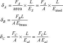
From strain compatibility condition

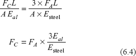
Let us take Esteel = 2Ebrass = 3Eal
So,
Putting these values in Eq. (6.2)
From Eq. (6.1), reaction
R0 reaction is downward.
Example 6.1 A frame ABCD is shown in Figure 6.2. There are three bars AD, BD, and CD hinged at D as shown in Figure 6.2. Bars AD and CD are of copper while bar BD is of steel. Length of middle bar BD is L. Area of cross-section of each bar is the same.
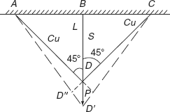
Figure 6.2 Triangular frame under load P
A load P is applied at end D. Determine forces in the three bars. Given Esteel = 2Ecopper.
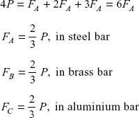
Solution: From the condition of static equilibrium
Due to symmetry FAD = FCD, because both bars are identical and made of copper.
So,
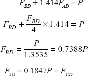
P = FBD + 2FAD cos45°
= FBD + 1.414FAD (ii)
We have to use conditions of strain compatibility. After the application of load, point D moves down to D’ and all the bars are extended.
Extension in AD is D”D’ and extension in BD is DD’.
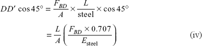
But DD′ cos45° = DD′ (iii)
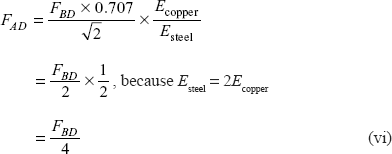
and

where A is area of cross-section.
Using Eq. (iii),
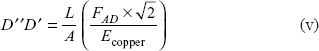
Force
Now from Eq. (ii)
Let us verify the equilibrium of forces at joint D
|
P |
= |
FBD + 1.414 FAD |
|
|
= |
(0.7388 + 1.414 × 0.1847) P |
|
|
= |
(0.7388 + 0.2612) P |
|
|
= |
P |
Exercise 6.1 A rigid bar is suspended by three bars of steel and aluminium as shown in Figure 6.3. The bars are of equal length and equal area of cross-section. A load W is suspended on rigid bar so that the rigid bar remains horizontal after the application of load. Determine forces in aluminium and steel bars.
Esteel = 3Ealuminium
Ans. [Fal = 0.2 W, FS = 0.6 W].
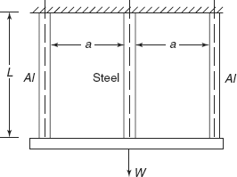
Figure 6.3 Exercise 6.1
6.3 DEGREE OF REDUNDANCY
The total degree of redundancy or degree of indeterminacy of a frame is equal to the number by which the unknown reaction components exceed the condition of equation of equilibrium. The excess members are called redundants.
Total degree of redundancy, T T = m – (2 j – R)
where m = |
total number of members in a frame, |
j = |
total number of joints in frame, and |
R = |
total number of reaction components. |
Following criteria are applied for reaction components at supports of the frame:
- For a roller support—reaction component is 1.
- For a hinged support—reaction components are 2.
- For a fixed support as in cantilever—reaction components are 3.
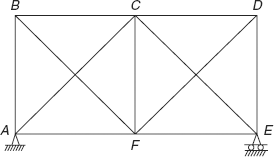
Figure 6.4 Redundant frame
Let us consider the following example:
A frame ABCDEF shown in Figure 6.4 is hinged at end A and roller supported at end E. There are 11 members in frame.
Number of members,
Number of joints,
Reaction components,
R = 2 (for hinged support at A) + 1 (for roller support at E)
= 3
Degree of redundancy,
|
T |
= |
m – (2j – R) |
|
|
= |
11 – (2 × 6 – 3) = 11 – 9 |
|
|
= |
2 |
Similarly, let us consider another frame ABCD, as shown in Figure 6.5, having six members and four joints. Frame is roller supported at A and hinged at end C. Let us determine its degree of redundancy.
Solution: m |
= |
6, number of members |
j |
= |
4, number of joints |
R |
= |
number of reaction components |
|
= |
2 (for hinged end C) + 1 (for roller support A) |
|
= |
3 |
Degree of redundancy
T = m − (2j − R) = 6 −(2×4−3)
= 6 − 5 = 1
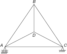
Figure 6.5 Triangular frame
Exercise 6.2 Determine the degree of redundancy for the frames shown in Figures 6.6(a), (b), and (c).
Ans. [For all the above cases, degree of redundancy is 1].
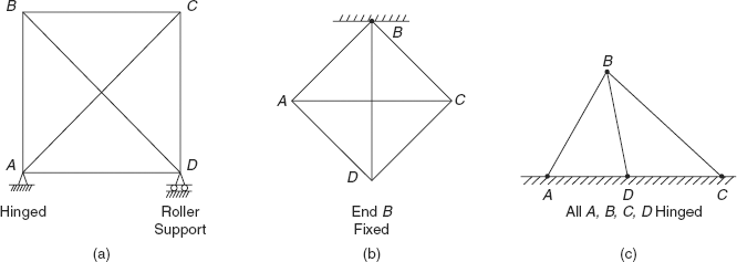
Figure 6.6 Exercise 6.2
6.4 ANALYSIS OF STATICALLY INDETERMINATE TRUSSES
Method of virtual work or unit load method is one of the several methods available for solution of forces in members of an indeterminate truss.
Following relationship is used to calculate the displacement in a member subjected to tensile or compressive load.
Displacement ![]()
where S = |
internal force in truss members due to applied external loads (external loads on truss plus a unit load), |
U = |
axial load in truss members due to unit load applied externally at a point, |
E = |
Young’s modulus of elasticity of member, |
L = |
length of member, and |
A = |
area of cross-section of member. |
We will consider trusses with only single degree of redundancy. Treatment of trusses with more than one redundancy is beyond the scope of this book.
Following steps are followed in order to determine forces in members of indeterminate truss.
- From the indeterminate truss, remove the redundant member so as to obtain statically determinate structure as shown in Figures 6.7(a) and (b).
- Obtain forces in members of statically determinate truss as shown in Figure 6.7(b) by equilibrium equations of statics.
Say these forces are S0 in each member.
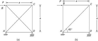
Figure 6.7 (a) Statically indeterminate (b) Member BD removed statically determinate
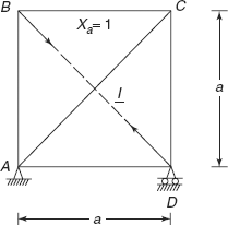
Figure 6.8 Unit load along BD
- Consider the same truss with one redundant member BD cut. Let the force Xa = 1 is applied on this member. Find the forces in members without the external force P (Figure 6.8).
- Net force in each member S = S0 + Xaμa
- Let the relative displacement in redundant member be δa Say the area of cross-section of each member is A and Young’s modulus is E.

or

- Put
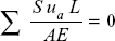 and get the value of Xa
or
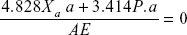
or
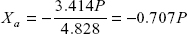
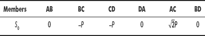
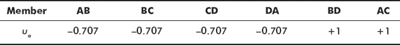
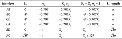
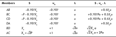
- Forces in members of truss (putting the value of Xa)
Member S Magnitude of S AB−0.707Xa
+ 0.5P
BC−P − 0.707Xa
−0.5P
CD−P − 0.707Xa
−0.5P
DA−0.707Xa
+ 0.5P
BDXa
−0.707P
AC
+ 0.707P
Figure 6.9 shows the forces in the members of the truss.
- Equilibrium of Truss at joints: Let us check the equilibrium of forces at joints of the truss. For that we have to first calculate the reactions.
Taking moments about A,
P× a = RD×a
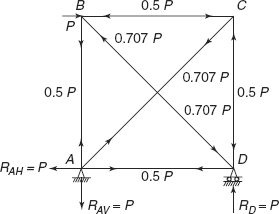
Figure 6.9 Forces in members of truss
Reaction,
Reaction at A,
Reader can verify that the forces at joints A, B, C, and D of truss are balanced and there is equilibrium at each joint.
Exercise 6.3 A redundant frame ABCD is shown in Figure 6.10. Material of all the bars is the same and the area of cross-section is also the same. Determine forces in all the members of the frame.
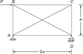
Figure 6.10 Exercise 6.3
Ans. [RDV = 0.5P, RAV = 0.5P ↓, RAH = ![]() ,
,
FAB = 0.25P, FBC = −0.5P, FCD = −0.25P,
FDA = +0.5P, FAC = + 0.559P, FBD = −0.559P]
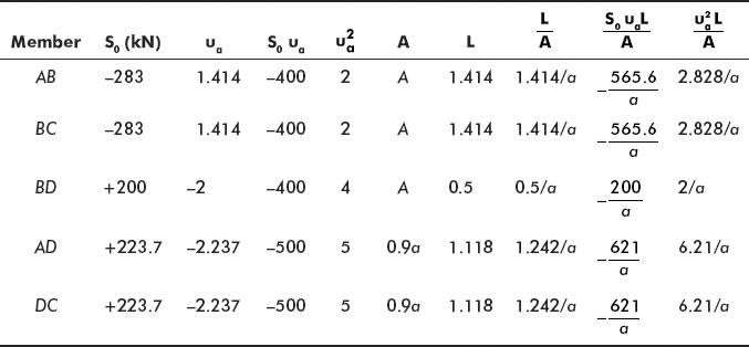
Problem 6.1 For the truss shown in Figure 6.11, determine support reactions and forces in all members. Area of cross-section of members AB, BC, and BD is 25 cm2 and for members AD and DC it is 22.5 cm2.
Material is the same for all the members.
Solution: |
Number of members, |
m = 5 |
|
Number of joints, |
j = 4 |
Both the supports are hinged. So, the number of reaction components,
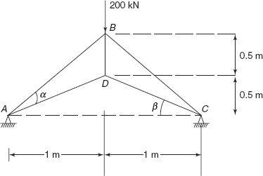
Figure 6.11 Problem 6.1
Degree of redundancy
|
T |
= |
m–(2j–R) |
|
|
= |
5–(2 74–4) |
|
|
= |
1 |
Vertical reactions at A and C
Let us say horizontal reaction at A and C is Xa. Remove Xa from both ends and calculate forces in members. Due to symmetry, we will solve for half the truss (Figure 6.12).

Figure 6.12 Half the truss under load
Angles,
|
α |
= |
tan−l = 45° |
|
β |
= |
tan−1 0.5 = 26.56° |
|
sin α |
= |
cosα = 0.707 |
|
sin β |
= |
0.447 |
|
cos β |
= |
0.894 |
Forces
|
FAB cos45° |
= |
FAD cosβ |
|
FAB × 0.707 |
= |
FAD × 0.894 |
|
FAB |
= |
1.265 FAD |
Now
|
FAD sin β + 100 |
= |
FAB sin 45° |
|
FAD × 0.447 + 100 |
= |
0.707 FAB |
putting the value of
|
FAB |
= |
0.707 × (1.265 FAD) |
|
|
= |
0.894 FAD |
Force,
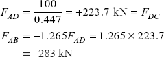
(To have equilibrium of forces at joint A, FAD is tensile and FAB will be compressive as shown).
Joint B
But
283 × 0.707 × 2 = 200 + FBD
400 − 200 = FBD
Force, FBD = +200 kN (tensile)
Now apply the unit load Xa = 1 at ends A and C as shown in Figure 6.13.
F′AD sin β |
= |
F′AB sin 1 |
F′AD × 0.447 |
= |
F′AB × 0.707 |
F′AD |
= |
1.5816 F′AB |
F′AB × 0.707 + 1 |
= |
FAD cos β |
|
= |
0.894F′AD |
|
= |
0.894 × 1.5816F′AB (putting the value of F′Ad) |
|
= |
1.414FJB |
F′AB |
= |
+ 1.414 (tension) |
F′AD |
= |
−1.414 × 1.5816 = −2.237 (comp.) |
Joint B
|
F′BD |
= |
−2 × F′AB × 0.707 = −2 × 1.414 × 0.707 |
|
|
= |
−2 (compressive) |
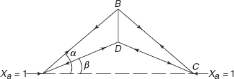
Figure 6.13 Horizontal reactions
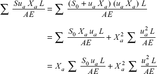
Total force in a member,
S |
= |
S0 + Xaua |
|
= |
Force in a member due to external load after removing redundant reaction + force due to load Xa |
Now,
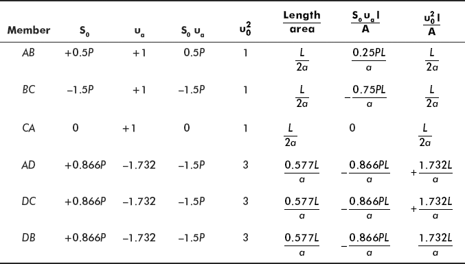
Let us tabulate the values of S, ua, L, A, etc. Please note E is the same for all members.
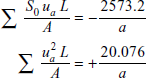
Now
or
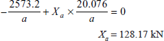
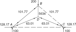
Figure 6.14 Reactions and forces in members
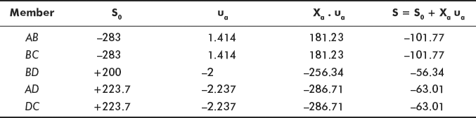
Figure 6.14 shows reactions at supports and forces in all the members. Reader can verify that forces are balanced at all the joints. Please note that in this problem all members are in compression.
Problem 6.2 A triangular truss ABCD is shown in Figure 6.15. It is subjected to a horizontal load P at joint B. Determine support reactions and forces in the members of truss. The cross-sectional area of outer members AB, BC, and CA is twice the cross-sectional area of inner members AD, BD, and CD. The material of all members is the same.
Solution: Taking moments of forces about point A
RCV, reaction
|
|
= |
0.866P↑ |
|
RAV |
= |
0.866P ↓ |
|
RAH |
= |
P as shown. |
Degree of redundancy
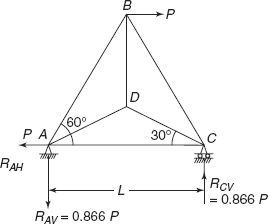
Figure 6.15 Problem 6.2
Number of members,
Number of joints, j = 4
Reactions components,
|
R |
= |
2 (for hinged end) + 1 (roller supported end) |
|
|
= |
3 |
Degree of redundancy,
|
T |
= |
m − (2j − R) |
|
|
= |
6 − (2 ×4 − 3) = 1 |
Let us remove one member AC from the frame, and find forces S0 in members. Member AC is removed (Figure 6.16).
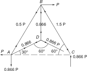
Figure 6.16 Reactions and forces due to unit load
Joint C
|
FBC cos 60° |
= |
FDC cos 30° |
|
FBC × 0.5 |
= |
0.866FDC |
|
FBC |
= |
1.732 FDC |
Moreover,
|
FDC sin 30° + 0.866P |
= |
FBC sin 60 ° |
|
0.5 FDC + 0.866P |
= |
0.866 FBC |
Putting the value of FBC
Force,
|
FBC |
= |
0866P |
|
FDC |
= |
1.732 × 0.866 = 1.5P |
Joint D
so FDC = FDB = FDA = 0.866P (tensil)
Joint A
FAB cos60° + FAD cos30° |
= |
P |
0.5FAB + 0.866 × 0.866P |
= |
P |
0.5FAB |
= |
(P − 0.75P) |
FAB |
= |
0.5P |
Checking for vertical loads.
FAB sin60° + FAD sin30° |
= |
0.5 × 0.866P + 0.866 × 0.5P |
|
= |
0.866P (verified) |
Let us tabulate these values:
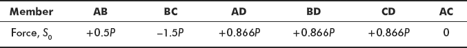
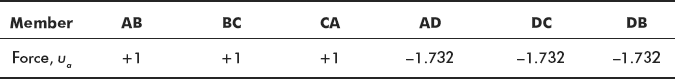
Now consider only Xa = 1 along member AC as shown in Figure 6.17.
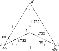
Figure 6.17 Resultant forces in truss
F′AB sin60° |
= |
F′AD sin30° |
F′AB × 0.866 |
= |
F′AD × 0.5 |
F′AD |
= |
1.732F′AB |
F′AD cos30° |
= |
F′AB cos60° + 1 |
F′AD × 0.866 |
= |
0.5F′AB + 1 |
Putting the value of F′AD
1.732 × 0.866F′AB |
= |
0.5F′AB + 1 |
F′AB |
= |
1 = F′BC |
F′AD |
= |
−1.732 (comp) |
|
= |
F′DC = F′DB |
Let us tabulate these ua values also
Length AB = BC = CA = L, area of cross-section 2a

Material of all members is the same. Let us tabulate the different parameters.
Now
or

Resultant Forces in member
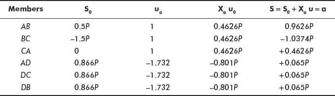
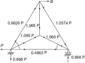
Figure 6.18 Forces in members and reactions

Figure 6.19 Problem 6.3
Reactions and forces in members are shown in Figure 6.18. Reader can verify that the forces are balanced at all joints of the frame.
Problem 6.3 Find the bending moment at any point of a semi-circular arch shown in Figure 6.19. Both the supports are hinged. Flexural rigidity EI is constant throughout.
Solution: For the arch
number of members, m = 1
number of joints, j = 2
number of reaction components,
(both ends are hinged).
Degree of redundancy,
|
T |
= |
m − (2j − R) |
|
|
= |
1 − (2 × 2 − 4) = 1 |
There will be reactions X and ![]() at each end as shown.
at each end as shown.
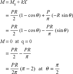
At a particular section a-a, bending moment
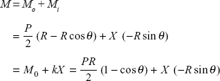
where k = R – sin θ.
Applying the principle of virtual work or unit load method,
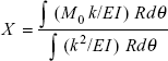
Taking the advantage of symmetrical loading,
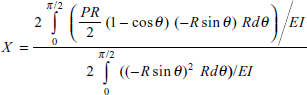
or


Therefore,
Bending moment at any section
Problem 6.4 A rigid bar EF of negligible weight is suspended by four wires A, B, C, and D of the same length, same area of cross-section and same material. A load P is suspended at C as shown in Figure 6.20. Determine forces in four wires.
Solution: From the conditions of static equilibrium,
Moments about point E
or
From the two equations, the values of four forces PA, PB, PC, and PD cannot be determined. We have to take the help of a compatibility condition, i.e. considering the deformation of the bar as shown in Figure 6.20 (b).
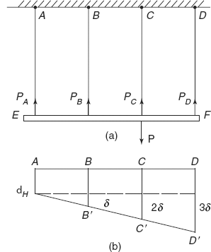
Figure 6.20 Problem 6.4
Deformation in bar A =δA
Deformation in bar B =δA + δ
Deformation in bar C =δA + 2δ
Deformation in bar D =δA + 3δ (as shown)
Rigid bar EF will take the position A’B’C’D’ after the application of load.
Using Hooke’s law, in the elastic region, deformation is directly proportional to load applied.
Say δA ∝ PA (load on wire A)
δ ∝ P′ (load due to additional deformation δ)
So,
|
PB |
= |
PA + P′ |
|
PC |
= |
PA + 2P′ |
|
PD |
= |
PA + 3P′ |
Total reactions
|
|
= |
PA + PB + PC + PD |
|
|
= |
PA + PA + P′ + PA + 2P′ + PA + 3P′ |
|
|
= |
4PA + 6P′ |
|
|
= |
P (iii) |
Putting the values in Eq. (ii)
|
2P |
= |
PA + P′ + 2 (PA + 2P′) + 3 (PA + 3P′) |
|
2P |
= |
PA + 2PA + 3PA + P′ + 4P′ + 9P′ |
|
2P |
= |
6PA + 14P′ |
or P = 3PA + 7P′ (iv)
4PA + 6P′ = 3PA + 7P′
PA = P′ (v)
So,
|
PB |
= |
2P′ |
|
PC |
= |
3P′ |
|
PD |
= |
4P′ |
Total reaction
P′ + 2P′ + 3P′ + 4P′ = P
P′ = 0.10P (vi)
or forces in wire A, |
PA |
= |
P′ = 0.1P |
in wire B, |
PB |
= |
0.2P |
in wire C, |
PC |
= |
0.3P |
in wire D, |
PD |
= |
0.4P |
PRACTICE PROBLEMS
6.1 Determine the degree of redundancy of a frame (semi-circular) hinged at both ends A and B as shown in Figure 6.21.
[Hint: Number of members, m = 1].
Ans. [T = 1].
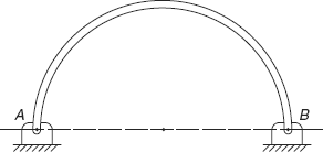
Figure 6.21 Practice problems 6.1
6.2 A statically indeterminate structure ABCD is shown in Figure 6.22.
Ans.
Forces in members
6.3 A triangular frame ABCD is shown in Figure 6.23. It is subjected to a vertical load P at joint B. Determine support reactions and forces in all its members. Material of each member is the same and the area of cross-section of each member is also the same.
Ans.
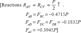
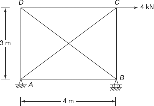
Figure 6.22 Practice problems 6.2
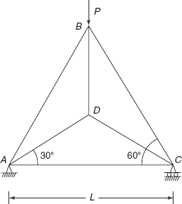
Figure 6.23 Practice problems 6.3
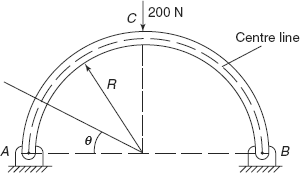
Figure 6.24 Practice problems 6.4
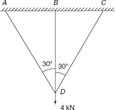
Figure 6.25 Practice problems 6.5
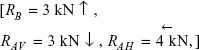
6.4 A semi-circular arch of radius R = 0.5 m is hinged at both ends. It is subjected to a vertical load of 200 N at centre as shown in Figure 6.24. Determine support reactions and write down expression for bending moment at any angle θ. At what angle bending moment is zero?
Ans. [RAV = RBV = 100 N, RAH = RBH = 63.66 N;
M = 50 – 50 cos θ – 31.83 sin θ,
M = 0 at θ = 69° by trial and error].
6.5 A load of 4 kN is suspended from three bars AD, BD, and CD as shown in Figure 6.25. Area of cross-section of each bar is the same and bars are made of the same material.
[Hint: δBD COS 30° = δDC= δDA]
Ans. [FAD= FCD=1.304kN, FBD=1.74kN].
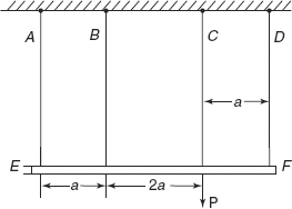
Figure 6.26 Practice problems 6.6
6.6 A rigid bar EF of negligible weight is suspended by four wires A, B, C, and D of the same material, same length and same area of cross-section. A load P is suspended as shown in Figure 6.26. Determine forces in wires A, B, C, and D.
Ans. [0.05P, 0.15P, 0.35P, 0.45P].