3
Fixed Beams
3.1 INTRODUCTION
Fixed or built-in beams are commonly used in building construction because they possess high rigidity in comparison to simply supported beams. When a simply supported beam of length, L, and flexural rigidity, EI, is subjected to a central concentrated load W, the maximum bending moment (BM) in beam is (WL/4), maximum deflection in beam is WI3/48EI, and maximum slope in beam is ±WL2/16EI but if the ends of the same beam are fixed (i.e. built in walls), maximum bending moment is reduced to (WL/8), maximum deflection is reduced to WL3/192EI, and maximum slope is reduced to ±WL2/32EI, If the allowable bending stress for the fixed beam is taken to be the same as for simply supported beam, then the load carrying capacity of the fixed beam is greatly improved. The overall reduction in bending moment, deflection, and slope in the fixed beam is due to the effect of fixing couples provided by the wall in keeping the slope and deflection at the ends to be zero.
During building construction, the beams are cast along with the columns using reinforced cement concrete.
3.2 FIXED BEAM−BENDING MOMENT DIAGRAM
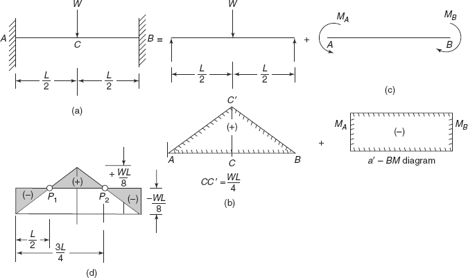
A fixed beam can be considered as equivalent to a simply supported beam plus a beam of the same length, same material, same section subjected to end moments as shown in Figures 3.1 (a), (b), and (c).
A beam ABCD, of length L, fixed at ends A and D, carries loads W1 and W2 at points B and C, respectively, is equivalent to a simply supported beam of length L, simply supported at ends A and D, carrying loads W1 and W2 at B and C, respectively, plus a beam AD of length L, subjected to end moments MA and MD. Considering the beam as simply supported (SS) beam, bending moment diagram can be drawn as shown in Figure 3.2(a). Figure 3.2(b) shows the bending moment diagram of beam due to end moments. Due to end couples, there is convexity in beam, producing negative bending moment throughout. Due to loads and simple supports at ends, there is concavity in the beam producing positive bending moment throughout in the beam. Superimposing the two bending moment diagrams, we get the bending moment diagram for fixed beam as shown in Figure 3.2(c), in which P1 and P2 are points of contraflexure. In the combined bending moment diagram there are positive bending moments and negative bending moments. At P1 and P2 bending moment changes sign from negative to positive and from positive to negative as shown.
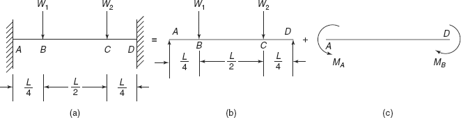
FIGURE 3.1 Fixed beam
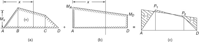
FIGURE 3.2 (a) BM diagram of SS beam (b) BM diagram of end couples (c) BM diagram of fixed beam P1, P2 are point of contraflexure
Let us consider a section XX at a distance of x from end A of the beam.
M, resulting bending moment at section
where Mx |
= |
Bending moment at section when beam is considered as simply supported, and |
M′x |
= |
Bending moment at section due to end moments MA and MD. |
3.3 FIXED BEAM−SUPPORT MOMENTS
Refer to Figures 3.2(a), (b), and (c). Resultant bending moment at any section,
or
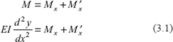
= Bending moment at section when beam is SS + Bending moment at section due to support moments.
Multiplying both sides of Eq. (3.1) by dx, we get
Integrating Eq. (3.2), over the length of the beam
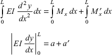
or
= |
Area of the BM diagram of SS beam + area of BM diagram due to support momemts |
where i′D = |
Slope at end D, length is L, and |
i′A = |
Slope at end A, length is zero. |
But beam is fixed for both the ends, so slope at ends
Equation (3.3) becomes
where
or
This Eq. (3.5) shows that the area of BM diagram due to support moments is numerically equal to the area of the BM diagram when beam is SS.
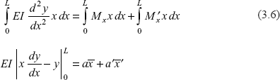
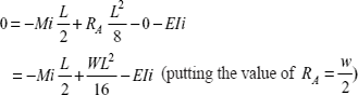
Taking Eq. (3.1) again and multiplying both the sides by x dx, and integrating both the sides over length of beam.
Putting the values of slope and deflection at ends
But in a fixed beam, at the ends, slope and deflection both are zero, therefore,
or
But a = −a′
So, ![]()
i.e. distance of centroid of BM diagram when SS is equal to the distance of the centroid of BM diagram due to support moments from origin A, or from end of the beam
From the a’ diagram, area
(origin at A),
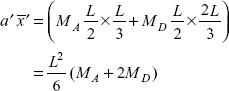
Dividing the diagram into two triangles, we can determine that centroid of area A′AD′ lies at ![]() from A and centroid of triangle ADD′ lies at
from A and centroid of triangle ADD′ lies at ![]() from A (see Figure 3.3). With the help of Eqs (3.5) and (3.9), support moments MA, MD can be worked out.
from A (see Figure 3.3). With the help of Eqs (3.5) and (3.9), support moments MA, MD can be worked out.
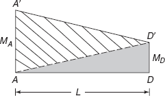
FIGURE 3.3 a′ diagram
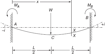
3.4 FIXED BEAM WITH A CONCENTRATED LOAD AT CENTRE
Consider a fixed beam AB of length L, fixed at both ends A and C, carrying a point load W at its centre as shown in Figure 3.4(a). It is equivalent to a simply supported beam AB with central load W and a beam AB subjected to end moments MA and MB. Since the beam is symmetrically loaded, end moments will be equal, i.e.
In SS beam, BM at centre
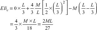
area of a BM diagram,
area of a′ diagram, a′ = MA L = MB L (MA = MB, because of symmetrical loading)
or a′ = −a
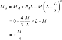
or end moment,
Resultant bending moment diagram is shown in Figure 3.4(a), in which
maximum + ve BM ![]()
maximum (−ve) BM ![]()
Reader may note that maximum bending moment in SS diagram is (WL/4) but when it is fixed at both the ends, maximum bending moment is reduced to 50%, i.e. (WL/8)
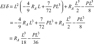
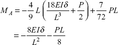
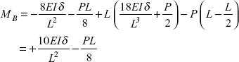
Now let us calculate the maximum deflection in a fixed beam. Again consider a fixed beam AB of length L fixed at both the ends, load at centre is W as shown in Figure 3.5, reactions at ends.
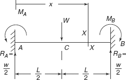
FIGURE 3.5 Fixed beam with central point load
End couples ![]() (as obtained earlier)
(as obtained earlier)
Take a section X − X, at a distance of x from end A, in the portion CB.
Bending moment,
or
Integrating Eq. (3.10), we get
where C1 is constant of integration. (Term in bracket is to be omitted)
At end A,
because end is fixed.
So, constant of integration, C1 = 0
Integrating Eq. (3.11) again, we get
where C2 is another constant of integration. At end A, x = 0, deflection, y = 0, because end is fixed.
So, 0 = 0 + 0 − omitted term + C2, using Macaulay’s method, constant C2 = 0. Finally, the equation for deflection is
Maximum deflection will occur at centre, i.e. at ![]()
Putting this value of x,
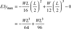
or
Exercise 3.1 A beam of length L = 6 m, fixed at both the ends, carries a concentrated load of 30 kN at its centre. If EI = 7,000 kNm2 for the beam, determine fixing couple at ends and maximum deflection in beam.
Ans. [−22.5 kNm, −4.82 mm].
3.5 FIXED BEAM WITH UNIFORMLY DISTRIBUTED LOAD THROUGHOUT ITS LENGTH
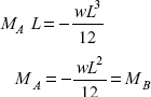
Consider a beam AB, of length L fixed at both the ends A and B, subjected to a uniformly distributed load of intensity w per unit length, throughout the length of the beam as shown in Figure 3.6(a). It is equivalent to a SS beam of length L, subjected to udl, w throughout its length and a beam AB, subjected to end moments MA and MB as shown in Figures 3.6(b) and (c). Since the beam is symmetrically loaded, end moments
When the beam is S.S, bending moment diagram is a parabola with ![]() , maximum bending moment at centre. Area of BM diagram,
, maximum bending moment at centre. Area of BM diagram,
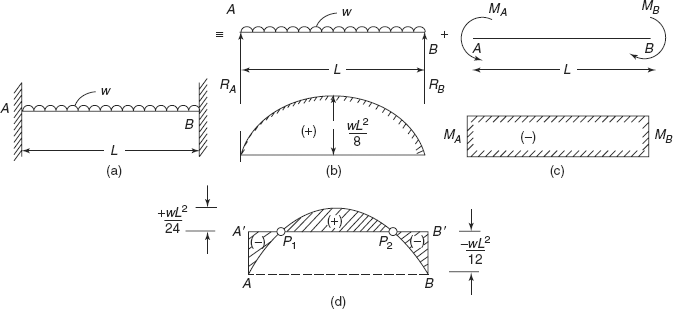
FIGURE 3.6 (a) Fixed beam; (b) a − BM diagram; (c) a′ − BM diagram and (d) BM diagram for fixed beam
area of BM diagram, a′ = MAL = MBL (due to end moments)
Reactions at supports = ![]() (due to symmetrical loading).
(due to symmetrical loading).
The resultant bending moment diagram for fixed beam is shown in Figure 3.6(d), in which P1 and P2 are points of contraflexure. The reader can determine the location of P1 and P2.
Now consider any section X−X at a distance of x from end A as shown in Figure 3.7. Bending moment at section XX is
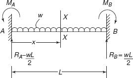
FIGURE 3.7 Fixed beam with u.d.l
or
Integrating Eq. (3.12), we get
at x = 0, end A, slope ![]() , so constant C1 = 0.
, so constant C1 = 0.
Now
Integrating Eq. (3.13) again, we get
At end A, x = 0, deflection y = 0, so constant, C2 = 0
Maximum deflection in the beam will occur at the centre, putting the value of x = ![]() ,
,
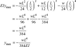
Note that the deflection is reduced to only 20% of the deflection when the beam is simply supported at ends and maximum bending moment in beam is also reduced to ![]() from
from ![]() (in SS beam).
(in SS beam).
Exercise 3.2 A beam 6 m span has its ends built in and carries a uniformly distributed load of 4 kN/m run. Find the (i) end moments, (ii) bending moment at the centre, and (iii) maximum deflection in beam. Given E = 210 GPa, I = 4,800 cm4.
Ans. [(i) −12 kNm, (ii) +6 kNm, (iii) 1.34 mm].
3.6 FIXED BEAM WITH AN ECCENTRIC LOAD
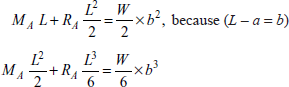
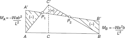
For this problem it is very much time consuming to draw a and a′ BM diagrams and then to determine support reactions and moments. Let us take a fixed beam AB, of length L fixed at both the ends A and B and carrying an eccentric load W at C, at a distance of a from end A (Figure 3.8). Say reactions at A and B are RA and RB and support moments at A and B are MA and MB respectively. There are four boundary conditions at two ends of fixed beam, and we can determine four unknowns RA, RB, MA, and MB.
Consider a section X−X at a distance of x from end A, in portion CB of the beam, bending moment at section XX is
or
Integrating Eq. (3.15), we get
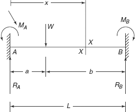
FIGURE 3.8 Fixed beam with eccentric load
At x = 0, end A, slope, ![]() , because of fixed end
, because of fixed end
Constant Cl = 0
Integrating Eq. (3.16), We get
At end A, x = 0, deflection, y = 0, because of fixed end
Constant C2 = 0
So,
At the end B, x = L, both deflection and slope are zero.
Putting x = L in Eqs (3.16) and (3.17)
or
or
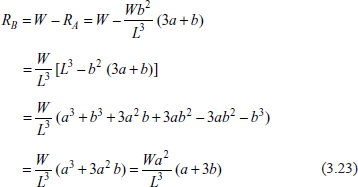
From Eqs (3.20) and (3.21),
Reaction
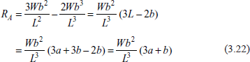
Reaction
Putting the value of RA in Eq. (3.20), we get
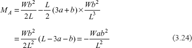
Similarly we can find out that support moment at B,
In Figure 3.8, we have taken a ![]()
Bending moment at point C, when beam is ![]() in BM diagram.
in BM diagram.
Bending moment diagram for fixed beam is A ′ A P1 c′ P2 BB′ as shown in Figure 3.9, where P1 and P2 are points of contraflexure. End moments,
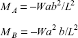
Example 3.1 Let us take numerical values of a and b, say a = 2 m, b = 4 m, L = 6 m, W = 8 kN.
Then
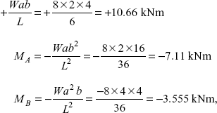
as shown is Figure 3.10
Solution: In a fixed beam with eccentric load, we know that
Reaction,
Moment,
Deflection equation will become
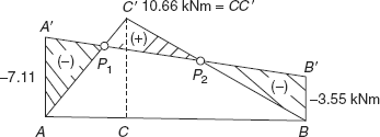
FIGURE 3.10 BM diagram of fixed beam
Let us calculate deflection under the load W, i.e. at x = a
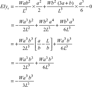
or deflection,
Exercise 3.3 A beam 8 m long fixed at both the ends carries a vertical load of 4 kN at a distance of 3 m from left hand end. Determine: (i) support reactions, (ii) support moments, and (iii) location of points of contraflexure.
Ans. [2.734, 1.266 kN, −4.6875, −2.8175 kNm, 1.66 m and 2.37 m from left hand end].
Example 3.2 A fixed beam AB of length 6 m carries a udl of intensity 6 kN/m over a length AC = 2 m and a point load of 6 kN at point D at a distance of 4 m from A. Using double integration method, determine support reactions, support moments, and draw BM diagram for the beam. What is the deflection at point D of the beam if EI = 1,400 kNm2.
Solution: Figure 3.11 shows a fixed beam AB of length 6 m, carrying udl and concentrated load as shown. There are unknown reactions RA, RB at ends and unknown moments MA, MB as shown. In this problem it is convenient if we take origin at B and x positive towards left, and section XX in portion CA (because udl is in portion CA).
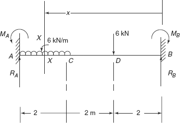
FIGURE 3.11 Example 3.2
Equation of BM
Integrating Eq. (i), we get
So,
Constant C1 = 0
Integrating Eq. (ii), we get
At end B, x = 0, deflection y = 0, because end is fixed.
Constant
Finally, the equation of deflection is
To determine RB, MB, let us consider end A where x = 6 m, both slope and deflection are zero.
Putting this value of x in Eqs (ii) and (iii)
or
or
From these equations, reaction,
Total load on beam |
= |
6 × 2 + 6 = 18 kN |
Reaction, RA |
= |
18 − 5.556 = 12.444 kN |
From Eq. (vi), MB |
= |
9.333 − 3RB = 9.333 − 3 × 5.556 |
|
= |
9.333 −16.668 = −7.335 kNm |
To know bending moment MA, let us put x = 6 in Eq. (i), and putting values of MA, RB also
MA |
= |
−7.335 + 5.556 x 6 − 6 (6 − 2) − 3(6 − 4)2 |
|
= |
−7.335 + 33.336 − 24 −12 |
|
= |
−9.999 kNm. |
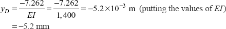
Deflection at D Putting x = 2 m in Eq. (iii)
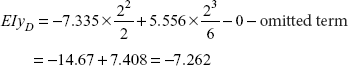
Deflection,
BM Diagram of Fixed Beam
Let us first draw BM diagram of an SS beam with same loads.
Taking moments about A, let us determine reaction R′B
|
6 R′B |
= |
6 × 2 × 1 + 6 × 4 |
|
|
= |
36 |
Reaction, |
R′B |
= |
6 kN |
Reaction, |
R′A |
= |
12 + 6 − 6 |
|
|
= |
12 kN |
Bending Moment
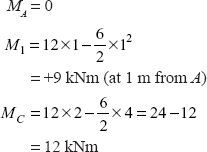
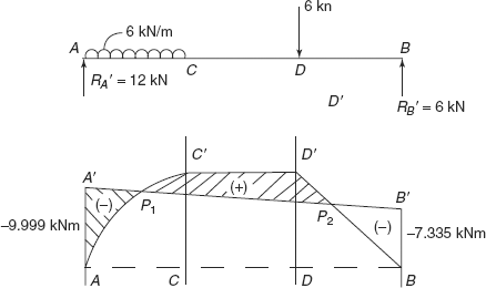
Figure 3.12 AC′D′BDC shows a bending moment diagram of SS beam. Let us draw a′ diagram on this, taking
Figure 3.12 shows the resultant bending moment diagram for fixed beam.
Exercise 3.4 A fixed beam AB of length L carries udl of intensity w over half the length CB as shown in Figure 3.13. Using double integration method, determine support reactions, support moments, and draw its BM diagram.
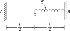
FIGURE 3.13 Exercise 3.4
3.7 EFFECT OF SINKING OF A SUPPORT IN A FIXED BEAM
During the construction of a building or a structure, due to the defect in material or in workmanship, one end of a fixed beam may sink by some amount. This type of sinking is common and may cause unintentional bending moment on the beam. Let us consider that one end of the fixed beam, i.e. support B, sinks by an amount δ, as shown in Figure 3.14(a), say length of beam is L. Level of support B is below the level of support A by δ. Obviously there is no rate of loading on beam, but due to vertical pressure at B, sinking has occurred, therefore,
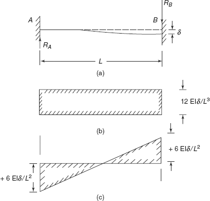
FIGURE 3.14 (b) SF diagram; (c) BM diagram
Integrating Eq. (3.25), we get
Say at x = 0, Reaction = RA, then
Integrating Eq. (3.26), we get
Say at A, x = 0, bending moment is MA, so
Integrating Eq. (3.27), we get
But slope is zero at fixed end, A, i.e. at x = 0
Constant of integration, C3 = 0
So,
Integrating Eq. (3.28), we get
At x = 0, deflection, y = 0,
Constant of integration, C4 = 0
Finally, we have
At end B, x = L, slope, ![]() , deflection, y = − δ
, deflection, y = − δ
Putting these values in Eqs (3.28) and (3.29)
From Eqs (3.30) and (3.31)
or
Putting the values of MA, RA in Eq. (3.27), bending moment at end B
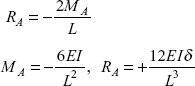
Figures 3.14(b) and (c) show the SF and BM diagrams of a fixed beam, whose one support has sunk. If a fixed beam of length L, carrying concentrated central load W, sinks by an amount δ at right hand support, then support moments will be now ![]() at one end to
at one end to ![]() at the other end.
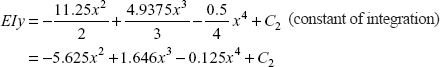
at the other end.
Example 3.3 A beam of 6 m span is fixed at both the ends. Level of right hand support sinks by 3 mm. If EI = 4,500 kNm2 for the beam, determine support reactions and support moments. What is the deflection in the centre of the beam if the beam is subjected to a udl of 3 kN/m.
Solution: Figure 3.15 shows the fixed beam AB, of length 6 m, subjected to udl, w = 3 kN/m
- There is no sinking
Reaction, R′A = Reaction,R′B
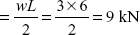
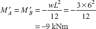
Support moments,
- Support reactions due to sinking
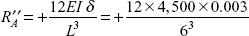
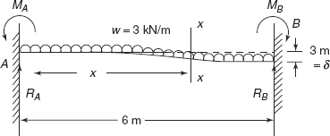
FIGURE 3.15 Example 3.3
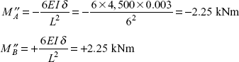
- Support moments due to sinking
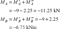
Resulting support reactions,
RB = R′B + R″B = 9 − 0.75 = 8.25 kNResultant support moments,
Deflection at Centre of Beam
Refer to Figure 3.15, consider a section X−X at a distance of x from end A.
Bending moment at section
or
Putting the values of RA, MA, and w.
Integrating Eq. (i), we get
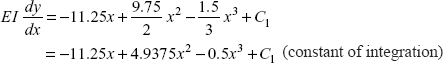
at x = 0, ![]() , constant, C1 = 0
, constant, C1 = 0
Integrating again
at x = 0, = 0, so constant C2 = 0
Finally equation of deflection is
At the centre x = 3 m, putting this value
Exercise 3.5 A beam AB of length 8 m carries a central point load of 8 kN. The right hand support of the beam sinks by 5 mm. If EI = 6,000 kNm2 for the beam, determine support moments, deflection at centre of beam.
Ans. [−10.8125 kNm, −5.1875 kNm, −6.056 mm].
3.8 EFFECT OF ROTATION OF A SUPPORT IN A FIXED BEAM
Due to defective materials or defective construction, if one end of the fixed beam rotates (instead of keeping the slope unchanged), it causes development of support moments. Consider a beam AB, fixed at both the ends but support B rotates by an angle i′B as shown in Figure 3.16 (a).
Now
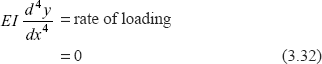
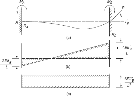
FIGURE 3.16 (b) BM diagram (c) SF diagram
Integrating Eq. (3.32)
at end A, x = 0, shear force RA
Integrating further
At end A, x = 0, moment = MA
Therefore, MA = 0 + C2 or constant of integration = MA
Integrating Eq. (3.34), we get
At x = 0,
So,
Integrating Eq. (3.35), we get
at x = 0, end A, deflection, y = 0.
So,
Finally we have
Let us utilize end condition at B, where x = L,
Using these values in Eqs (3.35) and Eqs (3.36)
From Eq. (3.38), ![]()
Putting this value of MA in Eq. (3.37), we get
Reaction,
Moment,
To maintain equilibrium, RB = RA (but in opposite direction)
Using Eq. (3.34), bending moment at B,
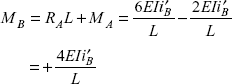
Figure 3.16(b) shows BM diagram, and Figure 3.16(c) shows SF diagram for this fixed beam.
Exercise 3.6 A fixed beam AB of length 7 m rotates at end B by 0.1° in anticlockwise direction. If the beam carries a central load of 8 kN, determine support reactions and support moments. Given EI = 6,500 kNm2.
Ans. [5.39 kN, 2.61 kN, −10.24 kNm, −0.52 kNm].
Problem 3.1 A beam AB of uniform section throughout and of span L is fixed at end A, and carries a central point load P. During loading, support B sinks by δ and rotates by an angle δ/L in anticlockwise direction. Determine the fixing moments at ends if EI is the flexural rigidity of the beam.
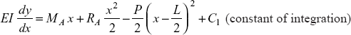
Solution: Figure 3.17 shows a fixed beam AB of span length L, carrying a load P at its centre, support B is below the level of support B by δ, and support B rotates by angle ![]() in anticlockwise direction. Say moments and reaction at A and B are MA, RA; MB and RB, respectively. Now consider a section X−X at a distance x from A in the portion CB of the beam.
in anticlockwise direction. Say moments and reaction at A and B are MA, RA; MB and RB, respectively. Now consider a section X−X at a distance x from A in the portion CB of the beam.
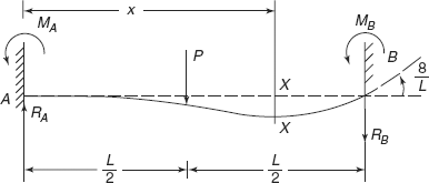
FIGURE 3.17 Problem 3.1
Bending moment at the section
or
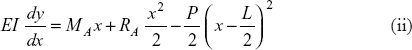
Integrating Eq. (i), we get
At end A, x = 0, slope ![]()
So,
Constant, C1 = 0
Integrating Eq. (ii), again
At end A, x = 0, deflection, y = 0, so
Constant, C2 = 0
Finally the equation is
Putting x = L, at end B, where ![]()
or
Adding Eqs (v) and (vi), we get
or
Substituting the value of MA in Eq. (vi)
Reaction,
Now putting the value of RA in Eq. (viii)
Substituting the values of MA, RA in Eq. (i).
at x = L, Eq. (i) gives BM at end B
Problem 3.2 A beam of span L is fixed at both the ends. A couple M is applied at the beam at a distance of ![]() from left hand end, as shown in Figure 3.18. Determine fixing couples at each support and slope in beam at the point of application of moment.
from left hand end, as shown in Figure 3.18. Determine fixing couples at each support and slope in beam at the point of application of moment.
Solution: Figure 3.18 shows a beam AB of span length L fixed at ends A and B and subjected to moment M at point C, at a distance of ![]() from A. Consider a section X-X at a distance of x from end A, in the portion CB.
from A. Consider a section X-X at a distance of x from end A, in the portion CB.
Bending moment at section is
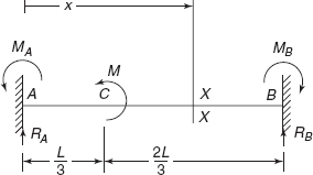
Figure 3.18 Problem 3.2
Integrating Eq. (i), we get
at x = 0, end A, slope ![]() therefore,
therefore,
Constant C1 = 0
Integration Eq. (ii) also
at x = 0, deflection, y = 0, so
Constant C2 = 0
Finally
Using boundary conditions at B, ![]() y = 0 in Eqs (ii) and (iii)
y = 0 in Eqs (ii) and (iii)
or
From these equations
Reaction,
Putting the value of RA in Eq. (vi), we get moment,
To know MB, let us put x = L, and values of MA, RA in Eq. (i)
Slope at C
At
Putting the values in Eq. (ii)
Slope,
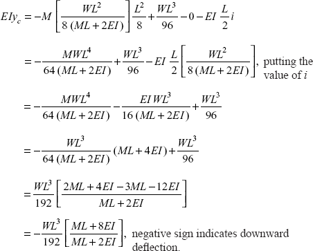
Problem 3.3 A beam of span L carries a load W at its middle. It is so constrained at the ends that when the end slope is i, the restraining couple is Mi. Prove that the magnitude of restraining couple at each end is ![]() (ML + 2EI) and magnitude of central deflection is
(ML + 2EI) and magnitude of central deflection is ![]() .
.
Solution: Figure 3.19 shows a beam of length L, with a concentrated load W at its centre. Beam has a slope −i at A and +i at B. Since the beam is symmetrically loaded, slope at both ends will be equal and opposite, moments MA and MB will be equal, moreover reactions will be equal, i.e.
Slope at A = −i
Moment at A = − Mi
Consider a section X-X at a distance of x from end A, in the portion CB of beam.
Bending moment at section
or
Integrating Eq. (i)
at x = 0, ![]() so
so
Constant of integration,
So,
At the centre of the beam, slope ![]() due to symmetry.
due to symmetry.
Putting ![]() in Eq. (ii)
in Eq. (ii)
So,
Restraining couple at the end
Putting the value of Mi and RA in Eq. (ii), we get
Integrating above, we get
where C2 is another constant of integration.
But x = 0, deflection y = 0, so
Constant, C2 = 0
Finally,
Deflection at the centre, when ![]() putting the value in Eq. (iv)
putting the value in Eq. (iv)
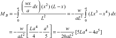
Problem 3.4 A fixed beam of length L carries a linearly increasing distributed load of intensity zero at the left hand end to w up to a distance ‘a’ from the same end. Determine: (i) support reactions, (ii) support moments, if EI is the flexural rigidity of the beam.
Solution: Figure 3.20 shows a fixed beam of length L, carrying a linearly increasing distributed load of intensity zero at end A and w at a distance ‘a’ from A, at section c.
Consider a section X-X, at a distance x from A, Rate of loading at section X-X,
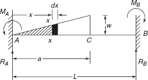
Figure 3.20 Problem 3.4
Elementary load for small length of dx
Considering ![]() as an eccentric load
as an eccentric load
Support moments, dMA
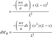
Support moment,
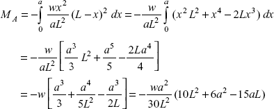
Similarly support moment,
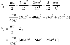
Total load on beam ![]()
Taking moments about point A
or
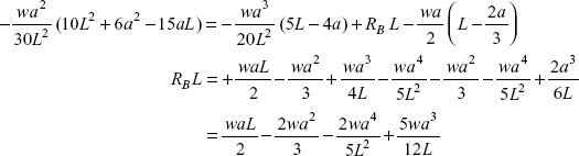
Reaction,
Problem 3.5 A fixed beam of span L carries a udl of intensity w throughout its length. Second moment of area of section of beam is 2I for ![]() from each end and I for the middle
from each end and I for the middle ![]() length. Determine the bending moment at the ends of the beam and sketch the BM diagram.
length. Determine the bending moment at the ends of the beam and sketch the BM diagram.
Solution: The loaded beam is shown in Figure 3.21(a). Because of symmetrical section and symmetrical loading about the centre of the beam, reaction at each end will be equal, i.e.
Moments at ends will be equal, i.e.
Slope at the centre of the beam will be zero.
Let us do the analysis up to the centre of the beam, because it is symmetrical about centre. Consider a section at a distance x from A in the portion CE of the beam, where E is the centre of beam

This equation can be modified as follows
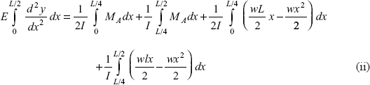
Simplifying Eq. (ii), we get
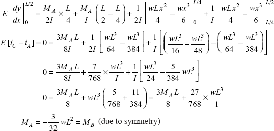
Reader may note the effect of change in section of the beam, if the beam would have been of uniform section throughout, then support moments would have been ![]() .
.
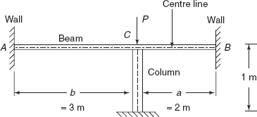
Problem 3.6 A small beam in a bridge deck has to be propped temporarily at a particular point so that the prop can carry half the concentrated load occurring at that point. The beam is 5 m long and has both the ends built in at the same level as shown in Figure 3.22. Concentrated load occurs at 3 m from the left wall. The prop or column is a circular bar, calculate its diameter so that as stated the beam and column carry half the applied load. Second moment of area of beam is 36,000 cm4. Young’s modulus of beam material is double the Young’s modulus of the column material.
Solution: At the section under consideration,
Load is ![]() distance b = 3 m, distance a = 2 m, L = 5 m
distance b = 3 m, distance a = 2 m, L = 5 m
Say Eb = Young’s modulus of beam, then Ib = Moment of inertia of beam section
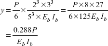
Deflection in beam at the point C
Putting the values,
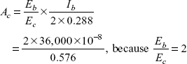
Deflection in column, ![]() length of column = 1 m
length of column = 1 m
But both deflections are the same, so
Area of cross-section of column,
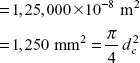
Diameter of column,
Problem 3.7 A horizontal steel bar 60 mm in diameter is rigidly fixed at each end the fixings are 1.2 m apart, as shown in Figure 3.23. A rigid bracket is welded in the middle of the bar at right angles to the axis and in the same horizontal plane. Determine the radius of the arm of the bracket at which a vertical load of 1,200 N can be suspended if the deflection of the load is not to exceed 0.5 mm. Given E = 200 GPa, shear modulus = 80 GPa.
Solution: Bar diameter,
Moment of inertia,
Polar moment of inertia,
J = 2I = 127.24 × 104 mm4
E = 200 × 106 kN/m2
EI = 63.62 × 104 × 10−12 × 200 × 106 = 127.24 kNm2
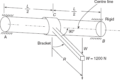
Figure 3.23 Problem 3.7
Deflection in the centre of the bar as fixed beam,
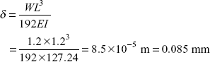
δ′ deflection in the bar due to twisting
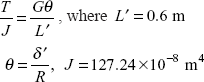
Twisting moment, T = WR = 1.2R kNm
Torque will be equally divided in two portion AC and CB
Torque on AC, ![]()
Using Torsion formula
Putting these values
or
MULTIPLE CHOICE QUESTIONS
- A beam of length L with simply supported ends carries a load W at its centre. The deflection under the load is δ Now both the ends of the beam are fixed, what is the deflection in the centre of this beam.


- None of these
- A beam of length L, fixed at both the ends, carries a udl of intensity w throughout its length, what is the bending moment at the centre of the beam


- None of these
- A beam AB of length L carries a load W at point C, such that
 Both the ends of the beam area are fixed. If EI is the flexural rigidity of the beam, what is deflection at C


- None of these
- A fixed beam of length 6 m carries a concentrated load 6 kN at its centre, what is fixing couple at ends
- −4.5 kNm
- −6 kNm
- −9 kNm
- None of these
- A fixed beam of length L is subjected to a bending moment M at its centre. What is the fixing couple at the ends
- M


- None of these
- A beam of length 4 m, fixed at both the ends, carries a concentrated load 6 kN at its centre. If EI = 2,500 kNm2, what is deflection at the centre of the beam
- 1.0
- 0.8 mm
- 16 mm
- None of these
- A fixed beam of length L sinks at one end by δ. If EI is the flexural rigidity of the beam, what is fixing couple at the ends


- None of these
- A fixed beam AB is of length L, flexural rigidity EI. Its end B rotates by an angle f. What is the reaction produced at end A?


- None of these
Answers
1. (c) |
2. (a) |
3. (c) |
4. (a) |
5. (c) |
6. (b) |
7. (c) |
8. (c). |
|
|
PRACTICE PROBLEMS
3.1 A beam of span length L is fixed at both the ends. It carries a udl of intensity w over middle half length of beam. Determine support reaction, supports moments, deflection at the centre of the beam if EI is the flexural rigidity of beam.
3.2 A beam of span L is fixed at both the ends. Two loads W each are placed at a distance ‘a’ from both the ends. Show that (i) bending moment at centre is ![]() (ii) deflection under either of the loads is
(ii) deflection under either of the loads is ![]() (iii) deflection at centre of beam is
(iii) deflection at centre of beam is ![]() where EI is the flexural rigidity of the beam.
where EI is the flexural rigidity of the beam.
3.3 A fixed beam 6 m long carries point loads of 40 kN each at a distance of 2 m from each end. Determine support reactions, support moments, deflection at the centre of the beam. E = 205 kN/mm2, I = 3,200 cm4.
Ans. [40 kN each, −53.33 kNm at both ends, 10.16 mm].
3.4 A girder 12 m span is fixed horizontally at the ends. A downward vertical load of 80 kN acts on the girder at a distance of 4 m from the left hand end and an upward vertical force of 40 kN acts at a distance of 6 m from the right hand end. Determine end reactions, fixing couples. Draw BM and SF diagrams for the girder.
Ans. [39.26 kN, 0.74 kN; −82.221 kNm, −11.113 kNm].
3.5 A 250 mm × 112.5 mm steel beam with I = 5,000 cm4 is used as a horizontal beam with fixed ends and a clear span of 3 m. Calculate from first principles the load which can be applied at one third of the span if the bending stress is limited to 120 MPa.
Ans. [162 kN].
3.6 A fixed beam AB of length L carries a concentrated load W at mid span. The moment of inertia of the beam from either end to a distance ![]() is I and 2I over the remaining length as shown in Figure 3.24. Calculate the fixing end moments.
is I and 2I over the remaining length as shown in Figure 3.24. Calculate the fixing end moments.
![]()

Figure 3.24 Practice Problem 3.6
3.7 Plot SF and BM diagrams for the fixed beam shown in Figure 3.25, with variable flexural rigidities shown in Figure 3.25. Locate the points of inflexion.
![]()
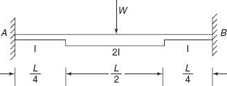
Figure 3.25 Practice Problem 3.7
3.8 A beam AB of flexural rigidity EI and span L carries a udl of intensity w per unit length. It is encastre at A and B but support B settled during the application of the load by an amount δ. Show that if ![]() there is no fixing moment at B.
there is no fixing moment at B.
3.9 A beam of span L is fixed at both the ends. A couple M is applied to the beam at its centre about a horizontal axis at right angle to the beam. Determine the fixing couples at each support and slope at the centre of the beam. EI is the flexural rigidity of the beam.
![]()
3.10 A fixed beam of length L carries a linearly increasing distributed load of intensity zero at the left hand end to w per unit length at right hand end. Determine: (i) support reactions, (ii) support moments. EI is the flexural rigidity of the beam.
Ans. [0.5wL, 0.35wL, −0.033wL2, −0.05wL2]