10
Brittle Coating Technique
10.1 INTRODUCTION
The principle of stress analysis involves the adherence of a thin coating (resin- or ceramic-based) brittle in nature on the surface of a specimen. When the specimen is subjected to external loads, the thin brittle coating cracks under tensile stresses. Strains produced in specimen are transmitted to the coating resulting in coating cracks. From the threshold strain of coating, i.e. minimum strain required to cause the coating to crack, determined through calibration of coating, the stresses in specimen are determined. The behaviour of the coating is quite complicated as it depends on the number of parameters influencing the behaviour of the coating, such as coating thickness, coating temperature, creep in coating during testing, moisture, velocity of air flowing over coating, curing time of the coating, and load-time history; the analysis through brittle coating is more of qualitative nature than of quantitative nature. The use of the coating is limited to identifying the regions of high stresses and regions of low stresses to economize the use of material in component, i.e. low stressed regions of components are identified for weight reduction in component. This technique provides a simple, direct approach for solving large class of industrial problems such as pressure vessels. This technique provides whole field data, and at the same time it is classified as non-destructive. There are various types of coatings as resins based, ceramic based or glass lacquer based brittle coatings. The behaviour of resin-based coatings is viscoelastic (i.e. creep during loading) because in addition to resin it contains plasticizer which controls the sensitivity of the coating.
This technique has been used for (i) the determination of stress concentration in components subjected to various types of loads, (ii) the measurement of thermal and residual strains in components, and (iii) providing whole field data for the magnitude and direction of principal stresses.
This method is based upon the perfect adhesion of a thin coating, brittle in nature on the surface of a component to be analyzed for stresses as shown in Figure 10.1. When the specimen is stressed the surface strains of specimen (at the interface between the specimen and coating) are transmitted to the coating and the coating cracks in a direction perpendicular to maximum tensile principal stress.
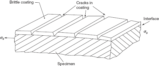
Figure 10.1 Cracks in brittle coating
This method is classified as non-destructive as the coating fails at very low stresses, and specimen is not over-stressed. Common examples of brittle coating are mill scale on hot rolled steel bars, white wash on walls, but the strains required for such coatings to fail by cracking are large.
Ellis in 1941 in United States developed a resin-based commercially available coating. The formulation of this coating is (i) zinc resinate as base, (ii) carbon disulphide as solvent, (iii) dibutyl pthalate as a plasticizer to control the plasticity of the coating or to vary the degree of brittleness of the coating. This coating is known by the trade name of `Stress coat‘. Ceramic coatings which can be employed in high temperature applications have also been developed by the trade name of `All-temp’.
Primary advantages of brittle coating technique are as follows:
- It is nearly a whole field stress analysis technique.
- The technique can be directly applied to a prototype of actual machine member and there is no necessity of any model.
- The technique is applied to the actual machine component in operation and there is no necessity for any simulation.
- Analysis for converting the data into stresses in component is not complicated and only simple mathematical relations are needed.
Disadvantages of the coating are as follows:
- Behaviour of the coating is strongly dependent on temperature and humidity variations during testing.
- Number of variables affects the sensitivity of the coating, therefore the behaviour of the coating has to be properly understood.
- The technique is more qualitative in nature than quantitative.
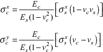
10.2 COATING STRESSES
Coating is sprayed over the surface of the specimen until a thickness of 0.1 to 0.25 mm is built up. Then, coating is dried either at room temperature or at an elevated temperature in a hot air oven. After the coating is completely dried or cured, loads are applied on the sample. Since the coating is very thin, it can be safely assumed that surface strains of the specimen are faithfully transmitted from specimen to coating without any magnification or attenuation. From the stresses in specimen, the stresses in the coating can be obtained. Let us take
![]() ,
, ![]() ; stresses in the specimen in x, y directions
; stresses in the specimen in x, y directions
![]() ,
, ![]() stresses in the coating in x, y directions
stresses in the coating in x, y directions
vc, vs; Poisson’s ratio of coating and specimen
Ec, Es; Young’s modulus for coating and specimen respectively.
Strains in the specimen at the interface abcd as shown in Figure 10.2
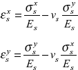
Strains in the coating
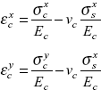
Assuming perfect adhesion between specimen and coating
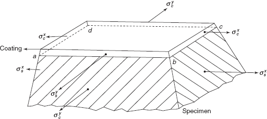
Figure 10.2 Stresses in specimen and coating
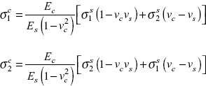
From Eqs (10.1) and (10.2)
Equations (10.3) and (10.4) represent the plane state of stress in the coating (i.e. ![]() = 0) produced in the coating by the plane state of stress in the specimen (i.e.
= 0) produced in the coating by the plane state of stress in the specimen (i.e. ![]() = 0). If the sample is loaded only in x direction, i.e.
= 0). If the sample is loaded only in x direction, i.e. ![]() = 0, then
= 0, then
A brittle coating is generally calibrated by applying uniaxial stress to the specimen which is in the form of cantilever
If ![]() =
= ![]() , threshold strain, that is the minimum strain required to crack the coating, E* = Young’s modulus of the calibrating beam. Then v* Poisson’s ratio of calibrating beam
, threshold strain, that is the minimum strain required to crack the coating, E* = Young’s modulus of the calibrating beam. Then v* Poisson’s ratio of calibrating beam
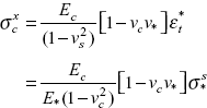
where ![]() = minimum uniaxial stress in the calibrating beam required to crack the coating.
= minimum uniaxial stress in the calibrating beam required to crack the coating.
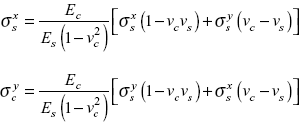
The biaxial stress system in the coating due to uniaxial stress system in the specimen results from the mismatch in the values of Poisson’s ratio between specimen and coating.
Example 10.1 Calculate coating stresses if the specimen stresses are 70 and 40 MPa, assuming
Solution: Specimen stresses are
Coating stresses are
Substituting the value of Es, Ec, vs, and vc, we get
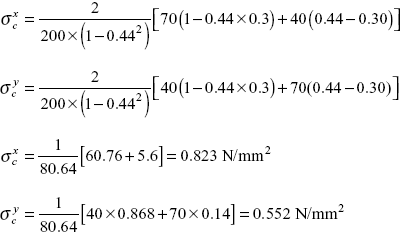
Coating stresses in x and y directions are 0.823 and 0.552 N/mm2, respectively.
Exercise 10.1 Calculate the stresses in steels specimen if coating stresses are
If
Ans. [79.2, 109 N/mm2].
10.3 FAILURE THEORIES
Coating is brittle in nature and for brittle materials, Mohr has developed a theory of failure. In all such brittle materials such as rock, concrete, cast iron, ceramics ultimate compressive strength is much more than the ultimate tensile strength and Mohr theory is the ideal choice for brittle coating. Following cases can be considered for predicting the failure of brittle coating.
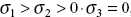
 , both stresses are tensile
 , one tensile and other compressive stress
 both the stresses are compressive.
Case (i) Mohr theory of failure coincides with the maximum principal stress theory of failure
where ![]() is the ultimate tensile strength of the coating.
is the ultimate tensile strength of the coating.
Now,
where ![]() = minimum uniaxial stress in the specimen when the coating cracks perpendicular to
= minimum uniaxial stress in the specimen when the coating cracks perpendicular to ![]()
From expressions (10.5) and (10.6)
Equation (10.7) governs the stresses in the specimen and if ![]() is known then stresses
is known then stresses ![]() and
and ![]() can be worked out
can be worked out
Case (ii) Mohr theory of failure gives the following relationship
where ![]() = ultimate strength of the coating in compression.
= ultimate strength of the coating in compression.
where K is a constant.
Substituting values of ![]() , the relationship (10.8) can be simplified as follows
, the relationship (10.8) can be simplified as follows
where ![]() = minimum uniaxial stress in the specimen when the coating cracks perpendicular to
= minimum uniaxial stress in the specimen when the coating cracks perpendicular to ![]() .
.
Case (iii) According to Mohr theory, coating will fail by cracking if
or
Substituting the values of ![]() and,
and, ![]() we get
we get
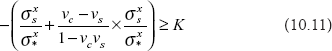
Equation (10.11) can be utilized to determine specimen stresses ![]() and
and ![]() .
.
10.4 CRACK PATTERNS IN BRITTLE COATING
The behaviour of the brittle coating depends upon the nature and magnitude of principal stresses σ1 and σ2. Following three cases will be discussed here:
 , i.e. both the stresses are tensile. Two families of cracks can form depending upon the magnitude of σ1 and σ2. First of all cracks perpendicular to σ1 are developed and as the load on the component increases, cracks perpendicular to σ2 also appear as shown in Figure 10.3. The example of this case is of a thin cylindrical shell subjected to internal pressure. On the surface of the cylinder, hoop stress is more than the axial stress.
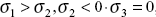 , i.e. one stress is tensile and the other stress is compressive. Only one set of cracks forms which are perpendicular to σ1. Brittle coating is strong in compression, therefore second family of cracks perpendicular to σ2 does not appear; as shown in Figure 10.4.
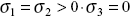 , when both the stresses are the same, stress system is said to be isotropic. Every direction is a principal stress direction. Coating fails by cracking but crack pattern will be random in character, i.e. a craze pattern. This type of crack patterns occur on a spherical shell subjected to internal pressure, where hoop stress occurs equally in all the directions as shown in Figure 10.5.
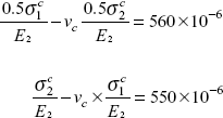
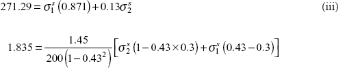
Example 10.2 Brittle coating is applied on the outer surface of a pressure vessel where the pressure inside the vessel is p, first family of cracks appears in coating which are along longitudinal axis of the vessel. By calibration the threshold strain of coating is 560 μ strains. Now pressure inside the vessel is increased to 2p, second family of cracks appears in circumferential direction and threshold strain of coating is 550 μ strains at this stage. Determine stress in coating and stresses in pressure vessel when pressure inside is 2p. Given
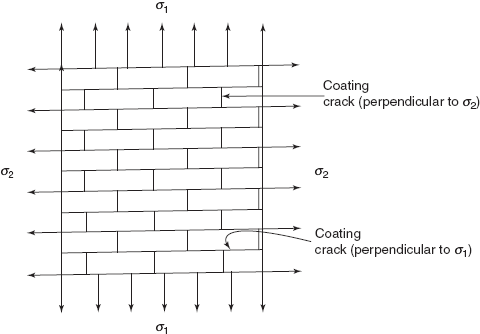
Figure 10.3 Example 10.2
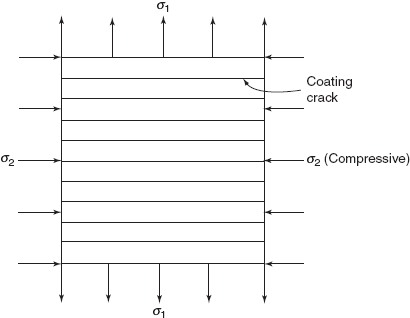
Figure 10.4 Tension
Figure 10.5 Random cracking in coating
Ec = 1.45 × 10+3 N/mm2, vc = 0.43
Es = 200 kN/mm2, vs = 0.30
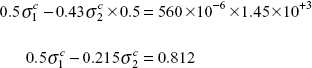
Solution: Say when pressure is 2p, stresses in coating are ![]() ,
, ![]() , in two perpendicular directions, so when pressure is p, stresses would be 0.5
, in two perpendicular directions, so when pressure is p, stresses would be 0.5![]() , 0.5
, 0.5![]()
or
or
Then
or
Stresses in coating
Specimen stress (at 2p)
Putting in values
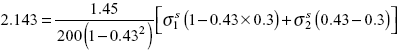
or
or
From these equations ![]() = 282.454 N/mm2
= 282.454 N/mm2
Stress in pressure vessel ![]() = 194.70 N/mm2
= 194.70 N/mm2
Exercise 10.2 A particular specimen of aluminium alloy is coated with Stress coat. At a particular external load first family of cracks appears in coatings, and ![]() = 570 μ strain. Now the load is increased by 50%, a second family of cracks perpendicular to the first family of cracks appears in coating, and
= 570 μ strain. Now the load is increased by 50%, a second family of cracks perpendicular to the first family of cracks appears in coating, and ![]() = 550 μ strain. Determine stresses in coating and stresses in specimen at the second stage.
= 550 μ strain. Determine stresses in coating and stresses in specimen at the second stage.
If
Ec |
= |
1.4GPa, |
Es |
= |
70GPa |
vc |
= |
0.42, |
vs |
= |
0.33 |
Ans. [1.85, 1.55 N/mm2; 81.6, 65.6 N/mm2].
10.5 REFRIGERATION TECHNIQUE
Many components may be highly stressed in a particular region and remaining part of the component may not be sufficiently stressed so as to produce cracks in the coating. These low stressed areas are equally important while designing a component and the thickness of the component can be reduced in such low stressed regions so as to affect weight reduction.
It is possible to obtain cracks in the coating in such low stressed regions by sensitizing the coating and reducing the value of its threshold strain ![]() (at ordinary room temperature). In this technique, first of all, the component is subjected to loads, then cracks develop in some region and the remaining portion is_ uncracked. Now the coating is subjected to a rapid temperature drop while under load. This rapid temperature drop introduces uniform thermal strains (or hydrostatic tension) in the coating. Thermal stresses introduced in the coating are superimposed on the existing stresses in the coating due to applied load on component. Now these isotropic thermal stresses do not have any preferential direction, therefore the direction of resulting cracks is coincident with one of the principal stresses.
(at ordinary room temperature). In this technique, first of all, the component is subjected to loads, then cracks develop in some region and the remaining portion is_ uncracked. Now the coating is subjected to a rapid temperature drop while under load. This rapid temperature drop introduces uniform thermal strains (or hydrostatic tension) in the coating. Thermal stresses introduced in the coating are superimposed on the existing stresses in the coating due to applied load on component. Now these isotropic thermal stresses do not have any preferential direction, therefore the direction of resulting cracks is coincident with one of the principal stresses.
In refrigeration technique, two methods are generally used: (i) ice cold water is sponged over the surface of the coating which has not cracked, but this method does not produce sufficiently high thermal stresses, (ii) by passing a stream of compressed air through a box of dry ice before it is directed onto the surface of the coating.
10.6 LOAD RELAXATION TECHNIQUE
When both the principal stresses are compressive it is not possible to obtain crack patterns in the coating because coating is strong in compression. To circumvent this difficulty, a relaxation technique is used to obtain crack pattern. In this technique, load is applied on the specimen. Then coating is sprayed on the specimen and it is dried while the load is maintained on specimen. When the coating is fully cured, load is released gradually and cracks appear in directions perpendicular to σ1, and/or σ2, depending upon the magnitude of these stresses, as shown in Figure 10.6.
But if one principal stress is tensile and other is compressive, i.e. σ1 > 0, σ2 < 0, two families of cracks are obtained which are superimposed over each other.
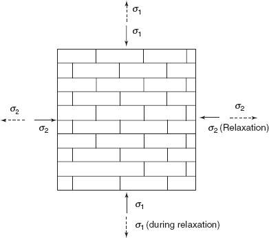
Figure 10.6 Cracks in coating during load relaxation
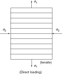
Figure 10.7 Showing cracks perpendicular to σ1 during direct loading
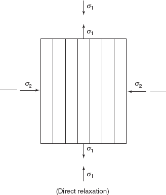
Figure 10.8 Showing cracks perpendicular to σ2 during load relaxation
Figure 10.7 shows the family of cracks for σ1 > 0 and σ2 < 0 during direct loading and Figure 10.8 shows the family of cracks for σ1 > 0 and σ1 < 0 during load relaxation. Duringdirect loading, cracks appear perpendicular to σ1 > 0 and during load relaxation, cracks appear perpendicular to σ2 < 0.
10.7 CRACK DETECTION
For the purpose of stress analysis or to determine stresses in the specimen through coating cracks it is necessary that all coating cracks are located and the loads at which they occur are noted down. These coating cracks are so fine that these are hardly visible through naked eye. These cracks are V-shaped with thickness equal to the coating thickness and width ranging from 0.05 to 0.08 mm. In order to observe these fine cracks visually, a pencil of light is focused on the surface of the crack through oblique incidence as shown in Figure 10.9. Light beam is focused normal to the surface of the crack as shown in the figure.
For stress analysis it is necessary to keep the permanent record of these cracks by taking their photographs and before that making them visible. There are two techniques of crack detection, i.e. (i) statiflux method and (ii) red dye etchant technique.
In the statiflux method, water containing wetting agents (to reduce its surface tension) is spread over the cracked portion of the coating. This wet water flows inside the cracks and fills these cracks, thus making electrical contact with the metallic specimen. Then the surface of the cracked coating is rubbed dry with the help of a facial tissue, so that water is removed from the surface but it remains inside the cracks. Now a talcum powder negatively charged is sprayed (through a special spray gun) on the coating surface. These negatively charged particles of talcum powder are attracted electrically towards the grounded water contained in the fine coating cracks. The powder forms small white mounds over the cracks showing fine white lines of powder over yellow background of resin coating or brown glassy background of ceramic coating. Figure 10.10 shows the white lines of talcum powder over coating surface.
A red dye etchant can also be used for crack detection and increasing the visibility of crack patterns so that cracks can be photographed. The red dye etchant is a mixture of turpentine oil, machine oil, and a red dye (soluble in turpentine oil). The dye mixture is applied on the surface of the cracked coating for approximately one minute. During this time the etchant begins to attack the coating at the surfaces of the cracks, thus making them wider. Now the etchant is wiped out from the surface of the coating and the coating surface is cleaned with the help of an etchant emulsifier which is a soap and water solution. The dye which has penetrated inside the cracks is not removed during this cleaning process. The cracks appear as fine red lines over the surface of brittle coating (yellow in colour) as shown in Figure 10.11.
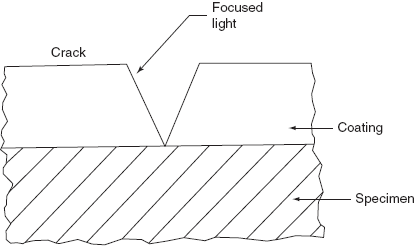
Figure 10.9 Crack detection
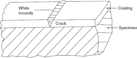
Figure 10.10 White talcum powder in cracks
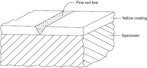
Figure 10.11 Red dye in crack
10.8 TYPES OF BRITTLE COATING
There are various types of resin- and ceramic-based brittle coatings. Magnaflux Corporation of USA markets two different coatings under the trade name of stress coat. Photolastic Corporation markets a coating known as Tens lac. The exact composition of Tens lack is proprietary; however the constituents in the non-flammable coating are similar to those found in strain tec. This coating consists of zinc resinate and calcium resinate dissolved in solvent methylene chloride with oleic acid and the plasticizer is dibutyl pthalate as in stress coat. Stress coat is highly toxic and flammable while strain tec is a new non-flammable, low toxicity coating developed by General Motors. A glass lacquer was developed by Hickson at the Royal Aircraft Establishment in England. This coating consists of a mixture of lithium hydroxide, boric acid, and water. The coating dries at room temperature and is similar to a resin-based coating in many respects.
A ceramic-based coating by the trade name of All-Temp is also marketed by Magnaflux Corporation of USA. All-temp consists of finely ground ceramic particles suspended in a volatile matter. This coating is sprayed onto the specimen.
When the ceramic coating dries in air after spraying, it has a chalk-like appearance and is not suitable for use. The coating is fired at about 1100°F until the ceramic particles melt and coalesce. After firing, the coating has a glass-like appearance and is brown in colour.
Ceramic coating has several advantages over the resin-based coatings such as (i) it is relatively insensitive to minor changes in temperature, (ii) it can be employed at higher temperatures up to 700°F, (iii) it is not influenced by the presence of oil or water which may be present in the test environment, (iv) coating can be used at cryogenic temperatures provided the coating is slowly cooled from room temperature to test temperature. However, ceramic coatings suffer from a number of disadvantages such as (i) high firing temperatures of 1100°F is difficult to obtain, (ii) aluminium, magnesium, plastics, and highly heat-treated steels cannot be used as components for testing, (iii) firing temperature has to be maintained properly as overheating by 25°F will produce bubbles in coating and under heating by 25°F may produce partially cured coatings, (iv) cracks are so fine that visual observation of crack patterns is not possible.
There are various grades of All-temp, marketed by Magnaflux Corporation. The coatings are designed to match the thermal coefficient of expansion of the metal used in fabricating the components.
10.8.1 Resin-based brittle coating
There are three resin-based coatings, i.e. stress coat, strain tec, and tens-lac. After the resin-based coating is sprayed on the specimen, the coating is cured at room temperature or at elevated temperature so that solvent is diffused out of the coating. These resin-based coatings are highly sensitive to change in atmospheric conditions, because the coefficient of thermal expansion of a resin-based coating is an order of magnitude greater than the coefficients of thermal expansion of metals in common use for engineering components. Relative humidity equally affects the behaviour of these coatings. To account for predictable conditions of temperature and humidity, resin-based coatings are available in different grades and a particular grade can be selected for a particular application for specified value of threshold strain under given conditions of temperature and relative humidity. Threshold strain is the minimum value of uniaxial strain required to crack a coating. Selection charts are available for different grades of these coatings.
Variation in temperature during the testing period causes changes in the value of threshold strain for a resin-based coating. Figure 10.12 shows that variation of threshold strain with the increase in the testing temperature. With the increase in the testing temperature, sensitivity of the coating decreases and the threshold strain required to crack the coating is increased. As the temperature increases, residual compressive stress is developed in coating because the coefficient of thermal expansion of coating is much more than the coefficient of thermal expansion of specimen and so more tensile stress is required to crack the coating. For consistent good results, it is necessary that brittle coating laboratory must have at least a temperature-controlled atmosphere. When the tests are performed outdoor, i.e. in the field, it is advisable that weather bureau should be consulted to find when the temperature will be most stable during the day. The test should be conducted in the minimum possible time over which the temperature change is minimum. Moreover, there should be a continuous calibration of the coating for the threshold strain so as to develop a relationship between threshold strain, time, and temperature.
Coatings are sprayed over the specimen with the help of spray guns. For resin-based coatings where carbon disulphide is the solvent, the recommended coating thickness ranges from 0.15 to 0.20 mm and coating where methylene chloride is the solvent, the recommended coating thickness ranges from 0.05 to 0.10 mm. These coatings require 24 hours for curing at room temperature.
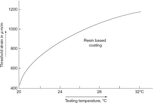
Figure 10.12 Strain vs testing temperature curve
Variation of the thickness of the coating from point to point over the surface of the specimen being analyzed can be a serious source of error. Solvent in the coating is removed by a diffusion process; therefore thicker coatings take more time to dry than thinner coatings. Thicker coatings may not be completely dry. So, the coating exhibits variable sensitivity from point to point. To eliminate such errors, due to partial curing of the coating, coating along with sample is heated in air circulating over at about 28°C for 12 to 16 hours before testing. These heat-cured coatings are completely dry and the error caused due to the variation in strain sensitivity on account of variation in concentration of residual solvent in the coating is eliminated. The resin-based coatings should never be overheated in the oven, as the overheated coatings start absorbing moisture from the atmosphere when these coatings are taken out from the oven. The chances of moisture absorption from air in thinner coatings are more than in thicker coatings. Therefore, thinner coatings become less sensitive than thicker coatings.
Figure 10.13 shows the variation of strain sensitivity of the coating with changes in curing temperatures for different coating thicknesses. It is obvious that (i) room temperature curing produces a coating with threshold strain which increases with increasing thickness, (ii) high temperature curing produces a coating with a threshold strain that decreases with increasing thickness, (iii) curing at moderate temperature, i.e. 28°C, produces a coating which shows independence of threshold strain on coating thickness.
No doubt these resin-based coatings are brittle in nature, but resin is a viscoelectric material, therefore mechanical properties of a coating vary as a function of time.
During calibration of a coating, a cantilever beam (with coating sprayed on it) is deflected in about 1 second, load is maintained for 15 seconds then deflection removed (or beam unloaded) in 1 second. The position of the crack nearest to the free end of the beam is noted for threshold strain. The load time history during calibration is shown in Figure 10.14. The threshold strain established in this manner is dependent on the load – time relation. When the load is applied slowly to a specimen, the coating exhibits viscoelastic effects and the stresses developed in the coating relax to some degree depending upon the time of the load applied. The overall effect of this stress relaxation in the coating is to increase the value of the specimen strain required to crack the coating. The manufacturers of the coatings provide correction charts for time of loading during test.
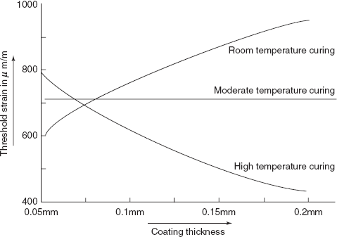
Figure 10.13 Threshold strain vs coating thickness curve
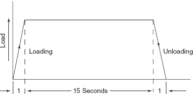
Figure 10.14 Load time history during calibration
10.9 EQUIPMENT FOR BRITTLE COATING METHOD
The equipment necessary for stress analysis through brittle coating is listed below:
- A wide range of brittle coatings.
- An aluminium under coat paint.
- Red dye etchant.
- Etchant emulsifier.
- Two spray guns—one for aluminium under coat and another for coating.
- A small portable air compressor.
- Respirator for operator.
- Focussed light for visual inspection.
- About a dozen calibrating beams.
- A beam bending device.
- A strain scale with beam bending device.
- Temperature and humidity measuring instruments.
- A storage cabinet.
10.10 PREPARATION OF SPECIMEN
The surface of the specimen is lightly rubbed with sand paper, degreased with gasoline, acetone, and finally with carbon disulphide (if coating contains carbon disulphide as solvent) or methylene chloride if the coating contains methylene chloride as solvent. Then aluminium under coat is sprayed over the surface to provide uniform reflecting background, which increases the visibility of cracks. The surface is then ready to be sprayed with the proper grade of brittle coating.
10.11 TESTING PROCEDURE
The specimen with brittle coating is loaded, then load is maintained for 15 seconds on the specimen and then load is released. After unloading the entire surface of the coating is examined for coating cracks. Now the load on the specimen is increased and the entire process is repeated. The crack patterns located after each loading cycle are encircled with line (isoentatic line) and marked with a number corresponding to load on the specimen which produced the strain (see Figure 10.15). Isoentatic line is loci of points of approximately constant principal stress.
If the test is performed on a cylindrical pressure vessel then first family of cracks is perpendicular to σc (hoop stress) and second family of cracks are perpendicular to σa (axial stress).
10.12 CALIBRATION OF BRITTLE COATING
In order to know the stress or strain associated with each isoentatic line it is necessary to calibrate the coating every time when the isoentatic line is plotted. A cantilever beam of rectangular section is fitted in a fixture or beam bending device as shown in Figure 10.16. The cantilever beam has been sprayed with the same grade of coating as on the specimen and has been subjected to the same curing cycle as the coating on the specimen. The beam is deflected through a cam and handles arrangement as shown and it is kept deflected for 15 seconds and then cam is reversed. The cracks on the coating are inspected so as to locate the last crack which separates the cracked and uncracked regions of the coating. The strain corresponding to the last crack on a strain scale of 0 to 2000 microstrain gives the threshold strain ![]() of the coating.
of the coating.
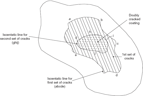
Figure 10.15 Isoentatic lines on coating
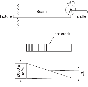
Figure 10.16 Strain scale
Multiple choice QUESTIONS
- Stress coat contains which one of the following base material
- resin
- glass lacquer
- ceramic
- None of there
- What is the range of Poisson’s ratio of stress coat
- 0.42–044
- 044–0.48
- 0.25–0.30
- None of these
- Which one of the following statement is incorrect?
- Brittle coating is a whole field stress analysis technique
- Behaviour of the coating is independent of temperature variation
- Brittle coating technique is of more qualitative nature
- None of the above
- Minimum strain required to crack a particular grades of stress coat is 550 μ strain. If Ec = 1.4 GPa, what is stress in coating.
- 1.1 MPa
- 0.77 MPa
- 0.70 MPa
- None of there
- When coating crazes
- σ1 = σ2
- σ1 > 0, σ2 < 0
- σ1 < 0, σ2 < 0
- None of these
- Which of the following statements is incorrect?
- Stress coat is highly toxic and flammable
- Strain tec is non-flammable
- Glass lacquer is a mixture of lithium hydroxide and boric acid
- All temp coating is very sensitive to minor changes in temperature
Answers
1. (a) |
2. (a) |
3. (b) |
4. (b) |
5. (a) |
6. (d). |
Practice PROBLEMS
10.1 Explain how uniaxial stress system in specimen develops biaxial stresses in coating.
10.2 What are the merits and demerits of brittle coating technique over strain gage technique?
10.3 Derive the expression for failure theory of the case
10.4 Describe how crack patterns are developed in coating where the load on specimen gradually increases.
10.5 Explain what do you understand by coating craze.
10.6 Describe briefly the load relaxation and refrigeration techniques for getting cracks in coating
10.7 Explain the following
- Statiflux method
- Red eye etchant method of crack detection
10.8 Compare the properties of All Temp with the properties of Stress coat.
10.9 Explain the procedure for calibration of brittle coating.