12
Aircraft Structures
12.1 INTRODUCTION
The analysis of stresses in aircraft components is based on different assumptions than the analysis of stresses in beams or columns made of rolled sections. In aircraft construction, thin sheet of an aluminium alloy is riveted to stringers or flanges, and these thin sheet panels or webs are ineffective in sharing the bending loads. These thin webs are supposed to take only shearing stresses. Basically, the shear flow in the thin webs is analysed for a box beam section or an open box beam section. Under design requirements, cutouts are provided in wing structure and fuselage (body) structure. Shear flow in thin open box section redistributes the shear flow in the adjoining closed box section. Majority of the webs in aircraft construction are tapered webs and shear flow in tapered webs changes along the length of the web because area enclosed by thin webs goes on changing along the taper. Then the bulk heads (or rings) in the fuselage structure join the thin sheet with the help of stringers and loads are considered to be applied on bulk heads only. Bulk head distributes the skin into several panels and shear flow in each panel is analysed. In the open box section, to eliminate the development of torsional moment, location of shear centre is determined, so that if load is applied on shear centre, open box section does not distort.
In this chapter we will discuss the construction of wings and fuselage, shear centre, distribution of shear flow in webs and stringer in one plane, shear flow in thin curved webs, shear lag effect, shear load in wing ribs, loads on bulk heads and shear flow in webs, shear flow in tapered webs, effect of cut-out on shear flow on semimonococque structure of wing.
12.2 STRUCTURAL COMPONENTS OF AIRCRAFT
Basic airframe components are: (i) wings or main frame, (ii) body or fuselage, (iii) tail piece, and (iv) undercarriage. In this chapter we will deal only with wings and fuselage.
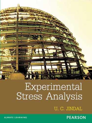
Fuselage acts as beam resisting bending loads imposed by weight of the structure and occupants and air loads. Rings or frames help in maintaining cross-sectional shape and to distribute concentrated loads, to provide edge restraint to skin, and to resist circumferential loads. Stringers (longerons) resist bending and axial loads. They divide the skin into small panels. They act with the skin to resist axial loads caused by pressurization. Figure 12.1 shows the sketch of a fuselage structure showing rings, stringer, and the skin cover.
Wings are designed to generate lift from the air flow over them, which is necessary for the flight of an aircraft. Wings are the main component of an aircraft. These are made strong and stiff to resist the forces of drag and lift. These forces of lift and drag try to bend the wings.
Wings transmit lift to the root through the span-wise beam, inertia loads from power plants and undercarriage etc. to the main beam. Wings provide the aeroelastic stiffness to satisfy the aeroelastic requirements. Components of wings are:
- span wise members called spars, main spanwise beam of a wing,
- ribs, which are chordwise members,
- stringers or spar caps, and
- skin.
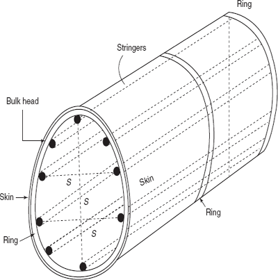
Most important parts of wing structure are spars and stringer as shown in Figure 12.2. In some aircraft there is only one spar.
In monococque construction, skin takes the entire load. Usually very heavy structure or thick sheet is employed to make wings to avoid buckling.
In semimonococque construction, there is thin shell in structure supported by longitudinal stiffeners and spars.
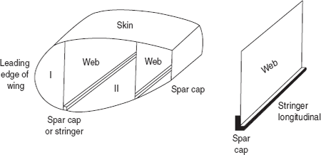
Figure 12.2 Front spar I and rear spar II-wings
Figure 12.3 Internal structure of a wing
Figure 12.3 shows the internal structure of a wing, showing spars and ribs in which ribs maintain aerodynamic shape. They act with skin to rest distributed aerodynamic loads. Ribs increase column buckling strength of stringers through end restraints. They increase skin panel buckling strength. Usually ribs have flanges around edges, so that they can be riveted to the skin and spar webs. Holes are cut through ribs-webs to reduce weight.
Skin is an impermeable aerodynamic surface. Skin transmits aerodynamic forces to ribs and stringers. Skin is riveted to rib flanges and stringers. Countersunk rivets are predominantly used to reduce drag.
12.3 SHEAR CENTRE
A beam of section, symmetrical about x-axis but unsymmetrical about y-axis, is shown in Figure 12.4. If a vertical load is applied along y-axis of the beam and the beam section is unsymmetrical, then the beam is unstable in carrying this vertical load and in addition to bending moment, there will be a twisting moment developed in the beam section, causing distortion in beam. In order to produce no torsion in beam, vertical load is not applied at centroid G of the section but it is applied at the point SC (shear centre). This point, i.e. shear centre, can be obtained by finding the position of the resultant of the shear stresses on any cross-section. Figure 12.4 shows the simplest type of beam (generally present in an aircraft structure of leading edge of a wing) consisting of two concentrated flange areas and a thin web connected at flanges.
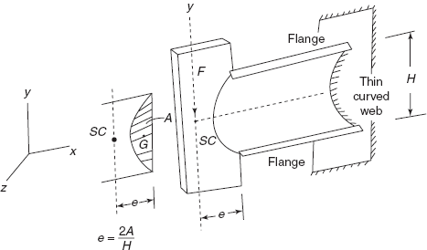
If the web resists no bending, (generally a thin web is ineffective in resisting bending stresses), shear flow in the web will have a constant value of q (shear flow).
Such that q.L (for equilibrium)
Shear flow, ![]()
Position of shear centre, ![]()
All loads must be applied in a vertical plane which is at a distance of e from the edge of web. Beam section is symmetrical about x-axis, therefore, shear centre will lie on x-axis as shown.
If the beam section is not symmetrical about a horizontal axis the vertical position of the shear centre may be calculated by taking moments of the shear forces produced by the horizontal loads.
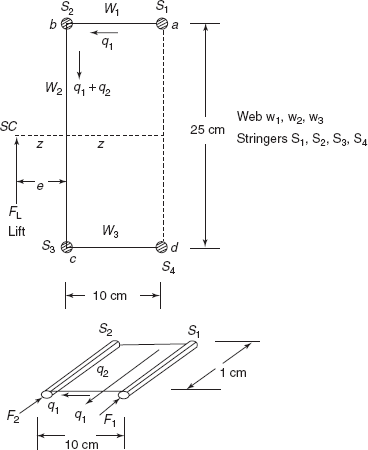
Example 12.1 A beam section consists of four stringers and three webs as shown in Figure 12.5. Area of cross-section of each stringer is 3 cm2 and web thickness is 1 mm. Webs are assumed to carry no bending stresses. Find the shear centre of the section and draw shear stress distribution diagram for a lift of 4.0 kN.
Solution: Moment of inertia about zz-axis,
Izz = 3 × 4 × (12.5)2
= 1875 cm4
Consider 1 cm length of the beam (see Figure 12.5)
Bending moment,
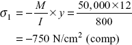
Stress in stringer 1 ![]() stress in S1 and S2 will be compressive
stress in S1 and S2 will be compressive
Force on stringer 1
Force,
F1 = σ1 × area
= −26.667 × 3
= −80 N
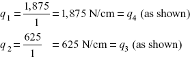
Shear flow, |
|
|
q1 = 80 N/cm as shown |
Stress in stringer 2, |
|
|
σ2 = –26.667 N/cm2 |
Force in stringer 2, |
|
|
F2 = –26.667 × 3 = –80 N |
Shear flow |
q2 = 80 N/cm |
Shear flow in web |
w1, q1 = 80 N/cm |
Shear flow in web |
w2, q1 + q2 = 160 N/cm |
Stringer S4
Stress in stringer 4 (Figure 12.6)
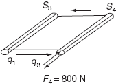
Figure 12.6 Stresses in stringers
Shear force in web
Force in horizontal webs
Taking moments about edge cb
where FL is lift load,
Shear stress in web 1, at a
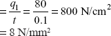
Shear stress in web 1, at b
Shear stress in web 2, at b and c
Shear stress in web 3, at c = 16 N/mm2
Shear stress in web 3, at d = 8 N/mm2.
Figure 12.7 shows the shear stress distribution in channel section made of four stringers and three webs.
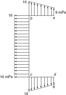
Figure 12.7 Shear stress distribution, stringers and webs in channel section
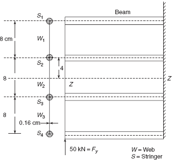
Example 12.2 Figure 12.8 shows a beam and cross-section of a beam, having four stringers of area of cross-section 2.5 cm2 each and webs of thickness 0.16 cm each. Assume that webs are ineffective in resisting normal stress but capable of transmitting shear stress. Each stringer is assumed to be lumped at a point. Find the shear stress distribution in web. Force at free end is equal to 50kN.
Solution: Consider a section X-X at a distance of 1 cm from free end.
Bending moment,
Moment of inertia of beam section about zz-axis (neglecting the area of webs)
Normal stress in stringer S1,
Normal stress in stringer S4,
Normal stress in stringer S2,
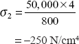
Normal stress in stringer S3,
Normal stress in stringer S1,
Stringer S4,
Shear flows
Shear flow between d and c (web 3) = 1,875 N/cm
Shear stress in web 3

Shear flow between c and b (web 2)
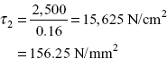
Shear stress in web 2
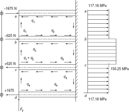
Figure 12.9 Shear stress distribution in webs
Shear flow in web 1 (between b and a) = 1,875 N/cm
Shear stress in web 1,
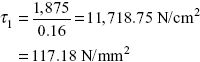
Figure 12.9 shows shear stress distribution in webs, i.e. in web 1 and web 3 τ1 = τ3 = 117.18 MPa and in web 2, τ2 = 156.25 MPa.
Exercise 12.1 An aircraft structure makes a channel section with four stringers and three webs as shown in Figure 12.10. Area of cross-section of rear stringers in 3.2 cm2 and area of cross-section of front stringers is 6.4 cm2 each. Web thickness of top and bottom webs is 1.0 mm and web thickness of vertical web is 1.2 mm (assume that webs do not take any bending stress). Determine shear centre location. Draw shear stress distribution in web, if vertical lift is 18 kN.
Ans. [e = 2.667 cm, τa = 25 MPa, τb = τc = 75 MPa, τd = 25 MPa].
Exercise 12.2 Figure 12.11 shows a part of a wing structure subjected to vertical lift F. Each stringer has an area of cross-section of 3.6 cm2. Thickness of web is 1.2 mm. What is the maximum value of F so that shear stress in webs does not exceed 50 MPa? Assume that webs do not take any nor mal stress.
Ans. [144 kN].
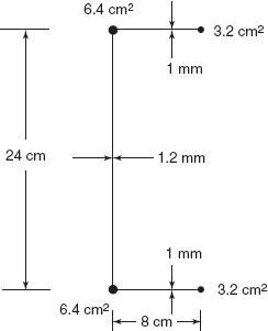
Figure 12.10 Exercise 12.1
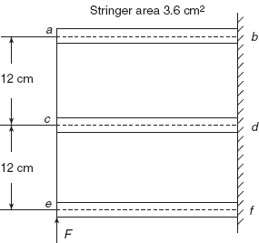
Figure 12.11 Exercise 12.2
12.4 SHEAR FLOW IN THIN WEBS
The cover of an aircraft is made from a thin sheet of an aluminium alloy. Leading edge of a wing represents a closed box section made of thin web as shown in Figure 12.12. The wing is subjected to a vertical lift, producing shear flow q in web as shown. Due to the air loads normal to the surface of thin curved web, shear stresses perpendicular to the surface are negligible. If the shear flow q is known, then shear stress in web is ![]() where t is the thickness of the web. The thickness of the web can be uniform throughout or it can vary.
where t is the thickness of the web. The thickness of the web can be uniform throughout or it can vary.
Considering an element on the surface of thin curved web or straight web, shear stresses t on an element are shown in Figure 12.13. Due to these shear stresses, principal stresses developed on the surface of web are
pt = +τ, tensile principal stress
pc = −τ, compressive principal stresss at angles of ± 45° with the direction of τ.
The diagonal compressive stress, pc = −τ, causes wrinkles on the surface of the web if pc exceeds the minimum compressive stress required to cause wrinkles on the web.
A leading edge of wing is subjected to torsional moment T about its geometrical axis zz passing (Figure 12.14) through the centroid G of the section. As per the breadth Botha equation given in Chapter 5.
Shear flow, ![]()
where A = area enclosed by the centre line of the section.
Shear stress, τ, at any place is given by, ![]() , where t is the thickness. Maximum shear stress will occur in section where thickness is minimum (Figure 12.14).
, where t is the thickness. Maximum shear stress will occur in section where thickness is minimum (Figure 12.14).
Leading edge of wing subjected to vertical lift: Leading edge of the wing is subjected to vertical lift force Fl. Then for equilibrium shear flow in vertical web ac will be
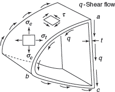
Figure 12.12 Curved web-Leading edge of wing
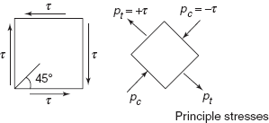
Figure 12.13 Shear stresses on an element
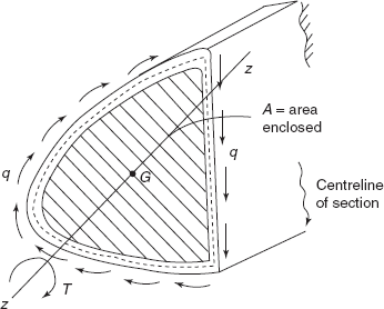
Figure 12.14 Leading edge wing
Shear flow in curved web ![]() will be equal to q as shown in Figure 12.15. Taking moments of the forces about the edge c of the webs. (Shear flow integrated over the curved surface)
will be equal to q as shown in Figure 12.15. Taking moments of the forces about the edge c of the webs. (Shear flow integrated over the curved surface)
or distance, ![]()
but Fl = qH
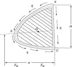
Figure 12.15 Lift force
Therefore, distance, ![]() , for no torsional moment on web.
, for no torsional moment on web.
Example 12.3 Leading edge of an aircraft is approximated as a section semicircular and rectangular as shown in Figure 12.16. Height H = 20 cm. Radius of semicircle is 10 cm. Thickness of straight vertical web, ea is 2 mm. Thickness of web abcde is 1 mm only. A vertical lift on 20 kN is applied at O. Determine shear stresses in vertical web ea and semicircular web bcd.
Solution: Distance H = 20 cm
Say q is the shear flow
Shear stress in vertical web,
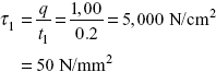
Shear stress in curved web,
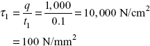
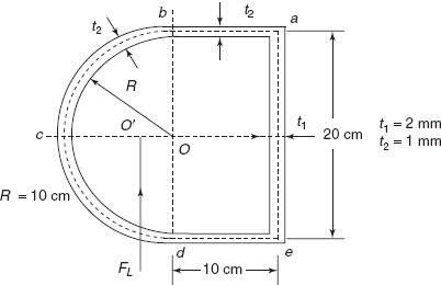
Figure 12.16 Leading edge of aircraft
Example 12.4 A box section structure of an aircraft made of thin aluminium alloy sheet supported by stringers is shown in Figure 12.17. Shear flows in webs are also shown. If G = 30 kN/mm2 for alloy, determine angular twist over a length of 2.5 m of structure.
Solution: Let us determine ![]() from below table.
from below table.
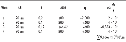
Area,
Angular twist,
(refer to chapter 5)
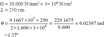
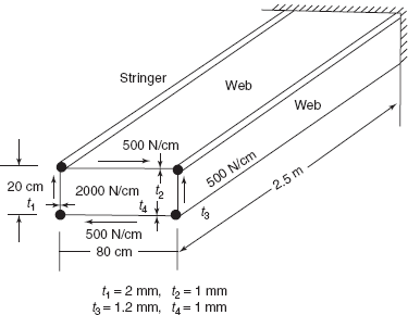
Figure 12.17 Box section of aircraft
Exercise 12.3 A structural part of an aeroplane has a section shown in Figure 12.18, made of thin sheet of aluminium alloy. A torque of 8 kNm is applied about its geometrical axis. Determine sheer flow in section. Determine angular twist in this part per metre length, if G = 24 kN/mm2.
Ans. [q = 418 N/cm, stresses 20.9, 27.87, 40.18 N/mm2, θ = 0.5°].
Exercise 12.4 A box section structure of an aircraft made of stringers and webs of thin aluminium alloy is shown in Figure 12.19. Shear flows in webs is shown along with thickness of web. Determine angular twist over a length of 3 m, G = 28 kN/mm2.
Ans. [1.3°].
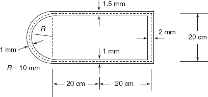
Figure 12.18 Structural part of an aeroplane
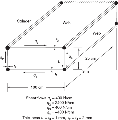
Figure 12.19 Shear flows in webs and stringers
12.5 SHEAR LAG
Aircraft structure is made by riveting thin skin (aluminium alloy) to the strong solid stringers as shown in Figure 12.20. Stringers are capable of resisting bending stresses produced due to bending moment caused by FL, lift load. Figure 12.20 shows a cantilever beam fixed at one end and free at the other end. Thin web (thin sheet) is connected to stringers abcde at top and f, g, h, I, and j at bottom. Say the load FL is applied through central stringers c and h as shown, causing bending moment in cantilever, FL × L at the fixed end. Bending moment changes linearly along the length of the beam. Due to bending moment upper stringers come under compression, and lower stringers come under tension. The assumption that plane section remains plane after bending moment is applied is not applicable in this structure because thin web is ineffective in taking up the bending loads and thin web can only resist shear stresses. Figure 12.20 shows a beam of solid cross-section subjected to bending moment, in this case plane section abcd has just rotated about neutral layer and takes up new position a′b′c′d ′. But this assumption in aircraft structure had failed during heavy shear deformations of webs and redistribution of bending loads in stringers. At the ends there is no deformation because end is fixed. But considering a section away from the fixed end, as section abcdejihgf. Upper stringer deform as shown, with maximum deformation (compression) in central stringer c, while lower stringers deform with maximum deformation (tension) at central stringer h. As a result the section is heavily distorted.
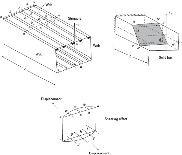
Figure 12.20 Skin riveted to stringers
Redistribution of bending loads or bending stresses in box beam is commonly known as shear lag. In the section shown, section is symmetrical about central line hc, bending plane is plane of symmetry; there will not be any torsional deformation.
Stringer which are under compression tend to fail as column, with length equal to rib spacing, spar caps are supported vertically by the spar web and horizontally by the skin, and they usually resist high compressive stresses.
Multispar wings are better for providing skin bucking stability. There is a low aspect ratio with closed packed matrix of ribs and spars in wings.
Effect of shear lag is desirable, since it permits a structure to resist higher ultimate bending moments, than those calculated from the simple flexure theory.
If a cantilever of thin I-section is subjected to a vertical load, FL at its free end as shown in Figure 12.21, top flange will distort inwards and bottom flange will distort outwards as shown. This effect is known as shear lag effect.
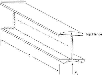
Figure 12.21 Shear lag effect on thin I section
12.6 SHEAR LOAD ON WING RIBS
Beam shown in Figure 12.22 is similar to a wing rib which is supported by spars at ends and which resists the load of 12 kN as shown. The stiffener ab transmits this load of 12 kN to the two webs in inverse proportion to lengths 25 and 50 cm as shown, i.e. 4 kN load on left side web and 8 kN load on right side web. A force opposite to 4 kN force, per unit length, gives q1, shear flow = ![]() . Similarly shear flow
. Similarly shear flow ![]() = 320 N/cmas shown.
= 320 N/cmas shown.
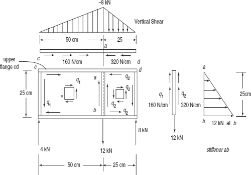
Axial load in ab = 12 kN at b decreasing to 0 at a.
Axial load in the upper flange, cd = 50 × 160 = 8,000 N
(0 at c increasing to 8 kN at a)
= 25 × 320 = 8,000 N
= 8 kN
(0 at d increasing to 8 kN at a) as shown by vertical shear.
Exercise 12.5 Figure 12.23 shows a wing rib 84 cm long and 24 cm high, supported by spars ce and df at the ends. Wing rib resists a load of 14 kN as shown. The stiffener ab transmits the loads to the two webs cabd and abfe. What is the shear flow in webs? What is the vertical shear load on upper flange ce? Show the shear flow in webs, vertical shear in upper flange, and axial force variation in stiffener ab.
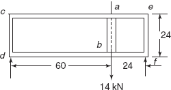
Figure 12.23 Exercise 12.5
Ans. [q1 = 166.67 N/cm, q2 = 416.67 N/cm; Vertical shear 10 kN at c, zero at c and zero at d increasing to 10 kN at a, kN varies 0 to a to 14 kN at b].
12.7 LOADS ON BULK HEADS
Bulk heads are attached to the skin of fuselage or skin of wing continuously around their perimeter. Bulk head unit transfers the concentrated loads to the shell fuselage (e.g., skin of fuselage) or to the skin of the wing. Bulk heads of fuselage are open frames or rings so that interior of the fuselage is not obstructed. In wings, chordwise bulk heads are called ribs. Moreover, bulk heads provide column support to the stringers (longerons) and redistributes shear flow in the skin.
Loads on bulk heads are considered in static equilibrium. Fuselage shells are generally symmetrical about a vertical centre line and often loaded symmetrically with respect to the vertical centre line.
Bending stress in any flange (or stringer), ![]() where M is the bending moment.
where M is the bending moment.
Shear flow, ![]()
where Vb is vertical load on bulk head.
Shear flow is zero at top and bottom of centre line. If the stringers or longerons are located at the bottom or top of the centre line, half of their area is considered to act with each side of the structure of bulk head (Figure 12.24).
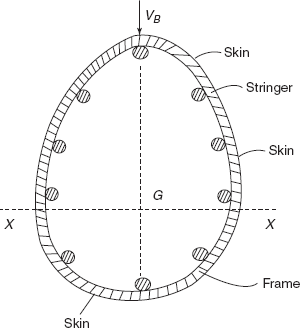
Figure 12.24 Bulk head fuselage
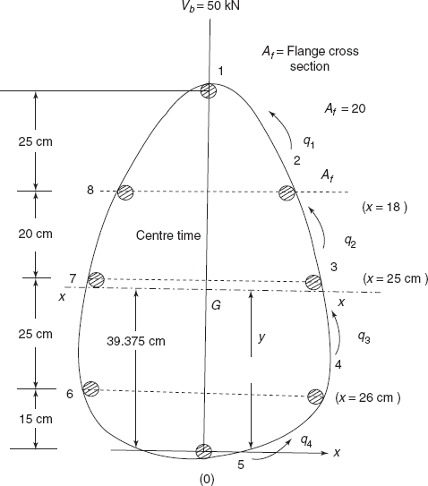
Example 12.5 A fuselage bulk head is shown in Figure 12.25. Vertical load on bulk head is 50 kN. There are eight stringers with area of cross-section of 2 cm2 each. Show the shear flow in webs. If the thickness of the skin is 2 mm, what is the maximum shear stress in skin?
Solution: Consider only one half of the bulk head and one half on load also.
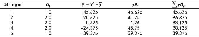
Let us first determine the position of centroid (considering only the stringers) and moment of inertia Ixx.
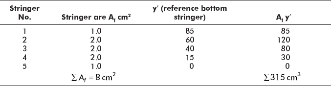
Axis x–x is located at 39.375 cm from bottom stringer.
Moment of inertia,
Ixx = 1 × (85 − 39.375)2 + 2(60 − 39.375)2 + 2(40 − 39.375)2 + 2(39.375 − 15)2 + 1(39.375)2
= 1 × 2,081.64 + 2 × 425.39 + 2 × 0.39 + 2 × 594.14 + 1,550.39
= 2,081.64 + 850.78 + 0.78 + 0.75 + 1,188.28 + 1,550.39
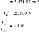
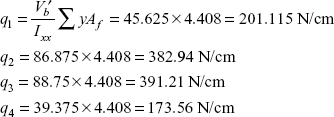
Maximum shear flow = 391.21 N/cm
Skin thickness = 2 mm = 0.2 cm
Maximum shear stress ![]()
= 1,956 N/cm2
= 19.56 N/mm2
Figure 12.26 shows the shear flow distribution on the webs ofbulk head. Diagram can be repeated for the left side also.
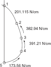
Figure 12.26 Shear flow diagram on webs of bulk head
Exercise 12.6 A fuselage bulk head is approximated as a ring of diameter 1 m consisting of eight stringers of area of cross-section 2 cm2 as shown in figure 12.27. Point load on buck head is 60 kN. Determine shear flows in web, if skin thickness is 1.5 mm, what is maximum shear stress in skin?
Ans. [q1 = q4 = 150 N/cm, q2 = q3 = 362.1 N/cm, τmax = 24.14 MPa].
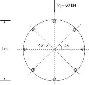
Figure 12.27 Exercise 12.6
12.8 SPANWISE TAPER EFFECT ON SHEAR FLOW IN WEBS
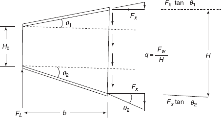
Beam consists of a two stringers inclined at angles θ1 and θ2 with the horizontal and joined by a single vertical web. The web is not effective in resisting bending. Web can only resist shear stresses (Figure 12.28). Vertical load at free end = FL.
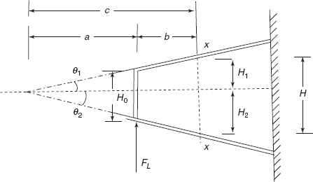
Bending moment a distance b, Mx = FLb
Horizontal component of force in stringer (compressive force in upper stringer and tensile force in lower stringer)
(![]() and
and ![]() constitute a couple of moment Fx H).
constitute a couple of moment Fx H).
Vertical components of Fx
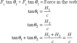
Ff, force in flange = ![]()
Force on web = FL – Ff
Fw = Force in web = ![]() , shear flow in web =
, shear flow in web = ![]()
But FL = q0H0
So q, ![]()
12.9 SHEAR FLOW IN TAPERED WEBS
Majority of webs used in aircraft structure are tapered as shown in Figure 12.30. All four webs are tapered in the same ratio, so that shear flow obtained will be the same for all four webs at a particular section.
Shear flow when x = x0
Shear flow at any section at a distance of x from apex o is

At a distance x, when (x − x0) = b, moment of the force FL, M = FLb but FL = q0 H0
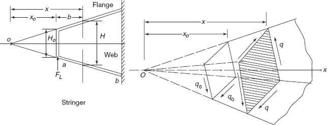
Figure 12.30 All the four sides of section are equal
Horizontal component of flange load, P
Average shear flow, qav (over a distance b)
Figure 12.31 shows the shear flow variation along the axial length of the tapered web (equally tapered on all four sides).
If the tapered webs are only two vertical sides and other two sides of the box section (Figure 12.32) are rectangular webs of constant breadth a, then on vertical webs, shear flow
On rectangular webs of constant breadth,
Difference between shear flows on vertical webs and adjacent slanting rectangular webs produces axial loads in the flange member between these webs.
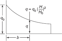
Figure 12.31 Shear flow variation
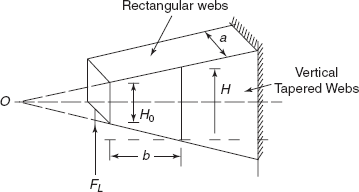
Figure 12.32 Box section
Example 12.6 A tapered box section, having all four webs tapered from 20 cm side to 30 cm side over a length of 1 m, is subjected to a lift load of 10 kN at the free end. Box section is held as a cantilever. Determine shear flow at free end, fixed end, and at centre of beam. What is the average shear flow in web?
Solution: Figure 12.33 shows a cantilever beam with sides
H0 |
= |
20 cm |
H1 |
= |
30 cm |
H′ |
= |
25 cm (in the middle) |
FL |
= |
Lift load = 10 kN = 10,000 N |
|
|
Shear flow at free end = |
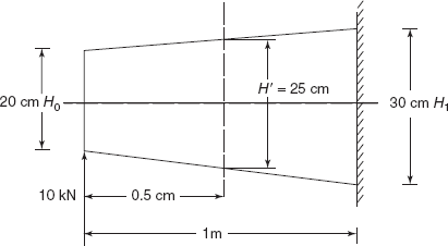
Figure 12.33 Cantilever beam
q′ = Shear flow at centre =
q1 = Shear flow at fixed end =
Average shear flow,
Average shear flow,
Exercise 12.7 A closed box section is made by four stringers, and two vertical webs which are tapered from 20 cm to 25 cm over a length of 80 cm and two slanting webs of uniform width of 20 cm, as shown in Figure 12.34. (a) A vertical lift load of 4.0 kN acts at the free end. What are shear flows in tapered webs at free and fixed ends and what is shear flow in rectangular webs? (b) An axial torque of 1.2 kNm acts on the beam, what are shear flows at free end and fixed end?
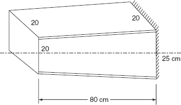
Figure 12.34 Exercise 12.7
Ans. [(a) 200 N/cm, 128 N/cm, 160 N/cm; (b) 150 N/cm, 96 N/cm].
12.10 CUTOUTS IN SEMIMONOCOCQUE STRUCTURES
Though the majority of beams in aircraft structure are of closed box section type with longitudinal stiffeners (stringers) and transverse bulk heads (frames or rings), yet there are necessary openings in aircraft structure to provide wheel wells, space for retraction of landing gear, opening for armament installations, space for fuel tanks, etc. Fuselage constructions provide doors, windows, cockpit openings, etc. Moreover, it is also necessary to provide holes and doors for access during manufacture and inspection of aircraft structure. But, these cutouts are undesirable from the point of view of structural stability but are necessary regions where high loads must be resisted and frequent reinforcement around cutout is provided.
A beam with a large cutout B × H is shown in Figure 12.35. Beam is fixed at one end and a twisting moment T is applied on the beam at the free end. Twisting moment T is applicable as a couple of forces ![]() with an arm length B.
with an arm length B.
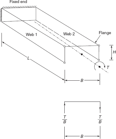
Figure 12.35 Cut out in structure
Since the beam is fixed at one end, twisting moment T is resisted by two side webs of length L and depth H as shown.
Vertical force in web 1, = ![]() upwards shear flow in web 1,
upwards shear flow in web 1,
(Shear flow in web of an open section B × H)
Horizontal force in upper flange, F1 = q1L
(resisting the shear flow) = ![]()
So, the axial force in upper flange is compressive for F1. Axial force in lower flange will be tensile force F′1, as shown Figure 12.36 ![]() .
.
The horizontal web resists no shear, in case of pure torsion loading. Shear flow on the right-hand side web 2 and axial forces in flanges are shown in Figure 12.37.
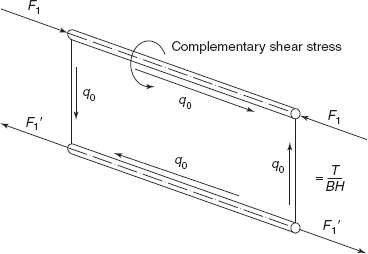
Figure 12.36 Axial force in flanges
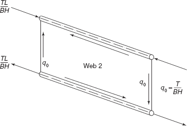
Figure 12.37 Shear flow in web 2
The shear deformations of the webs are negligible in comparison with bending deformation of the cantilever beam, i.e. flanges.
In a full cantilever aeroplane wing, it is not feasible to have an open ended structure throughout the span because for some flight conditions, the wing tip would twist to an excessive angle. A closed torque box is necessary for most of the span and where necessary for a short length a cutout can be provided. For a closed box section of the same dimensions, subjected to same twisting moment, shear flow will be reduced to half, as shown in Figure 12.38.
Shear flow in closed box section,
where q0 shear flow in open section.
Figure 12.39 shows shear flows in closed and open boxes.
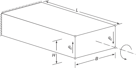
Figure 12.38 Shear flow in closed box
Figure 12.39 shear flows in closed and open boxes
A cut out in a short length of wing structure affects the shear flows in the adjacent sections of the wing which have closed torque boxes. On vertical rib, shear flow 1.5qc as shown in Figure 12.40.
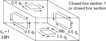
Figure 12.40 On vertical webs shear flow 0.5 qc (qc − 1.5 qc = 2qc − 1.5 qc = 0.5 qc) on horizontal webs shear flow 1.5qc
Open section: Vertical webs, shear flow ![]()
Rib: q0 – 0.5qc = 2qc – 0.5qc = 1.5qc, shear flow in rib.
The effect of cut out is that shear flow in webs of closed box is redistributed to 1.5qc on top and bottom webs (increase by 0.5qc) and on side vertical webs, shear flow is 0.5qc (decrease by 0.5qc) (Figure 12.40).
Example 12.7 An open box section is subjected to a vertical lift on 40 kN, a horizontal force 10 kN at O and a clockwise twisting moment 4 kNm as shown in Figure 12.41. Determine shear flow in three webs of open box section. What are the forces in four flanges a, b, c, and d?
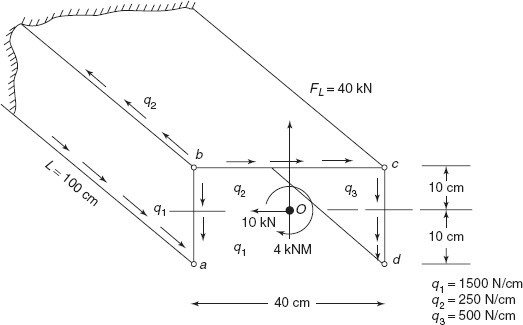
Figure 12.41 Open box section
Solution: Taking moments about point C
20q1 × 40 = 40,000 × 20 + 4 × 10⁵ Ncm
800q1 = 8 × 10⁵ + 4 × 10⁵
q1 = 1500 N/cm ↓ (as shown) (downward)
For equilibrium
20 × q1 + 20q3 = 40,000
20 × 1,500 + 20q3 = 40,000
20q3 = 40,000 − 30,000 = 10,000
q3 = 500 N/cm ↓ (downward)
Force in flange a,
Pa = q1 × length
= 1,500 × 100 N
= 150 kN (tensile) (Resisting force in web)
Force in flange d,
Pd = q2 × length
= 500 × 100 N
= 50 kN (tensile) (Resisting force in web)
Equilibrium of horizontal forces
40q2 = 10,000 N
q2 = 250 N/cm
Total of forces
Force in flange b,
Pb = (q1 + q2) × 100
= (1,500 + 250) × 100
= 175 kN (comp.)
Force in flange c,
Pc = (500 − 250) × 100
= 25 kN (comp.)
Pb + Pc = 175 + 25 = 200 kN = Pa + Pb
These forces satisfy the condition of static equilibrium. For an open section beam containing four flange members, the flange loads are independent of the flange areas.
Figure 12.42 shows the shear flow in webs and axial forces in flanges. Figure 12.43 shows open box between two closed boxes. Figure 12.44 shows shear flow in webs.
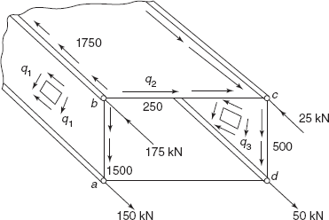
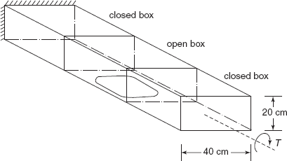
Figure 12.43 Closed and open boxes
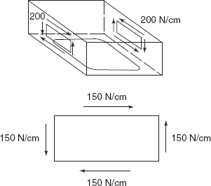
Figure 12.44 Shear flow in webs
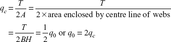
Example 12.8 A cantilever of length 3L, fixed at one end, free at the other end is subjected to a twisting moment of 1.6 kNm, breadth of cantilever is 40 cm and depth is 20 cm. Draw the shear flow distribution in closed box section, open box section (with a cutout and in the rib).
Solution: |
T = 1.6 × 10⁵ Ncm |
|
A = area = B × H |
|
= 40 × 20 = 800 cm2 |
qc = shear flow in closed box section
q0 = 2qc, shear flow in open box section
In the open box section, no shear flow on top horizontal web. On vertical webs, shear flow is q0 = 200 N/cm as shown.
Rib:
Closed box section:
On vertical web,
On horizontal web,
Shear flow on top and bottom webs is 150 N/cm and shear flow on vertical webs is 50 N/cm as shown in Figure 12.45. For closed box section shear flow is redistributed due to the cut out in the central portion.
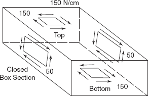
Figure 12.45 Shear flow on top and bottom webs
- Sometimes wrinkles are formed on webs. The reason of wrinkle formation is
- buckling of thin sheet of web
- tensile principal stress
- compressive principal stress
- None of these
- If bending load is applied at shear centre of the section of the beam then
- bending stress in beam will be zero
- no torsional moment will occur on beam section
- no buckling of the beam
- None of these
- A beam consists of two stringers and a thin vertical web of thickness 1 mm. If the shear flow in web due to the application of bending load on beam is 100 N/cm, what is the shear stress in web section?
- 100 N/mm2
- 50 N/mm2
- 10 N/mm2
- None of these
- What is the effect of shear lag on bending loads of stringers?
- Bending loads do not depend on shear lag
- Bending loads in stringers are redistributed due to shear lag
- Flexure formula can be applied to find bending stresses
- None of these
- A beam is made of square box section tapering from a side of 20 cm at free end to 30 cm at fixed end, section remains square throughout. A vertical load of 10 kN is supplied at free end of cantilever. What is the average shear flow in tapered web?
- 500 N/cm
- 33.3 N/cm
- 222.2 N/cm
- None of these
- A box section 20 × 30 cm is 3 m long. A cut out is provided in the central middle part of 1 m length. A torque of 1.2 kNm is applied on box section. What is the shear flow in cut out portion of the beam?
- 100 N/cm
- 150 N/cm
- 200 N/cm
- None of these.
Answers
| 1. (a) | 2. (b) | 3. (c) | 4. (b) | 5. (b) |
| 6. (c). |
12.1 In the beam cross-section shown in Figure 12.46, the webs are considered as ineffective in resisting normal stress but capable of transmitting shear stress. Each stringer area of 3 cm2 is assumed to be lumped at a point. Find stresses in three webs if a vertical lift load of 40 kN acts at free end.
Ans. [120, 160, 120 MPa].
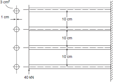
Figure 12.46 Exercise 12.1
12.2 The beam section shown in Figure 12.47 has front spar flange areas which are three times the rear spar flange areas. Length of beam is 3 m. Section is 1 m × 0.25 m. Webs are of thin sheet of aluminium alloy with G = 28 kN/mm2. Thickness of all the webs is 1 mm. Determine angle of twist at free end.
Ans. [2°].
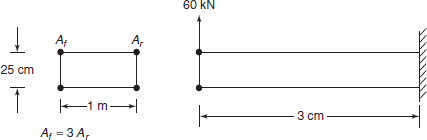
Figure 12.47 Exercise 12.2
12.3 A fuselage bulk head shown in Figure 12.48 is 1 m high, it consists of 10 stringers of area of cross-section 2.2 cm2. Location of stringers is also shown; it is symmetrical about the vertical centre line. If in the vertical load, a point load is 40 kN along the centre line, determine shear flow along the web. If the thickness of skin sheet is 1.6 mm, what is the maximum shear stress developed in skin (Figure 12.48)?
Ans. [ӯ = 49 cm, Ixx = 10140 cm4, shear flow 110.63 N/cm2, 245.12 N/cm, 314.534 N/cm, 258.8 N/cm, 106.3 N/cm, τmax = 19.66 N/mm2].
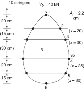
Figure 12.48 Exercise 12.3
12.4 The tapered beam for example (see Figure 12.49) is subjected to an axial twisting moment of 1 kNm. What is the magnitude of shear flow at free end and at fixed end?
Ans. [125 N/cm, 55.55 N/cm].
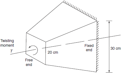
Figure 12.49 Exercise 12.4
12.5 A cantilever beam section 300 cm long, 30 cm wide, and 20 cm deep contains a cut out in the central 100 cm length. The beam section is subjected to an axial twisting moment of 9.6 × 10⁴ Ncm. Determined shear flow in open box section and rib of the cantilever beam (Figure 12.50).
Ans. [qc = 80 N/cm, q0 = 160 N/cm]
Open section: Shear flow = 160 N/cm
Closed section: Top and bottom webs, q = 120 N/cm
Vertical webs, q = 40 N/cm
Ribs: Shear flow = 120 N/cm.
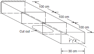
Figure 12.50 Exercise 12.5