
10
Ecodesign of equipment for electricity distribution networks
Abstract
European directives and regulations (Restriction of Hazardous Substances in Electrical and Electronic Equipment (RoHS), Energy-Related Products (ERP), Waste Electrical and Electronic Equipment (WEEE) and Registration, Evaluation and Authorization of Chemicals (REACh)) and International Electrotechnical Commission (IEC) standards in the field of environment are the new driving forces of technological developments for proactive companies. Looking at environmental concerns in the field of electrical distribution network equipment means being interested in the efficiency of the network and medium voltage equipment features. This chapter gives facts on the European and French electrical networks. It describes the state of the art of legislation and standards in the environmental field. An example of the environmental declaration of medium-voltage switchgear according to product environmental profile ecopassport rules is given. It is a fair environmental identity card and a good answer to the market need for ecodesign.
Keywords
Ecodesign; Efficiency; Electricity distribution network; End of life; Medium voltage distribution devices; Medium-voltage network; PEP; Switchgear10.1. Introduction
Electricity is not a source of energy; it is a method of transporting energy from where it is generated to where it is used. World electricity is produced from renewable sources (hydro, combustible renewables and wastes) and nonrenewable sources: nuclear, gas, oil and coal. It has been speculated that the cost of nonrenewable raw materials is about US$3 trillion, that is, 5% of the world's annual gross domestic product (Multon et al., 2012). There is also a cost for the technical and operational losses related to electricity transmission and distribution. These losses are more difficult to measure than one might expect.
Approximately 39% of the total primary energy (i.e. 55,000 TWh or 1.98·1014 MJ) were extracted to give 20,200 TWh of electricity (TWhe); 20,200 TWhe/55,000 TWh yields about 37%, which was marketed as 16,800 Twhe (International Energy Agency (IEA), 2010). The total yield of both primary and final energy is therefore about 30%. Industrial flow of electricity in the world according to the IEA is summarized as follows:
It means that 17% of the electricity produced is not sold; 70% of the energy is lost from the primary energy. Electricity owns a strong potential for contributing to sustainable development: the conversion of total primary energy (142,000 TWh) and total final energy (98,000 TWh) is achieved with a loss of only 31% instead of 63% (100% − 37%).
The use of electricity is increasing (∼2%/year). For example, between 2008 and 2011, global consumption increased by 8%, from 20,169 to 22,017 TWhe (energies, 2013). The share of renewable energy was 3800 TWhe (19%) in 2008, and it increased to 20% in 2011(4447.5 TWhe). This increase occurred at the expense of nuclear power and thanks mainly to a doubling of the share of wind power (energies, 2013).
In France, the historical operator of electricity (Électricité de France) supplies about 90% of the electricity consumed in France. It owns about 85% of the installed capacity. The Électricité de France owns two sister companies: Réseau de Transport d’Électricité (RTE), which routes electricity over long distances, and Électricité Réseau Distribution France (ERDF; http://www.erdfdistribution.fr/), which distributes electricity to customers. In 2012, French consumption was 489.5 TWh for a production of 541.4 TWh (RTE, 2013).
Figure 10.1 depicts the electrical network in France. Dams and nuclear power and carbon plants generate electricity. At first it is sent through a step-up transformer, which increases the voltage level and sends the electricity to transmission lines. Electricity then is conveyed over long distances in high-voltage lines called HTB (400, 225, 90 and 63 kV) and managed by RTE. It may be then converted into the medium-voltage network called HTA (from 1 to 50 kV, usually 20 kV) to be routed by the distribution network, which is managed at 94% by ERDF. Transformation from HTB to HTA takes place in 2240 transmission substations, which contain transformers that lower the voltage of electricity before it is distributed. The electricity then feeds directly to 107,900 industrial customers (HTA) or 35 million other customers. In the latter case, the electricity is converted to low voltage (BT) in 750,400 HTA/BT distribution substations before being delivered. In the end, the quality of the supplied electricity is the result of the quality of the whole course:
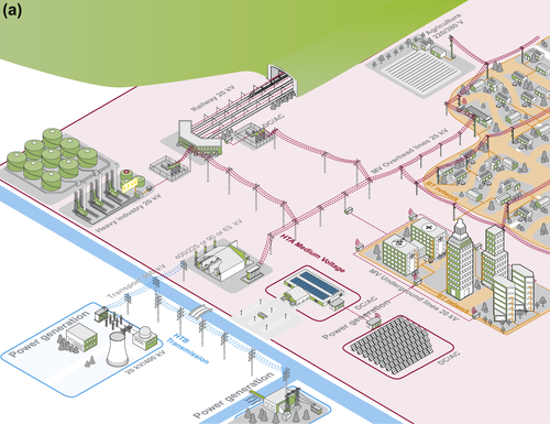
• about 100,000 km of HTB lines,
• 613,200 km of HTA lines (43% underground network),
• 692,000 km of BT lines (40% underground network).
In 2012, losses – calculated as the difference between the French electricity produced and the electricity marketed – were only about 10%. The losses from the French network are from both the RTE and ERDF networks. About one-third of electrical loss on the HTA and BT networks comes from nontechnical problems such as fraud and disputes, which comprise 2.5% and 3.5%, respectively, of the total amount of electricity injected (Les dispositifs, 2014). The 6% of the network that is not managed by the ERDF undergoes a loss of about 1 TWh (Les dispositifs, 2014). Assuming 0.0575 €/kWh, this gives ∼€3 billion in losses per year. The networks themselves are the most important consumer of electricity in France.
Because of the liberalization of the European electricity market, the development of renewable energy, investments in maintaining the nuclear power stations, carbon dioxide quotas and other European regulations for companies in the manufacturing industry, the average price per megawatt hour increased by 70% in a single year: from €39.6 in 2010 to €57.5 in 2011 (DGCIS, 2013). Furthermore, in deregulating the electricity market, the European commission has created stock exchanges, auction markets and securitization through call options. The buyer of the call option buys a right (the fee paid is called a premium) to buy an agreed quantity of electricity at a certain time (the expiration date) for a certain price (the strike price). Such marketing has made the management of the electrical network drastically complex.
10.2. Legislation and standards in Europe relating to energy-efficient design
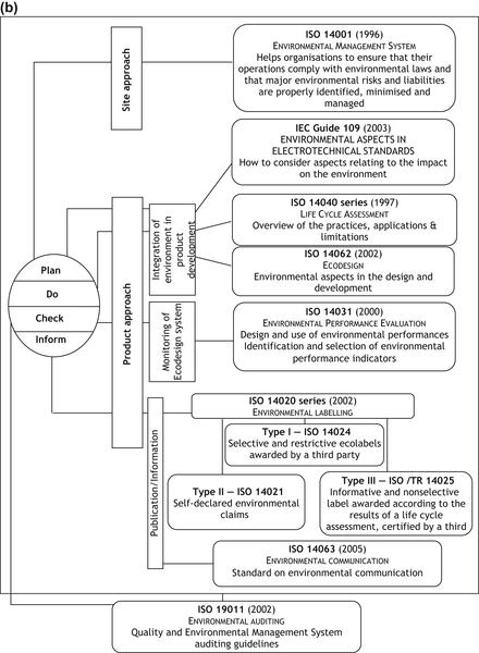
The International Standard Organization (ISO) together with the International Electrotechnical Commission (IEC) have built a strategic partnership with the common goal of promoting standards specific to environmental management (Figure 10.2(a)). (The ISO 14,000 series helps organizations both to manage better the impact of their activities on the environment and to demonstrate sound environmental management (Figure 10.2(b)).)
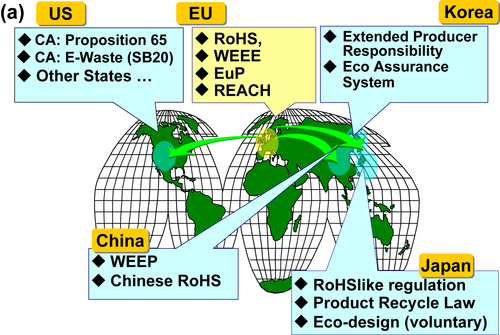
Beyond these international organizations, the European community, through its commission, is presently a pioneer in the promotion of ecodesign and cleaner production. European legislation in the environmental field represents a reference for worldwide legislation.
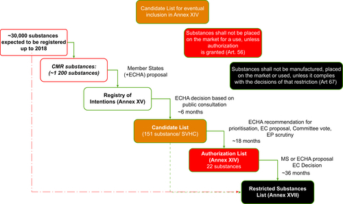
The Registration, Evaluation and Authorization of Chemicals regulation (REACh) (http://europa.eu/index_fr.htm (January 2010)) establishes a single integrated system of registration, evaluation and authorization of chemicals marketed in the European Union (Figure 10.3). REACh requires a registration process and environmental and toxicological evaluation (1907/2006/EC) from all producers and/or importers of substances or preparations put on the European market. In addition, it sets up the principle of traceability of substances of very high concern (SVHCs) when used in articles. A substance may be listed as an SVHC if it meets one or more of the following criteria: carcinogenic; mutagenic; repro-toxic; persistent, bioaccumulative, toxic for the environment or very persistent, very bioaccumulative. All European companies (manufacturers, importers, distributors and/or downstream users) may be concerned by REACh. Manufacturers or importers of articles containing more than 0.1% (by weight) of any SVHC must, upon request, provide their customers and consumers with adequate information on the safe use and disposal of the article, including the name of the SVHC(s) concerned (Hassanzadeh, Theoleyre, & Metz, 2011).
To support sustainable design, the European Community environmental legislation continuously develops new legislation relating to the energy efficiency of industrial products. Several main European directives are of interest to low-voltage electrical and electronic equipment and soon should affect electricity distribution network equipment. The energy efficiency of products is enshrined in a broader integrated approach.
• The manufacturing phase is addressed by the Restriction of Hazardous Substances in Electrical and Electronic Equipment (RoHS) directive (2002/95/EC). The RoHS directive aims to protect human health and the environment through the restricted use of certain hazardous substances. From 1 July 2006, amounts of lead, mercury, chromium, cadmium, hexavalent chromium and two flame retardants – polybrominated biphenyls and polybrominated diphenyl ethers – have been restricted to less than 0.1% (1000 ppm) in new electrical and electronic equipment (cadmium content is bounded below 0.01% (100 ppm)).
• The use phase is addressed by the Energy-related Products (ErP) directive (2009/125/EC; formerly Energy-using Products (2005/32/EC)). It aims to create a comprehensive and coherent legislative framework for addressing ecodesign requirements. This directive is associated with the Energy Labelling directive. The ErP directive addresses the supply side, whereas the Energy Labelling directive addresses the demand side. It is the combined effect of both measures that ensures a dynamic improvement of the market.
• The end-of-life phase is addressed in the Waste Electrical and Electronic Equipment (WEEE) Directive (2002/96/EC). The purpose of this directive is, as a first priority, the prevention of WEEE, and the reuse, recycling and other forms of recovery of such wastes to reduce the disposal of waste. It also seeks to improve the environmental performance of all operators involved in the life cycle of electrical and electronic equipment, for example, producers, distributors and consumers and in particular those operators directly involved in the treatment of WEEE.
These directives aim to ensure the free movement of electrical and electronic (new or end use) equipment within the European market through the creation of a framework for the integration of environmental aspects of design and development and for setting ecodesign requirements for this equipment.
10.3. The product environmental profile program for energy-efficient design
The electrical industry stakeholders, on a voluntary basis and with a consensus approach, have developed a program called product environmental profile (PEP) ecopassport. This program, designed for international electrical and electronic equipment, ensures compliance with ISO standard 14,025 (ISO, 2006) and provides the detailed rules for comparing environmental impacts of electrical equipment. It includes reflections on the harmonization of environmental indicators for the benefit of downstream users, such as the association for high environmental quality of buildings. The ambition of the program is to provide a common framework to describe the environmental performance with a robust life cycle assessment (LCA).
This program is being piloted by a nonprofit association named the P.E.P. Association (eponymous). This association aims to develop internationally the environmental declaration program PEP ecopassport concerning electrical, electronic and heating, ventilation and air conditioning products. This procedural framework allows any company to prepare, check and publish an ecodeclaration type III named PEP in compliance with the ISO 14,025 requirements. PEP is established on a voluntary basis and under the responsibility of the manufacturer who publishes it (http://www.pep-ecopassport.org/docs/pep-instructions_generales-ed_3-en-2011_11_08_official.pdf (July 2012)). The ambition of the program is to provide a robust method for characterizing quantitatively the environmental impacts of a given product based on a multi-criteria life cycle impact assessment (LCIA) (http://www.pep-ecopassport.org/ (July 2012)). Environmental impact assessments should be in tabular form, including at least all mandatory indicators (Figure 10.4). The name and version of the LCIA software and the scenarios used for the different phases of the life cycle also are included in this part (http://www.pep-ecopassport.org/docs/PEPPCRed2FR20111209.pdf (July 2012)). The LCA has to be performed according the ISO standard 14,044 (ISO, 2006). The functional unit (FU) is the quantity that quantifies the function of the product on the basis of which the analyses are compared. Its role is to provide a benchmark against which all elementary flows are reported. The FU should be clearly explained. It must include a unit quantifying the function studied, the level of performance achieved by the product and its lifetime (http://www.pep-ecopassport.org/docs/PEPPCRed2FR20111209.pdf (July 2012)). It should be noted that the FU must include the product's packaging (http://www.pep-ecopassport.org/docs/PEPPCRed2FR20111209.pdf (July 2012)).

PEP provides recyclability rates calculated according to the recent IEC 62,635 publication. Beyond this LCIA, it is striving to create a common framework to compare consensually and robustly the environmental performance of a product through product category rules (PCRs) (http://www.pep-ecopassport.org/docs/PEPPCRed2FR20111209.pdf (July 2012)). This document gives the generic rules applicable to all electrical and electronic product categories (electrical, electronic and HVAC and refrigeration)as well as specific rules depending of the category of the product. All documents related to the PEP ecopassport program are available at www.pep-ecopassport.org.
10.4. Typical electricity distribution network equipment
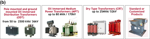
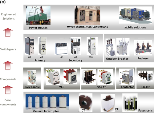
The main equipment and systems that make up the HTA are cables, transformers (Figure 10.1(b)), circuit breakers, load break switches, contactors, capacitors, filters, energy storage modules, current limiters, distribution control units, fuses, surge arresters and disconnectors. Among this equipment, medium-voltage switchgears may be a combination of the above components (Figure 10.1(c)). A typical apparatus weighs between 100 and 2000 kg. A switchgear is used both to de-energize equipment to allow work to be done and to clear faults downstream. This type of equipment is important because it is directly linked to the reliability of the electricity supply.
Medium-voltage switchgears concern the power networks supplied either in alternating current at voltages greater than 1 kV (or 1.5 kV direct current) and up to 52 kV (alternating current). (It is worth noting that according to the IEC, HTAs deal with nominal voltage (Vr) in the range of 1 kV < Vr ≤ 35 kV and HTBs (35 kV < Vr ≤ 230 kV) and extra-high- and ultra-high-voltage networks (>230 kV)). It provides the automatic protection of these systems against all incidents liable to disturb their operation, and it also performs on command the operations for modifying the system configuration in normal duty conditions. This switchgear differs from the low-voltage switchgear in the levels of voltage applied, the technical constraints it must meet, and its lifetime (longer than 20 years). Indeed, it has to withstand dielectric stresses, ensure the passage of current without excessive heating and without degradation of the contacts, be capable of functioning in severe atmospheric conditions (humid, marine and industrial pollution atmospheres), withstand major earthquakes and, above all, for the circuit breakers, be capable of interrupting all currents less than or equal to its interrupting capacity. Moreover, it must not require any maintenance throughout its lifetime.
Different systems are used to ensure the dielectric insulation of the medium-voltage switchgear: vacuum, air, liquid (vegetal and synthetic oils), gases (mainly sulphur hexafluoride (SF6)) and solid insulation made of epoxy or sheet moulding compound or bulk moulding compound; elastomers such as ethylene propylene diene monomer; or polysiloxanes (–Si–CH3) or thermoplastics such as polyhexamethylene adipamide ([NH−(CH2)6−NH–CO−(CH2)4−CO]n), polyphthalamide (–[–NH–R–NH–CO–C6H4–CO–]–), polycarbonate (–[–O–CO–O–R–]n–) or hybrids. The use of a fluorinated gas is justified by its very good dielectric strength, which makes the products more compact. However, the specific global warming potential of SF6 is approximately 23,000 times that of carbon dioxide. Its recovery at end of life is mandatory and follows a rigorous procedure. However, there is legislation that still does not apply to medium-voltage equipment.
10.5. End-of-life management of electricity distribution network equipment
A characteristic of medium- and high-voltage equipment (>1 kV) is the fact that they do not follow the directives of RoHS, ErP or WEEE (Hassanzadeh & Metz, 2012). The amount of such equipment is far less than that of low-voltage devices. Only proactive companies develop ecodesign, aiming, for instance, to ease the dismantling of their equipment. Such an approach will help to improve the economic viability of the end-of-life management of such equipment.
There is today a consensus among proactive companies to consider five periods in the environmental life cycle: manufacturing, distribution, installation, use and end of life. Joule losses and the corona effect always lead to the use phase being the period with the most impact. Such physical phenomena are, however, difficult to reduce and will need scientific and technical breakthroughs to do so.
The end of life also has driven much of the attention in research because the end-of-life period is easier to affect than decreasing the efficiency (mainly electrical consumption) consumption of the equipment. A product reaches the end of its lifetime in a variety of cases.
• The service life guaranteed by the manufacturer expires. Depending on the categories of the equipment, this lifetime varies from 20 to 40 years.
• The equipment is defective following a malfunction of the distribution network or a technical problem in the machine.
• The product is replaced because of modifications in the organization of the power network.
• The product is degraded during transportation or installation operations or through external causes such as fires or natural catastrophes.
In all these cases, the product is no longer fitted to fulfil its original functions. The choice of moving towards a recycling or reuse system after overhaul will depend on the condition of the apparatus, its value and the cost of maintenance. In general, overhauling the product is worthwhile for equipment that is slightly degraded or that has not undergone major electric shocks. The difficulty is assessing these products to find out the possibilities of upgrading. This is easier with apparatuses whose history is known or for which the worn parts are clearly identified. The rest of the apparatus is directed towards recycling systems.
10.6. Case study: managing the recycling of medium-voltage switchgear
To properly manage the recycling of the switchgear at the end of its lifetime, it is necessary to clearly define all the steps to be followed, from product recovery to material regeneration. For this purpose, a general approach for all of electrical and electronic devices and a specific guide for each device are needed. The general approach is to give the main directives to the actors participating in the end-of-life phase. Here we describe in detail the main steps in the management of medium-voltage switchgear, from the de-installation step to the final end use of the materials (Figure 10.3).
• De-installation: This operation must be performed by qualified personnel using appropriate protection. In all cases, checking that the device is disconnected from the power network and is not energized and does not contain any residual voltage is indispensable. In this way, checking that the loaded mechanical parts do not present any danger is vital.
In some cases, recovering the insulating oils and gases before transportation will be required. It is important to note that the manipulation of SF6 gas requires specific authorization (EC 842/2006 regulation of 17 May 2006 on specific fluorinated greenhouse gases). Each product containing insulating oil or gas is marked by a label indicating the quantity of insulator and the position of the recovery point.
Each de-installed product must be accompanied by a tracking sheet, which includes the reference of the device, its history and the operations performed. Specific events such as fires, technical failures or natural catastrophes must be included. This sheet follows the product until its regeneration.
• Transportation: Transportation must be carried out while following the safety and environment rules. A follow-up register must be filled in. The user is responsible for ensuring that this step is carried out smoothly. The recovered oils and gases must be sent to the specific processing facilities. The recovered quantities must be measured and recorded in the waste follow-up registers. It is important that the truck drivers be trained in the transportation of these substances.
• Collection: It is possible to temporarily collect products at the user's facility to optimize transportation to the dismantling centres. If this is not possible, the product will be dispatched directly for dismantling. Depending on the category of the device, it is important to follow the storage rules. The devices for internal use should be stored appropriately to protect them from corrosion.
• Dismantling: To date, there exists two possible methods for dismantling: depending on the country and the geographical location of the customers, manufacturers propose either to recover their equipment or to send them directly to local partner companies specializing in the management of electrical and electronic waste. These companies then are assisted by the manufacturer for the dismantling and recycling procedure. Should the customer choose other suppliers, it is essential to make sure of their qualifications and of the end use of the waste.
Before any dismantling operation, it is important to check the existence of a liquid or gas insulator. In this case, the recovery of these products is paramount.
This operation requires approval and dedicated installations, especially for SF6. Depending on the type of device, there exists an appropriate drainage procedure. Before the recovery of SF6 or the insulating oil, checking their chemical condition is advised. At all events, the devices that have sustained an electric arc or are heavily damaged will be drained into dedicated containers because the insulating products may be contaminated and harmful.
Dismantling may be carried out manually, semi-manually or automatically. It is possible to combine these three systems to optimize the operation for segregating components and materials. The objective is to recover the materials for recycling purposes. The choice of the type of dismantling depends on the design of the device, its composition and its cost. Manual dismantling is often more costly than automatic dismantling but presents the advantage of preserving the quality of the recovered materials (Huet, Aeschbach, Tschannen, Pohlink, & Bessede, 2004). A dismantling guide is often offered for medium-voltage products. This manual aims at dispatching devices to WEEE. The manual mode is used to separate the components joined by easy-to-detach fastenings such as screwing, positioning and torquing. The semi-manual mode (use of mechanical tools) is used to separate riveted, fitted and enclosed components. The automatic mode is used to detach cast, glued, welded or brazed assemblies. The choice of dismantling mode is linked to various parameters in addition to the fastening mode – the recycling compatibility of the assembled materials. When the materials are compatible, they do not need to be separated. This is the case for certain metals such as low-carbon steel for stamping and high–elastic-limit steel cold forming or certain thermoplastics such as polycarbonate and terephthalate polybutadiene.
If the quantity of recovered materials is very small, the priority will be given to crushing. It is possible to determine a reference price of recovered kilograms per minute per country. For example, in France, a kilogram of steel should be recovered in less than 1 min and a kilogram of copper in less than 3 min (Schneider Electrical, 2007).
When the quality of the recovered materials is very large, as for some metals (silver, stainless steel, steel, cooper and aluminium), it is preferable to proceed by manual dismantling. In some countries, manual dismantling costs are less than crushing. For example, the average cost of crushing for the whole range of materials in France is €100–150/ton, whereas the hourly labour cost in China is €15.
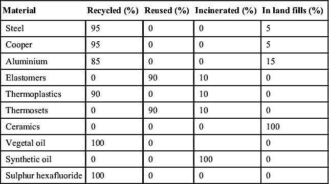
Concerning the end-of-use phase, the objective may be to optimize the reuse of the recovered materials. In order of priority, recycling is the first way, followed by the reuse of the material (as a load or for a secondary use), then energy extraction. Transfer to a burial facility is reserved for the very end of life or wastes that are difficult to reuse. To date, the recycle rate of European-made switchgears is greater than 70%. Table 10.1 presents the proposed end uses for the materials. The values presented in this table are mean values.
Extending the lifetime of medium-voltage switchgears beyond the initial lifetime is possible in some cases. In general, the wear of a product arises both from the functioning and from the degradation of some components. In this type of approach, it is important to think of the overhaul cost and the failure risk. To do this, the lifetime can be extended for equipment items whose price is greater than the cost of maintenance at end of life. Some medium-voltage cubicles may be suited to this kind of approach. The recovered device has to undergo expert assessment to determine the scope for return to operation. This assessment is based on a set of tests that may differ from one device to another. As an illustration, the following tests should be administered for a circuit breaker:
• Visual inspection of the equipment: number of operations performed, corrosion, wear, cracking
• Measurement of the open/close rates of the drive: open/close time, synchronization of phases, reset times
• Partial discharge test: evaluate interrupting performance
• Resistance measurement: wear of conductive parts.
Other tests may be required to check the working condition of the device. An overhaul could then enable a return to operation, usually with a limited lifetime. This path has not yet been thoroughly explored, given the guarantee to be offered for the reinstated devices. This is because any failures present high risks to the safety of the power networks.
The end-of-life management of medium-voltage electrical products is an area currently under development. To date, there exist no structures dedicated to this type of product. This is because these products have a long lifetime, and the existing quantities do not justify such a mobilization. However, the electrical equipment pool worldwide is extensive, and old equipment such as switchgears will reach their end of life in the near future. It is therefore important to prepare carefully and organize suitable systems for de-installation, collection, dismantling and recycling. For this reason, a dismantling guide should be compulsory for any medium-voltage equipment. A long period of work will remain to be accomplished afterwards to assist the customers and service suppliers in this end-of-life management approach. Beyond the scope of the end-of-life phase, customers may benefit from data that can also be used as a comparison guide for high- and medium-voltage equipment.
10.7. Meeting PEP and LCA requirements for electricity distribution network equipment
For any specific equipment, several steps should be rigorously followed to fulfil the goal of the PEP program. The PCRs document provides generic rules for writing the PEP. Electrical, electronic and HVAC and refrigeration equipment are allocated into specific categories such as switchgear and control gear, solutions and cable management, autonomous safety lighting, wire and cables, heating equipment, etc. In the switchgear and control gear solutions, there are three categories of products: passive products (e.g. circuit breakers), active products (e.g. temperature control devices) and enclosures (e.g. electrical cabinets).
With the increase of the scope of the PEP program, more categories will be added in the near future. New product-specific rules (PSRs) will be published in the near future with more details: standard reference, functional units, extrapolation rules, maintenance in use phase, and so on. According to the PSRs of equipment, the lifetime of the passive products and enclosures category during the use phase has been agreed on as 20 years, although for active products it is only 10 years. For nonpermanent passive products to simulate wattage losses during the use phase, only 30% of nominal current is taken into account and during only 30% of the lifetime of the product category, that is, 6 years and not 20 years. This is unlike permanent passive products, for which wattage losses are simulated at 100% of the lifetime but with 30% of nominal current.
Regarding the product studied, in addition to basic information (name and visual product), it is necessary to indicate the category to which the product belongs (indicated in the PSR) and the FU. In addition to LCA results, PEP provides information on product content and end-of-life aspects. The declaration of materials and substances in the PEP also follows specific rules. It is necessary to indicate in the document the total mass flow reference (of the product as well as the packaging and the products requested for installation). Plastics and metals, among others, are materials to be mentioned (expressed in percentage of weight of the total mass of the flow of reference). These can be broken down by group of substances or materials.
10.8. Case study: LCA of medium-voltage switchgear
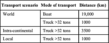
Regarding the phases to be considered of the environmental life cycle, there are five periods to be taken into account: manufacturing, distribution, installation, use and end of life. Considering the inventory of the flows, the cutting rule applies: the maximum mass of intermediate flows that can be not taken into account must be ≤5% of the total mass of the elementary flow (http://www.pep-ecopassport.org/docs/PEPPCRed2FR20111209.pdf (July 2012)). For example, under REACh, for equipment (an article) weighing 200 kg (packaging included), the mass of neglected parts must not exceed 10 kg when performing the LCIA. Moreover, transport related to each phase of the life cycle have to be taken into account (distance, type of transport). In the case of unavailability of data, penalizing average data were established under the PEP ecopassport and are to be used. These data are listed in Table 10.2.
Regarding the use phase, scenarios are described in the PSRs document. PSRs are additional rules specific to each of the categories of products, and they are part of the PCR (http://www.pep-ecopassport.org/docs/PEPPCRed2FR20111209.pdf (July 2012)) (Figure 10.4). For example, medium-voltage circuit breakers belong to the category Passive products. For this category the use scenario considered a useful life of 20 years and a load rate of 30% of rated current.
Concerning the calculation of environmental impact, the indicators used in the PEP ecopassport include a common set of mandatory indicators and optional indicators. Figure 10.5 describes the impact indicators taken into account. In the future, these indicators will be completed by additional impact indicators that take into consideration during market evolution. In particular, building impact indicators that are already standardized will be added to actual indicators to be more and more exhaustive.
Let us develop the example of a medium-voltage circuit breaker. In the field of medium-voltage vacuum circuit breakers there are at least three families of products:
• Air insulation
• Gas insulation
• Solid insulation.
Today, PEP ecopassport PCRs provide general rules on the PEP ecopassport. That is why we recommend giving more details in the PSR to be more accurate for a given product. For example, we recommend creating three different PSRs for each family of the above-mentioned switchgears (Figure 10.6).
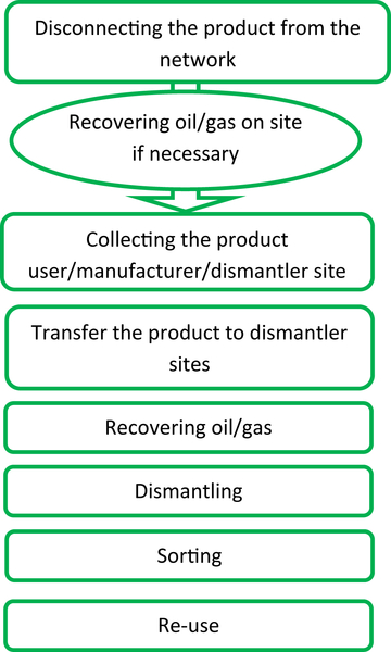
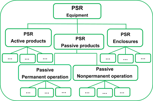
Figure 10.7 depicts seven key elements for the declaration of environmental profile conforming to the PEP ecopassport:
• LCIA according to ISO standard 14044 (ISO, 2006)
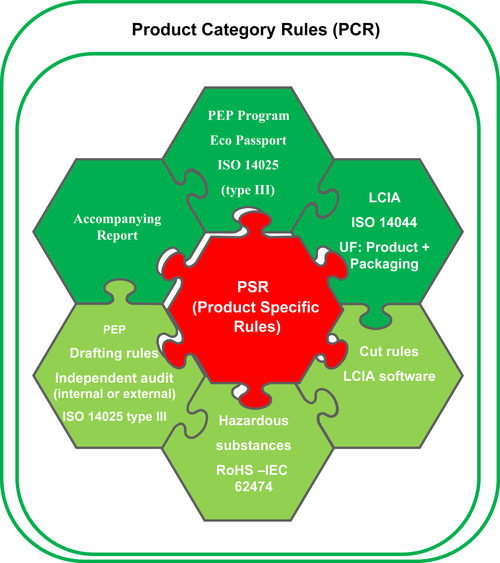
• Declaration of hazardous substances according to RoHS and IEC 62474
• Verification of the PEP by an independent party
• Report explaining the PEP elaboration and hypothesis chosen
• Declaration of PEP according to ISO standard 14,025 (ISO, 2006)
To follow these main key rules, even more specific PSRs will be created in the near future.
10.9. Future trends
Beyond cost, the technical performance of a product is no longer considered as the unique parameter of choice; environmental performance throughout the whole life cycle of the product also need to be considered. This implies knowledge of the environmental life cycle assessment and regulatory compliance to ensure that products follow the new laws, rules and regulations. In the case of electricity distribution network equipment, European directives and regulation (RoHS, ErP, WEEE, REACh) and IEC standards in the field of environment are the new driving forces of technological developments for proactive companies. These texts are difficult to read and often are subject to interpretation. However, they are intertwined in such a way that they complement each other. Furthermore, some countries such as China, Japan, Canada and Australia have adopted similar regulations, and others are under investigation. The generalization of such a regulatory framework and the use of IEC standards should eventually reduce the environmental impact of electricity network distribution equipment throughout its life cycle. PEP ecopassport, a fair environmental identity card, is a good answer to market need, in particular concerning the carbon footprint. The PEP ecopassport reflects the continuous improvement of products over time, transparent communication and combined relevant environmental information (11 environmental indicators) along a product’s value chain.
Beyond the scope of electricity network distribution equipment, the network distribution itself will experience major changes in the coming years. Indeed, total energy consumption is expected to double by 2050 (IEA, 2012) and electricity consumption by 2030 (IEA, 2012), greenhouse gas emission must be halved in the same time period (Intergovernmental Panel on Climate Change, 2012) and generation, transmission and consumption will need to become four times more efficient. Energy efficiency and renewability are the main routes to decreasing the worldwide emission of carbon dioxide (57% reduction of global carbon dioxide emissions will come from energy efficiency by 2030 (IEA, 2009)).
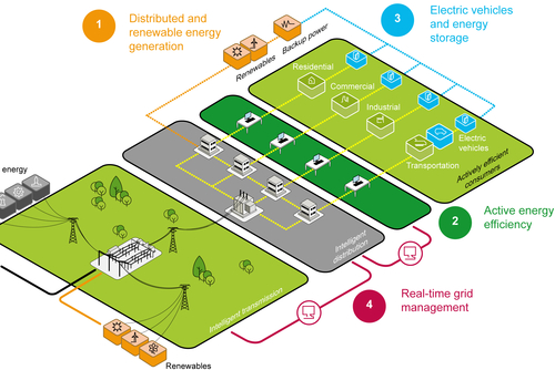
Renewable energies are essential today but still are difficult to integrate into energy mix. For instance, the intermittency difficulties associated with large-scale wind power, a mature technology, may be overcome but always at considerable cost and time. The conventional electric network designed around the world, that is to say, simple and linear, with centralized power generation and passive consumption, will gradually transform into a more sophisticated model, one that is interconnected and interactive: a smart grid, a fundamental re-engineering of the way electricity is used (Figure 10.8). The smart grid relies on new technology of information, with three main goals:
• increase the flexibility of operation of power systems based on enhanced measurement and control capabilities;
• optimize production and consumption of electricity to balance supply and demand for electricity in time or geography;
• ensure the safe operation of the network in the presence of decentralized intermittent electricity, including photovoltaic and wind.
Implementing integrated solutions for energy management in all industrial, commercial and residential buildings, which account for nearly three-quarters of global energy consumption, may save up to 30% of the final consumption. Intelligent energy management, that is, management of the network in real time, which also allows the consumer to anticipate and adapt supply, is the obvious quickest, easiest and most sustainable solution.
Concerning the electricity distribution network, losses are an inevitable consequence of the transfer of energy across networks. Current leakages increase over time because of the ageing of the equipment. On average, around 7% of electricity transported across French distribution systems is reported as electrical losses (Les dispositifs, 2014). Such reported losses are influenced by a number of factors, both technical and operational. Main technical losses occur from cables. Electrical conductivity is strongly related to impurities, and the use of primary metal casting is required. However, according to the US Geological Survey (2013), the reserves from the primary production of copper and aluminium will last 31 and 167 years, respectively (as of 2006). Also, the substitution of copper by aluminium is likely to increase in the coming years.
By monitoring the network, not only failures but also current leakages may be solved and possible damage anticipated. Intelligent distribution will facilitate the creation of a more responsive and more stable power supply.
List of acronyms
BT
low voltage
ERDF
Électricité Réseau Distribution France
HTA
medium-voltage network
HTB
high-voltage network
ErP
Energy-related Products
FU
functional unit
IEA
International Energy Agency
IEC
International Electrotechnical Commission
ISO
International Standard Organization
LCA
life cycle assessment
LCIA
life cycle impact assessment
PBT
persistent, bioaccumulative, toxic
PCR
product category rule
PEP
product environmental profile
PSR
product-specific rule
REACh
Registration, Evaluation and Authorization of Chemicals
RoHS
Restriction of Hazardous Substances in Electrical and Electronic Equipment
RTE
Réseau de Transport d’Électricité
SF6
sulphur hexafluoride
SVHC
substance of very high concern
TWh
terawatt hour
TWhe
terawatt hour of electricity
WEEE
Waste Electrical and Electronic Equipment
..................Content has been hidden....................
You can't read the all page of ebook, please click here login for view all page.