Outside World
The Network Is the Computer™
(company slogan)
Sun Microsystems, Inc.
Some have predicted that computers will “disappear” in the future. This is not some neo-Luddite forecast but rather the suggestion that computers will continue to shrink in size and increase in number such that all of our computing functions will be ubiquitous and pervasive. That is, they will disappear into our everyday articles. The idea is that there will be many embedded computing systems distributed throughout things such as our clothes, entertainment devices, home appliances, packaging, public infrastructure, and so on — making the need for conventional, general-purpose computers moot. The strength of these small devices, however, will not be in their individual ability but rather in their collective functionality. Hence, these small systems will need to communicate with many kinds of devices and via a variety of networking protocols.
Until recently, embedded systems designers were often forced to use very light weight, custom codes and protocols because hardware capabilities of the target machine were limited. Today, more capable hardware allows the embedded systems programmer to use much more sophisticated protocols, such as the Universal Serial Bus (USB) and even the Internet Protocol (IP) that underlies the World Wide Web. Indeed, standard protocols such as HTTP and free software such as Linux and a Web server such as Apache are becoming increasingly important for even the simplest electronic devices.
There are several compelling reasons to use these standards. First, using existing protocols means that a custom protocol does not need to be created. Furthermore, using existing protocols often means that reference software already exists — which, if it can be reused, can save a considerable amount of development cost. Indeed, the cost savings include the initial investment in developing the software for the embedded system, future improvements, and the client software used to communicate with the embedded system. For example, consider a power distribution unit (PDU) in a server rack containing an embedded Web server. If this is the case, then a system administrator only needs a Web browser to control power to her servers. In general, building an embedded system that uses standard protocols whenever possible increases interoperability in the new era of ubiquitous, persuasive embedded systems.
Of course, computer networking is itself a huge subject and multivolume books have been written about it — there is no way one chapter can provide a comprehensive treatment. However, we can survey the basic technologies starting with the low-speed serial technology and protocols that emerged in the 1970s and have been common in embedded systems up to the latest high-speed technologies and sophisticated protocols used in high-end systems today. Rather than be comprehensive, the goals of this chapter are to enumerate the different technologies and protocols, discuss the common use cases, and provide references to more detailed information.
7.1 Point-to-Point Communication
A decade ago, a subset of the RS-232 serial communication standard was the de facto mechanism to connect embedded systems to other computing devices [Electronics Industries Association, 1969]. It was often used for debugging during development and user configuration in the field. This asynchronous serial communication protocol required three wires — transmit, receive, and a common ground. It was simple and the IC device that implements the protocol (a UART — a Universal Asynchronous Receiver/ Transmitter) was inexpensive.
RS-232 interfaces have been almost completely replaced with Universal Serial Bus (USB) [USB Implementers Forum (USB-IF), 2010a,b] interfaces in modern consumer electronics because USB offers higher speeds, more capabilities, and a smaller physical form factor than RS-232. Unfortunately, with these advantages comes considerable complexity in terms of hardware and software. Using USB on a client device usually requires either buying a controller chip or integrating a USB controller into the FPGA fabric. However, the biggest disadvantage for using USB on educational embedded systems projects is the drivers needed on the host PC. Given that all modern operating systems include the necessary drivers and terminal emulation software for RS-232-like terminal devices and the examples presented in this book only require terminal access to the embedded system, there is no need for the extra overhead of USB.
7.1.1 RS-232
Among existing embedded systems, the most common serial communication protocol in use is RS-232. This standard has evolved significantly over time and is the “COMx” port that used to be standard on desktop PCs in the 1980s and 1990s. It began as a protocol to connect dumb terminals (Data Terminal Equipment or DTE) to acoustic modems (Data Communication Equipment or DCE). The standard was not developed for peers to communicate but rather there is a specific orientation. To attach two DTEs together one has to use a “null” modem that effectively cancels two DCEs by interchanging the transmit and receive lines (i.e., the transmit of one end is connected to the receive of the other and vice versa). Along with these two lines, a common ground is also required. The standard goes on to define many more pins but most embedded systems only use this subset. (Sometimes hardware flow control is used as well and that includes two more wires.)
The basic hardware component to support the RS-232 is called a UART — a Universal Asynchronous Receiver/Transmitter. This device is essentially a parallel-to-serial shift register. The protocol involves the transmission of a series of spaces and marks, which represent 0 and 1, respectively. The protocol defines voltages that range from +25 to −25 V with a voltage between +3 and +25 V representing a space and −3 to −25 V representing a mark. Note that this is drastically different from the 0 to 5 V that is common in Transistor-Transistor Logic (TTL) so often line drivers (a separate IC) have to be used to convert TTL signals to RS-232 signals.
Because there is no common clock between the two devices, a receiver does not know when a message may begin. The protocol specifies that the transmitter holds a space (say, +15 V) until it is ready to transmit a word. The transmitter then sends one mark (to signal that a message is coming) followed by data followed by an optional parity bit. The protocol specifies that the message must be terminated by one or two stop bits, which are spaces. At this point the transmitter holds a space on the line until the next message is ready to be transmitted.
The biggest issue one has to deal with when using RS-232 is that all of the options have to be agreed upon from the beginning. Both sides have to be configured in advance to know the baud rate; how many data bits are in a message; if odd, even, or no parity encoding is used; and how many stop bits to expect. This set of parameters is often abbreviated in a format such as 9600 8N1, which represents one of the most common RS-232 parameter sets: 9600 baud with 8 data bits, no parity bit, and 1 stop bit.
Newer protocols such as USB include negotiation on things such as signal rates so that the fastest transfer rate that both the host and the client can support is used.
7.1.2 Other Low-Speed Communication
Between RS-232 and USB in terms of complexity, a number of simple protocols are used to connect components within an embedded system. Two common examples of these are Interintegrated Circuit (abbreviated IIC or I2C) and Serial Peripheral Interface (SPI). Both of these protocols share the concept that one device is the master (or host) and that there are one or more slaves (or peripherals).
The I2C technology was developed by Philips Semiconductor, and the complete bus specification is available on the Web [Philips Semiconductor, Inc., 2009]. I2C uses two wires: serial data and serial clock. SPI uses four wires: chip select, serial clock, data in, and data out. Both are commonly used to interface temperature or voltage sensors in embedded systems. While there are some trade-offs of which the low-speed communication protocol is better in terms of power usage and physical space, the decision to use one protocol over the other is typically driven only by what slave devices you need to connect in this embedded system. If the best analog-to-digital converter for your project uses an SPI protocol, then you should include an SPI master in your system.
This also leads to one significant advantage of using an FPGA for an embedded system over off-the-shelf microprocessors. If the project requires an I2C, an SPI, two UARTs, Ethernet, and other interfaces, it is very easy to add these components to an FPGA-based design. However, if you were to use an off-the-shelf microcontroller, it may be difficult to find a chip with exactly the right number and kind of interfaces required.
7.2 Internetworking Communication
7.2.1 Concepts
As just mentioned, the range of technologies and protocols that encompass what is called “computer networking” is enormous. Within the field, individuals often specialize into very different subfields, ranging from Web application programming to Internet router specialists. Also contributing to the large knowledge base is the fact that different technologies can be mixed and matched. For example, when people think Ethernet, many assume TCP/IP. However, other protocols run over (and co-exist with TCP/IP) on an Ethernet network. Furthermore, TCP/IP can also be used on local area networks other than just Ethernet. This section focuses specifically on the Internet Protocol (IP) and the most common higher level protocols that use Transmission Control Protocol (TCP). The chief distinction is that IP provides a technology-independent packet-based mechanism to send information, whereas TCP is used to deliver an in-order stream of information from one host to another. The other sometimes used component of this family is UDP, which provides a TCP-like application interface but is oriented around packet-based communication.
The Internet Protocol was designed to span multiple computer networks, all of which may have different characteristics (in terms of reliability, speed, and technical specifications). To manage this complexity and to maximize the reuse software, the networking functionality is often divided into layers (and the collection of layers is called a network protocol stack). Figure 7.1 shows the network protocol stack for a typical TCP/IP system.

Figure 7.1 A network protocol stack.
In networking terms, a single machine is called a host and we assume that there are two applications running on two hosts that wish to communicate. If the two hosts are directly connected to one another, then all the layers of the protocol stack are probably overkill. However, very often it is the case that the two hosts are not directly connected and so intermediate devices are needed to relay information. Figure 7.2 shows two hosts, A and B, that are communicating through an intermediate device. If the two hosts are on the same network, the intermediate device is called a switch (or, in some cases, a bridge). If the communication is across two different technologies, or two different networks, the intermediate device is called a router. Finally, a gateway is a router that generally connects a network to the rest of the Internet. (If the address of a host is known but its location is not, the usual behavior is to send the packet to a gateway device that forwards it on.)

Figure 7.2 Two hosts communicating with TCP/IP.
The network protocol stack is organized by functionality. The lowest level — the physical layer — is responsible for generating a real-world, physical signal. It might use a line driver to create physical voltages (such as +15 and −15 V, as is the case of RS-232) or a transceiver to pulse light into a fiber-optic cable. The components that create these signals are often designated PHY (pronounced fy and rhymes with pie) and these components may be part of a Platform FPGA (as is the case with the multi-gigabit transceivers on a Virtex 5) or a separate integrated circuit. The PHY does not know anything about data, its format, or timing. Its sole job is to translate a computer’s digital signals to the analog world.
At this layer, direction is important so the transmitters (denoted TX) are usually distinguished from the receivers (RX). Also, because it is so closely associated with the physical world, these components are almost exclusively physical, analog components. The receiver and transmitter together are collectively known as the network interface.
As Figure 7.1 suggests, it is not uncommon to have multiple network interfaces. Indeed, many devices today might support multiple network interfaces. For example, unique devices such as Earth-orbiting satellites typically have at least one network interface to communicate with ground stations and may have another one to talk with the satellite’s payload, typically an instrument of some sort. A more down-to-earth example would be a modern mobile phone. It typically will have one network interface to talk with a cell tower. But increasingly, phones have a second Bluetooth interface that is used for short-range wireless connections between the phone and a headset.
Before we leave the lowest layer, it is worthwhile to make mention of network topology. The network topology is nothing more than the underlying point-to-point relationship between each host on the network, which — as any reader who has made it this far into the book recognizes — can be modeled as a graph. Previously, most topologies are regular, which means that from the point of view of any vertex in the graph, the relative positions of every other vertex in the network are the same. However, this regularity is an artifact of the way we have built networks for the last 50 years. That is, engineers have imposed a structure to make the system manageable. As we lurch toward ubiquitous, embedded computing, this regularity breaks down. For example, with mobile phones the network is now extended by many little “one-hop” links over a Bluetooth connect. Likewise, the space-based example of the previous paragraph can be extended to an emerging commercial technology of launching nanosatellites. These satellites are typical low mass — which makes them easy to launch — but limit what kind of instruments can fly as payload. So one current proposal suggests that we launch constellations of these satellites that work together. Because their exact, relative position is difficult to maneuver, they naturally form ad hoc networks where the edges cannot be determined before the satellites are in orbit. Dealing with the network that arises from circumstances is handled at a high layer but it occurs because we have multiple network interfaces.
Onward! We have what is known as the (data) link layer. In Figure 7.1, the link layer is depicted as being closely integrated with the physical layer. This is because some technologies (such as the early versions of Ethernet) in essence required that it be implemented in hardware. This layer had the responsibility of not only communicating with the physical layer, but also observing the physical layer for anomalies or errors. For example, the earliest versions of Ethernet relied upon a common media — a coax cable — as a shared resource for communication. The purpose of the link layer is to allow two directly connected hosts to communicate. It manages a link between two hosts in terms of checking for transmission errors and flow control.
Often the link layer is divided into upper and lower halves. The lower half — called the Media Access Controller (or MAC) — is responsible for talking to the PHY. In modern versions of the Ethernet standard, several well-defined interfaces exist between the MAC and the PHY. The original MII is TTL/CMOS (0 to +5.5 V) signals and was common in 10/100 (FastEthernet) networks. GMII and RGMII were introduced for Gigabit Ethernet because additional bandwidth was required (RGMII is a variation that uses half the number of data lines but transfers data on both rising and falling edges of the clock). Most recently is Serial Gigabit Media Independent Interface or SGMII, which uses high-speed serial transceivers style of communication between the lower half of the link layer and the PHY. Details of these protocols are not critical to the Platform FPGA designer, but one has to be aware of them because often the MAC is implemented in the FPGA and PHY is off-chip so one has to match the right protocol to the off-chip hardware. Logical Link Control (LLC) is the upper half of the link layer. It is responsible for flow control between two nodes in the network.
Above the link layer is the network layer. The purpose of this layer is to provide connectivity beyond two directly connected hosts. For example, in Figure 7.1, there are three network devices. In order for A to communicate with C, A transmits packets to B via the link layer. Those packets are passed to the network layer, which makes decisions about how to advance the packet toward its destination. Often this means retransmission through the link layer to another device. The most common network layer is the Internet Protocol (the IP in TCP/IP). This standard includes the usual data packet plus control packets used to manage the network. At this layer, communication can bridge different physical communication channels. For example, a packet can arrive over a link layer that interfaces to a serial communication channel and forward the packet to a link layer that interfaces to Ethernet. Novel’s IPX is another example of a network layer protocol.
However, applications usually do not interface with the network layer directly. In the Open Source Interface (OSI) model, there are several layers in between the application and the network layer ISO/IEC JTC1 (1984). However, the best known approach is the Internet Protocol and it has one layer — the transportation layer. There are multiple interfaces to the transport layer associated with IP. The most common is the Transportation Control Protocol or TCP. This protocol provides an error-free end-to-end stream service. That is, data are written to the stream on one end and arrive (in order) at the other end. These data may have been broken up into packets, fragmented, reassembled, duplicated, and traversed different routes along the way but the network layer hides all of that and provides a reliable data path for the application. Another network layer interface is the User Datagram Protocol (UDP). This provides unreliable, packet-based communication between applications. It uses the Internet Protocol, and while a user datagram will always be delivered intact, it may have been fragmented and reassembled en route. As mentioned, this is an unreliable service and some datagrams might not be delivered without notice to the application.
7.2.2 Application Interface
Application access to the network layer is most often through the Berkeley socket interface. Our goal is not to provide a comprehensive guide here, rather it is to provide enough information about a basic server and client to jump start any project that needs a custom protocol. Also, a basic knowledge of how an Internet application works will help demystify existing applications and their configuration files.
The simplest Internet application is a TCP/IP client/server. The basic idea is that the client will initiate contact with a server by referring to the service’s IP address and a port number. Because a port is associated with no more than one server on a specific machine, this provides a unique address for a server. Not every machine will associate the same port number with same server, but most common servers have a conventional port number. For example, an HTTP server is usually found on port 80, a secure shell server uses 22 by default, and so on. Sometimes the port will be explicitly changed to avoid unwanted, automated probes of a system. A file /etc/services documents (potential) services on a specific host and a library call getservbyname allows a program search for a port associated with a service on the local machine. By using the socket interface described next, the operating system on the client’s machine and the operating system on the server’s machine set up a two-way communication. The network protocol stack described previously provides an error-free stream- (versus packet-) based communication channel.
The programming interface uses file descriptors, just like many of the system calls we are already familiar with (open/read/write). However, one can use the C library call freopen to get an fprintf or fscanf style interface.
A typical application-specific server application will ordinarily start during the boot process. It generally does not require root privileges unless it uses a port below 1024.1 The server’s first task is to request a specific port from the OS and configure it. This is accomplished with the socket, bind, and listen system calls. The way they are typically used is illustrated in Listing 7.1. The
first system call (socket) creates a file descriptor to manage client connections to the server. The next two, bind and listen, tell the operating system what port the server would like to be associated with (bind) and sets a queue length (listen). In this example, five clients can line up to access the server before the OS immediately rejects client requests. (We will explain the htons call shortly.)
The next step is for the server to wait for a client connection. This is typically performed inside of an endless loop. Listing 7.2 illustrates the basic algorithm. The accept system call will block the server process until some client has initiated a connection. The first argument is the file descriptor that was just configured and a structure to hold the client’s address. The return value is a new file descriptor that is used for communication with this client. (The sockfd can then be used again in another accept system call.) When communication with the client has finished, the file descriptor is closed and the communication channel is formally torn down.
Listing 7.3 shows the client application also uses the socket system call to create a socket file descriptor. Unlike the server, this is the only file descriptor needed to communicate with the server. To get initiate communication with the server, the client (1) creates the socket and gets the server IP address with a gethostbyname library call, which is copied to the socket address structure. The
last step is to call the connect system call, which will set up the communication channel. On return, the sockfd file descriptor can be used to read and write to the server.
In the host and client, we use a library call, htons, which handles the byte order of an integer. The name is short for host to network (16-bit integer). Likewise, there is an htonl, which is short for host to network (32-bit integer). When the host machine uses the same byte ordering as the network standard, these functions do nothing. If they differ, the subroutines reverse the byte order. There is also an ntohs and ntohl used for converting network standard to host byte ordering of integers, if needed.
An important variant of the client/server application described here is a UNIX dæ mon. In this system, the client operates exactly the same. What is different is how the server is started. As described previously, we assume the server was started when the machine was booted. This is perfectly appropriate for an application-specific embedded system. However, for many UNIX-based machines, we do not want to start a server for every single service that the host might have a server for. This led to “super server,” which is a single application whose job is to set up a socket for a set of servers (essentially doing the steps illustrated in Listing 7.1). When a client appears on any of the ports that the super server is watching, the super server accepts the connect and then starts the real server with the communication socket as the standard input/output. In doing so, the server process only uses system resources when there is a client requesting a connection. It is easy to build a server that, based on a command line argument, will start either as a dæ mon or as an ordinary server. There are multiple implementations of the “super server.” The original was called inetd (Internet dæ mon super server). The package xinetd is a popular variation. Busybox also has a simple implementation as well. We mention this because both styles of server are common. Also, it is worth pointing out the difference between the /etc/inetd.conf and the /etc/inittab. The latter is for starting processes at boot; the former launches Internet servers on demand.
Once a communication channel is established, any data can be streamed across this channel. Even though binary data can be transmitted, older protocols were often 7-bit ASCII based and organized around “lines” that were terminated with a newline. Newer protocols tend to use a syntax similar to extended Mark-up Language (XML). For very simple protocols, the former can be easy to parse (read line by line from the file descriptor). For more complex, structured data, XML works very well but usually requires additional software to parse the format. Regardless, any data sent over a communication channel using Berkeley sockets as described here are plaintext. That is, data are not encrypted and it is very easy for an anonymous, third party to view these data. In some cases, such as public Web sites, there is no need for privacy but if there is any sensitive information that needs to be transmitted, encryption is essential.
On a final note, very often a custom protocol is not needed. There are a number of well-defined protocols with open source software available that will support many of the common tasks. Moreover, they often have the benefit of using encrypted transmission or at least offer an encrypted variant. We review the most common ones for embedded systems next.
7.2.3 Higher Level Protocols
By itself, the IP protocol stack is convenient but does not provide much more than connectivity for an embedded system. However, on top of these protocols (most often over TCP but sometimes UDP), several higher level protocols have evolved. Many of these protocols were not formally standardized but interoperability was achieved through an informal “request for comment” (RFC) memo and the sharing of source code. Often the first software implementation became the reference code. The low-level details of these protocols are beyond the scope of this chapter. What is important for the embedded systems designer is to know what protocols exist, their high-level characteristics, and what is required to use them. Hence, we want to spend a little bit of time surveying the protocols found most often in embedded systems.
Telnet
One of the earliest protocols developed using TCP/IP is called telnet. It was proposed in RFC15 in 1969 and then extended over time; it was one of the first standards adopted by the Internet Engineering Task Force (IETF), which formalized the RFC process. Telnet uses TCP/IP to provide an (insecure) bidirectional stream between a client and a telnet server (or dæ mon) running on the embedded device. This server can either ask for authentication (username/password) or simply start a command line based configuration or diagnostic application. This protocol uses port 23 on a standard UNIX implementation and has been largely replaced by Secure Shell (ssh and sshd) for workstations and servers because telnet passes all data (including usernames and passwords) unencrypted over the network. However, for embedded systems — where a password might not be needed — this is a great, lightweight protocol. For this reason, it is often the first protocol implemented in a “network-ready” embedded system. For example, adding an Ethernet interface to a printer makes it a “network printer.” Now that the printer is on the network, one could use telnet to check toner levels, manually set the network configuration, etc. Again, it must be stressed that telnet should not be used for sensitive data.
The telnet server is implemented as Internet dæ mon. On an embedded Linux project, the first step is to make sure the network interface has been configured. This is usually done when the system is booted (see next section). Next, we need to tell the network super server to watch for connections to this service. Most sample inetd configuration files have this required line commented out. Simply edit /etc/inetd.conf, find the line below, and remove the leading pound sign.
#telnet stream tcp nowait root /usr/sbin/telnetd telnetd -i
If a client tries to connect to port 23, the inetd process will accept the connection and then start the “real” telnetd.
World Wide Web
The World Wide Web (WWW) evolved out a sequence of efforts in the late 1980s and early 1990s to make scientific (and other) data publicly accessible. Much earlier Internet efforts resulted in the File Transfer Protocol (FTP), which, like telnet, was a simple, insecure mechanism used to transfer files from one host to another over TCP/IP. With the addition of no-password accounts, this allowed the transmission of raw data but there was no imposed structure to these data. The consumer of these data had to know the file name and directory organization conventions used by the producer. What the World Wide Web did was introduce a server protocol, Hyper-Text Transfer Protocol or HTTP, that transmitted files to a file in the Hyper-Text Mark-up Language or HTML. The HTML files included display as well as references to non-HTML data files. This allowed a client to not just copy or display the raw data but present it to the user. This quickly led to innovations that allowed the server to interact with a user client. The “client” for World Wide Web servers is commonly known as a Web browser.
This technology is a great boon for embedded systems developers. Custom protocols — whether over a direct communication link such as RS-232 or the Internet — mean that the embedded systems designer has to develop both the server (running on the embedded system) and the client. This puts the designer in the untenable position of either supporting the client on multiple potential hosts or limiting the embedded systems potential market. With HTTP and HTML, the designer simply has to follow the prevailing standards and their embedded system works with any Web browser.
There are a number of Web server implementations. Perhaps the most common is Apache. It is a vast project that has spawned a number of supporting projects. It is feasible to cross-compile Apache and run it on a Platform FPGA design. However, there have been numerous implementations that run the gamut from purely academic exercises to implementations carefully designed to run on limited resource-embedded systems. Often, embedded systems do not have the resources to support a full Apache server. There are many lightweight servers such as lighttpd, http://www.lighttpd.net/, and thttpd, http://www.acme.com/software/thttpd/, that may be more appropriate for an embedded system. Also check with your FPGA vendor for servers that are already included with their tools.
Simple Network Management Protocol
Perhaps the next most important network protocol for embedded systems is the Simple Network Management Protocol (SNMP). It is also unique because it is one of the few common protocols based on the UDP (packet-based versus TCP’s stream based) transport layer.
The protocol was originally developed to interrogate and manage autonomous network devices such as routers and switches. For example, one might want to know the number of packets sent and received on a particular switch port or the device as a whole. Alternatively, one might want to know what speed a port autonegotiated to when a host was connected. SNMP allows an administrator to do this through a client over IP. It includes a “call back” mechanism whereby the network device can inform the administrator that some event has occurred. It turns out that the design was general enough to support a wide range of equipment, and a number of different network-ready devices use the protocol. For example, one can monitor the current flowing through a Power Distribution Unit using SNMP.
Network File System
The Network File System (NFS) protocol has been used for more than two decades to make a remote filesystem (running on a server) appear like a local filesystem. To use this protocol requires a certain degree of trust between the server and the client. As such, it is generally not useful for embedded systems in the field.
However, it can be extremely useful during development. The end product might be limited in the amount or speed of secondary storage. Having the system under test on a network and configured to mount a home directory or the root filesystem from a server in the lab is a huge benefit. Once the operating system is configured and stable, the embedded system can be left running continuously. On a workstation, the application work can be repeatedly cross-compiled and tested without (manually) copying the executable between workstation and embedded system. Moreover, it allows the filesystem to grow arbitrarily large while under development. Then, when everything is working, it can be cleaned up to fit the space constraints of the embedded system’s native filesystem.
Network Time Protocol
One of the servers that the DHCP protocol can provide is a Network Time Protocol (NTP) server. (The DHCP protocol is used to set up an embedded system on an unknown network; it is described next.) This server (along with an array of public servers on the Internet) gives the embedded system an opportunity to determine the time automatically. In the 1970s and 1980s, Video Cassette Recorders (VCRs) all across the world endlessly flashed 00:00 for the time. No matter how simple the interface — it was difficult to get users to set the time, let alone reset it after power was lost! But there are many situations when knowing the time is a very useful thing for an embedded system. Compiling an NTP client that gets the time (and periodically checks it for consistency) is a valuable software feature.
Secure Socket Layer
To make plaintext network traffic secure, there is the Secure Socket Layer (SSL). With SSL, a client and server connect via a handshaking protocol to configure the secure connection. This is done through the exchange of shared public keys and certificates, which are used to generate a session key. Once connected, the client and server can communicate securely through the encoding and decoding of the encrypted data based on the session key. Open source library implementations, such as OpenSSL, can provide an encryption layer between the application and the transport layers. OpenSSL is maintained by a large community of developer volunteers and is based on the SSLeay library. Because OpenSSL is open source, its use requires acceptance of the dual license, which covers both conditions of the OpenSSL License and the original SSLeay license.
7.2.4 Operating System Configuration
Most of the time, an embedded system will want to bring up a network interface (i.e., configure and activate it) when the system boots and bring it down (deconfigure) during an orderly shutdown of the system. Traditionally, this has been accomplished with two commands: ifconf.01ptig and route. The first configures a network interface and requires one argument followed by one or more options. The second command updates the kernel’s network routing table. However, to do so means that the embedded systems developer has to know in advance what network the device will be on, the assigned IP address, a gateway to the rest of the Internet, etc. So, in practice, these commands are handy during development but in the field, high-level protocols (such as DHCP described later) are needed.
Generally, these commands are being phased out. As networking has become more complex, two programs (called ip and tc) have evolved to handle that complexity, advanced routing, and traffic shaping. The ip command, which comes as part of the iproute2 package, can do everything that ipconf.01ptig can and more. The interface also directly supports a number of network configurations that didn’t exist when ifconfig was written. If you don’t want to install the whole iproute2 package, Busybox provides an ip command that makes porting start up scripts from desktop machines a little easier.
The Dynamic Host Configuration Protocol (DHCP) and BOOTP protocols allow a deconfigured network interface to broadcast a request for information about its network parameters. These protocols rely on a server existing somewhere on the network that watches for such broadcast messages. With Ethernet networks, every network interface has a MAC address, also known as its hardware address. Ethernet equipment providers acquire blocks of these addresses and each product receives a unique address. Based on the server configuration and the hardware address found in the broadcast Ethernet packet, the server can (1) assign an IP address, (2) choose to assign an address from a pool of available addresses, or (3) ignore the request. The information that the server can provide can be as simple as the IP address (and length of time, after which it has to broadcast another request). But it can also provide other useful network information, such as a netmask and a gateway host to the Internet. It also usually provides the IP address of other useful servers: a domain name server, a network time server, and so on.
Nowadays, DHCP is a requirement for embedded systems. Without it, the end user would have to know and be able to enter the network information. In the case of embedded systems destined for a home network, end users might not have any idea how their home router works. (They just followed the three-step setup and it “just worked.”) In the case of mobile devices, the end user might not know anything about the coffee shop’s network. In both cases, the DHCP server exists — it’s just up to the embedded system to use it.
Finally, it is worth mentioning the ifupdown package. It provides two commands — ifup and ifdown — that read a /etc/network/interfaces configuration file. It still uses the primative (ifconfig and route) commands but has three advantages: (1) if there are multiple interfaces, all of the information about how to set up the network is collected into one configuration file, (2) it integrates nicely with dynamic changes — like someone plugging in a USB wireless network interface, and (3) the package “knows” about many of these low-level networking systems.
Chapter in Review
Two decades ago, relatively few embedded systems had networking or communication requirements. Simple serial protocols were sufficient for configuration and sharing of data. Nowadays, embedded systems often have multiple network interfaces and, out of market necessity, have to support a rich set of complex high-level protocols. With Open Source implementations available, embedded systems designers do not have to understand the details of these protocols. However, designers do have to understand how the pieces fit together and when it is appropriate to use existing software. The goal of this chapter was to provide an overview of this enormous topic. First, we discussed a few of the common point-to-point serial communication protocols such as RS-232 and I2C. Next, we described the Internet Protocol and the role of various protocol layers. If an application needs a custom protocol, an IP server needs to be developed. A bare bones simple server was presented. Finally, several existing protocols and commands used to configure the network were presented.
Practical Expansion
Outside World
Communication off-chip can be a big part of embedded systems design. FPGAs have shown their capabilities for years as being a significant player in integrating off-chip communications. However, until more recently, the role FPGA played in the communication has been somewhat limited. As designers shift their focus away from the glue-logic support to platform support of FPGAs, there comes increasing support for off-chip communication. These practical pages discuss two such types of off-chip communication. First is high-speed communication in the form of Xilinx RocketIO through the use of high-speed serial transceivers. The second topic focuses on low-speed communication with the use of an integrated I2C bus within a system. These two examples are meant to highlight the similarities and differences in high-speed and low-speed designs.
7.A High-Speed Serial Communication
More recently, FPGA vendors have started to include high-speed serial transceivers on the FPGA as diffused IP. These transceivers allow FPGAs to interface directly with emerging communication standards such as PCI-Express, Serial ATA, InfiniBand, and 10 Gigabit Ethernet. Serial interfaces require fewer traces on a PCB, which has allowed smaller and more dense PCB layouts. However, the serial traces have to be designed with tightly controlled impedences for the transceivers to operate correctly. There is extra complexity on the FPGA logic side of the transceiver, as the components have many more configuration settings than a typical I/O pad.
7.A.1 RocketIO
The Xilinx Virtex series of FPGAs from the Virtex-II Pro through the Virtex-6 have included some form of RocketIO high-speed serial transceiver. These transceivers have maximum data rates of 3.125 Gbps on the Virtex-II Pro to 11 Gbps on some Virtex-6 FPGAs. Typical devices have between 8 and 24 of these full-duplex transceivers on a chip, which can be used to connect several high-speed devices or to create custom networks of FPGAs. While it is possible to directly instantiate the transceiver primitive in a design, Xilinx recommends using the Coregen utility to abstract the complexities of the transceiver and provide the user with a simpler data link layer interface.
7.A.2 Aurora Example
Aurora is a data link layer protocol provided by Xilinx. It provides the user with a simple stream or frame-based interface to send and receive data. Aurora can also be used to bond several transceivers together to make a single higher bandwidth link. Aurora is able to handle transceiver-specific operations such as inserting clock-correction sequences into the data stream.
As an example, consider connecting two ML-510 development boards via their Personality Module (PM) interface present on each board. Eight of the 24 GTX RocketIO transceivers on the FPGA are connected to the PM interface. We can use these eight transceivers — each transmitting and receiving data at 5.0 Gbps — to achieve 40 Gbps of bandwidth in each direction, a total of 80 Gbps of bandwidth between the two FPGAs.
To achieve this, launch the CoreGen wizard. Start a new project and select the xc5vfx130t-2ff1738 FPGA. Generate an Aurora 8B10B core (found under Communication & Networking — Serial Interfaces) to have eight lanes, with each lane being 4 bytes wide. We will use the 250-MHz SGMII reference clock. Select the streaming interface to reduce the complexity of the logic needed to send data between the two boards. Note that framing is a convenient way to represent packets from a network layer but streaming is better for simple data-flow style applications. The first page of the coregen wizard is shown in Figure 7.3.

Figure 7.3 Aurora configuration.
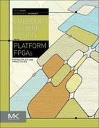
The second page of the wizard lets the user select which GTX transceivers to use for the eight lanes of the aurora channel. From the ML-510 schematic you can determine that the transceivers connected to the personality modules are GTX_X0Y3 through GTX_X0Y6 (each GTX tile contains two transceivers). Map the lanes to transceivers as shown in Figure 7.4. Coregen will generate an entire system design that uses this aurora core. The top level of this example project can be found in:
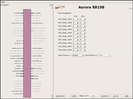
Figure 7.4 Lane to transceiver mapping.
component_name_example_design.vhd
The following sections describe the important components of this example project.
7.A.3 LocalLink Interface
The Aurora component uses the LocalLink interface as described in Section 6.A.3 to send and receive data from the user logic — in this case a simple data generator and error detector. As we selected the streaming interface the start-of-frame and end-of-frame LocalLink signals are not used. Also notice that in this example the data signal is 256 bits wide instead of the standard 32.
7.A.4 Clock Correction
It is common in serial communication to only send data between the transmitter and the receiver, not a copy of the clock. In low-speed communication such as RS232, both sides agree on a data rate and generate their own internal reference clocks. However, in high-speed serial communication it is more common for the receiver to infer the reference clock from data by examining transitions on the data line itself. This system works well, except if long periods go by without a transition; the receiver’s inferred clock can drift from the transmitters.
We use two methods to handle this problem. First we use data encoding like 8B10B, which takes 8 bits of data from the user and encodes it as 10 bits with more transitions to send across the wire. Second, we periodically stop sending user data and insert a clock correction sequence with many transitions to make it easy for the receiver to infer the correct clock. Xilinx recommends sending these clock correction sequences at every 10,000 clock cycles. The cc_manager component in the example design handles the insertion of these sequences.
7.A.5 Error Testing
When debugging a communication system like this it is very useful to have a component that generates a stream of data along with a second component that receives that data and checks for errors. Xilinx has provided these components in the example design: frame_gen and frame_check. These components use a 16-bit linear feedback shift register with an XNOR feedback to generate a pseudo-random data sequence to be transmitted and received.
7.A.6 Loopback
This example may be infeasible to build and test on a student’s budget. It would require two ML-510 development boards and a custom PCB that would connect the two personality module connectors with controlled impedance transmission lines between the transceivers on each board. However, you can test this on just one ML-510 without a custom PCB by using the loopback feature of the transceivers. The transceivers have two internal loopback paths, either before or after the final output driver, to allow testing on a single FPGA. You can set the loopback_i signal in the example design to any nonzero value to use these loopback paths instead of requiring a second ML-510.
7.B Low-Speed Communication
While the first section focused on high-speed serial communication, the focus in this section is to support a popular low-speed communication protocol, namely I2C. We use the I2C bus to read and write to a connected EEPROM that is physically located on the Xilinx ML510 development board. Once we have the ability to interact with this device, it will become academic to interface with other devices on the I2C bus.
7.B.1 Generating the Hardware Base System
Using the Base System Builder wizard from within XPS we can quickly generate a hardware base system for the Xilinx ML510 with the Virtex 5 FX130T FPGA. Create the following base system:
| Board Selection | Xilinx Virtex 5 ML510 Evaluation Platform Revision C |
| System Configuration | Single-Processor System |
| Processor Configuration | 400-MHz PowerPC processor with 100-MHz Bus |
| Peripherals | refer to Figure 7.5 |
With this short example we do not need to include every peripheral in the system. This will save us greatly on our build times, allowing us to try different implementations without spending a lot of time sitting idle by the computer. Selecting the I2C EEPROM peripheral in the base system builder wizard will instantiate and instance the Xilinx component IIC_EEPROM. Because the wizard has already instantiated the component, we will walk through the Xilinx XPS project files to highlight the changes that would have been made had we needed to add the I2C component to the project without the aid of the wizard.
Figure 7.5 Peripherals needed for the I2C EEPROM example on the Xilinx ML510 development board.
User Constraints File
We begin with the user constraints file located within the project directory:
% <XPS_PROJECT>/data/system.ucf
Looking at the schematic for the ML510 development board we can see that the I2C bus consists of two pins, SDA and SCL, for the data and clock lines, respectively. On the ML510 development board this EEPROM is connected to the I2C bus while the I2C bus connects to the FPGA via pins K8 and L7. We can specify through the user constraints file that SDA will connect to K8 and SCL will connect to L7.
Net fpga_0_IIC_EEPROM_Sda_pin LOC=K8 | IOSTANDARD=LVCMOS33;
Net fpga_0_IIC_EEPROM_Scl_pin LOC=L7 | IOSTANDARD=LVCMOS33;
Microprocessor Hardware Specification File
In order for the system to interface with the SDA and SCL pins of the I2C bus that have been set in the user constraints file, we must first specify at the top of the MHS file the pin connections and directions. This will allow us to use these pins to connect to the I2C component shortly.
PORT fpga_0_IIC_EEPROM_Sda_pin = fpga_0_IIC_EEPROM_Sda_pin, DIR = IO
PORT fpga_0_IIC_EEPROM_Scl_pin = fpga_0_IIC_EEPROM_Scl_pin, DIR = IO
Now we are able instantiate our component. In the MHS file this is done with the following syntax:
BEGIN xps_iic
PARAMETER INSTANCE = IIC_EEPROM
PARAMETER C_IIC_FREQ = 100000
PARAMETER C_TEN_BIT_ADR = 0
PARAMETER HW_VER = 2.02.a
PARAMETER C_BASEADDR = 0x81600000
PARAMETER C_HIGHADDR = 0x8160ffff
BUS_INTERFACE SPLB = plb_v46_0
PORT Sda = fpga_0_IIC_EEPROM_Sda_pin
PORT Scl = fpga_0_IIC_EEPROM_Scl_pin
END
A few points can be made from this declaration. First off is the address map of the component. We are connecting this device to the same PLB that the PowerPC is connected to. Reading and writing from this address range (0x81600000–0x810ffff) provide us with the ability to read and write effectively to the EEPROM. That is, the I2C EEPROM component acts as a bridge between the system on-chip and the external world. The second point to make is that the two pins, SDA and SCL, are connected from this component through the top-level MHS pin declarations defined previously and finally connected to the user constraints file pin declarations. This same strategy can be employed for connecting external components to the FPGA.
Microprocessor Software Specification File
Finally, we need to specify within the MSS the software libraries that support our interfacing with the I2C component. This is necessary to allow the SDK to generate the necessary address space and supporting interface that we will discuss shortly.
BEGIN DRIVER
PARAMETER DRIVER_NAME = iic
PARAMETER DRIVER_VER = 1.16.a
PARAMETER HW_INSTANCE = IIC_EEPROM
END
Next we must Export Hardware Design to SDK, which will synthesize and generate the system’s bitstream along with creating the SDK project and launching the SDK.
I2C Software Application
Once the SDK launches we must generate a new software platform. Because we are not including Linux in this example, we can generate a simple standalone software platform. We will also need to generate a new C application using this stand-alone software platform.
Within our C application we must include a set of libraries to support interfacing with the I2C bus.
#include <stdio.h>
#include <string.h>
#include “sleep.h”
#include “xbasic_types.h”
#include “xparameters.h”
#include “xiic.h”
#include “xiic_l.h”
#include “xgpio_l.h”
#include “xtime_l.h”
Next, we can set some C #define values for more human readable code and try to eliminate any magic numbers in our code.
#define START_ADDR 1024
#define END_ADDR 2047
#define IIC_BASEADDR XPAR_IIC_EEPROM_BASEADDR
#define IIC_SIZE (END_ADDR-START_ADDR+1)
#define IIC_ADDR 0xA0
#define IIC_DELAY 5000 /* useconds */
At this point we can use a struct to set up what will be the contents of the EEPROM. Initially, the EEPROM will be empty; however, we can write new contents based on the storage needs of the device. In this example we will set some board information that could be used later to identify the board, say, during a boot procedure.
typedef struct iic_eeprom_struct {
/* Generally used parameters */
/* 0x000 to 0x010 Plain text ID of which board */
char which_board[17];
/* 0x011 to 0x015 Plain text Board Rev (A, B, C, etc) */
char board_rev[5];
/* 0x016 to 0x01A Plain text minor board rev (001, 002, etc) */
char minor_board_rev[5];
/* 0x01B to 0x02E Plain text which FPGA is on the board (main FPGA if multiple) */
char which_FPGA[19];
/* 0x02F to 0x037 Plain text Serial Number of board */
char board_sn[9];
/* 0x038 to 0x044 Plain text MAC Address for this board */
char board_mac_id[13];
/* 0x045 to 0x050 Plain text last date that tests were run (DD-MMM-YYYY) */
char last_test_date[12];
/* 0x051 to 0x05C Plain text Manufacture Date (DD-MMM-YYYY) */
char manufacture_date[12];
/* 0x05D to 0x06D Plain text Manufacture ID (Name) */
char manufacture_id[17];
/* 0x06E to 0x080 Plain text set to ‘Xilinx Virtex-X Based MLxxx’ (?19?) */
char tested_before[19];
}iic_eeprom_struct;
Next, we will want to set some function prototypes to support easier read and write access to the I2C bus.
/* Function Prototypes */
/* For IIC Read / Write */
static void send(Xuint32 addr, Xint8 *data, Xuint32 len);
static void receive(Xuint32 addr, Xint8 *data, Xuint32 len);
Finally, we can write the actual main function that will read and set the values of the EEPROM on the I2C bus.
int main() {
char *eeprom_ptr;
iic_eeprom_struct *eeprom;
/* Pointer to the base of the EEPROM Struct */
eeprom_ptr = (char*)eeprom;
/* Read EEPROM for all current contents */
receive(START_ADDR, eeprom_ptr, IIC_SIZE);
/* Print out contents of EEPROM */
printf(“Board ID: ”, eeprom->which_board);
printf(“Board Rev: ”, eeprom->board_rev);
printf(“Minor Board Rev: ”, eeprom->minor_board_rev);
printf(“Which FPGA: ”, eeprom->which_FPGA);
printf(“Board SN: ”, eeprom->board_sn);
printf(“Board MAC ID: ”, eeprom->board_mac_id);
printf(“Last Test Date: ”, eeprom->last_test_data);
printf(“Manufacture Date: ”, eeprom->manufacture_date);
printf(“Manufacture ID: ”, eeprom->manufacture_id);
printf(“Test Before: ”, eeprom->test_before);
/* Write new contents to EEPROM Structure */
eeprom->last_test_data = “01-JAN-2010”;
/* Write out all contents to EEPROM */
send(START_ADDR, eeprom_ptr, IIC_SIZE);
printf(“Program Complete ”);
return 0;
}
In order to support both reading and writing across the I2C, we must include the read and write subroutines.
/***************************************************************
** function: send
** purpose: Write data across I2C
** input: addr - Address to Write on I2C buss
** data - Data to be written to address (addr)
** len - length of data to be written
**************************************************************/
static void send(Xuint32 addr, Xint8 *data, Xuint32 len) {
Xint8 sendBuf[34];
Xuint32 pos, wlen;
Xuint32 ret;
wlen = 32;
for (pos=0; pos < len; pos+=32) {
if ((len - pos) < 32)
wlen = len-pos;
sendBuf[0] = (Xint8) ((addr+pos) >> 8);
sendBuf[1] = (Xint8) (addr+pos);
memcpy(&sendBuf[2], &data[pos], wlen);
ret = XIic_Send(IIC_BASEADDR, IIC_ADDR>>1, sendBuf, wlen+2, XIIC_STOP);
usleep(IIC_DELAY);
}
}
/***************************************************************
** function: receive
** purpose: Read from EEPROM
** input: address (addr), data pointer (data) and length (len)
** output: Data read from EEPROM stored at data pointer address
**************************************************************/
static void receive(Xuint32 addr, Xint8 *data, Xuint32 len) {
Xint8 address[2];
Xuint32 ret;
address[0] = (Xint8) (addr >> 8);
address[1] = (Xint8) addr;
ret = XIic_Send(IIC_BASEADDR, IIC_ADDR>>1, address, 2, XIIC_STOP);
ret = XIic_Recv(IIC_BASEADDR, IIC_ADDR>>1, data, len, XIIC_STOP);
}
7.B.2 Testing the Design
Now all that is necessary is to save and program the application to the FPGA. This can be done by either creating the ACE file as we did in Section 1.A or through the SDK and a JTAG as was done in Section 3.A. If this is the first time the program runs, the EEPROM may not be initialized to any values. If that is the case you will need to write more than simply the last_test_data value. Of course, you are not limited to this information. In fact, you can program the contents you would like to the EEPROM. Because the EEPROM is nonvolatile, when the FPGA loses power and reboots the contents will remain in the memory. As stated earlier, this can be very helpful when designing systems.
Exercises
P7.1. Contrast RS-232 and USB in terms of end-user experience and in terms of design complexity.
P7.2. How does a TCP/IP server differ from a UNIX dæmon?
P7.3. How is the physical layer different from the rest of the layers in the protocol stack?
P7.4. What does the link layer do?
P7.5. What does the network layer do?
P7.6. Why does a TCP/IP server use two socket file descriptors instead of one?
References
1. Electronics Industries Association. EIA standard RS-232-C interface between data terminal equipment and data communication equipment employing serial data interchange Geneva, Switzerland: International Organization for Standardization; 1969.
2. ISO/IEC JTC1. Open system interconnection — OSI reference model (ISO 7498) Geneva, Switzerland: International Organization for Standardization; 1984.
3. Philips Semiconductor, Inc. The I2C-Bus specification, Version 2.1 2009; In: http://www.semiconductors.philips.com/acrobat/various/I2C_BUS_SPECIFICATION_3.PDF; 2009.
4. USB Implementers Forum (USB-IF). USB 2.0 specification 2010a; In: http://www.usb.org/developers/docs/; 2010a.
5. USB Implementers Forum (USB-IF). USB 3.0 specification 2010b; In: http://www.usb.org/developers/docs/; 2010b.
1This was a weak form of security employed when there were just a handful of Internet hosts and the administrators of hosts could be trusted but not necessarily individual users. Now it is simply a legacy requirement.