
Chapter Ten. Shafts
Chapter Objectives
Learn how to use the Design panel to draw shafts
Learn how to add retaining ring grooves to shafts
Learn how to add keyways to shafts
Learn how to add O-ring grooves to a shaft
Learn how to add pin holes to a shaft
Learn how to use the Content Center to add retaining rings, keys, O-rings, and pins to shafts
Introduction
The tools on the Design panel can be used to draw many different styles of shafts. Figure 10-1 shows a uniform shaft with chamfered ends that was created using the Shaft tool located on the Power Transmission panel under the Design tab. Shafts may also be created by extruding a circle, but the Shaft tool allows features such as keyways and retaining ring grooves to be added to the shaft.

Figure 10-1
Uniform Shafts and Chamfers
Exercise 10-1 Drawing a Uniform Shaft with Chamfered Ends
The shaft is to be Ø1.00 × 4.00 in.
![]() Create a new drawing using the Standard (in).iam format.
Create a new drawing using the Standard (in).iam format.
![]() Click the Design tab and select the Shaft tool located on the Power Transmission panel.
Click the Design tab and select the Shaft tool located on the Power Transmission panel.
See Figure 10-2.
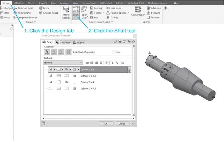
Figure 10-2
The Shaft Component Generator dialog box will appear. See Figure 10-3.
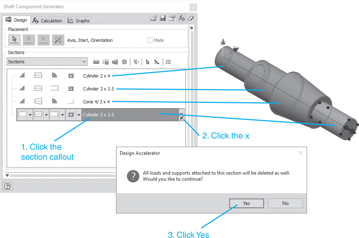
Figure 10-3
The Shaft Component Generator dialog box shows a shaft made of four sections. These sections can be manipulated or deleted as needed, making it easier to create a shaft than if you had to start from scratch.
Exercise 10-2 Deleting a Shaft Section
![]() Move the cursor onto the Shaft Component Generator dialog box and click the shaft section callout to be deleted.
Move the cursor onto the Shaft Component Generator dialog box and click the shaft section callout to be deleted.
The section’s heading will be highlighted.
![]() Click the X box in the lower right corner of the section’s name.
Click the X box in the lower right corner of the section’s name.
A check box will appear.
![]() Click Yes.
Click Yes.
The selected section will be deleted. See Figure 10-3. Repeat the procedure deleting both the Cone and 3 × 3.5 Cylinder sections. Retain the 2 × 4 Cylinder section. See Figure 10-4.
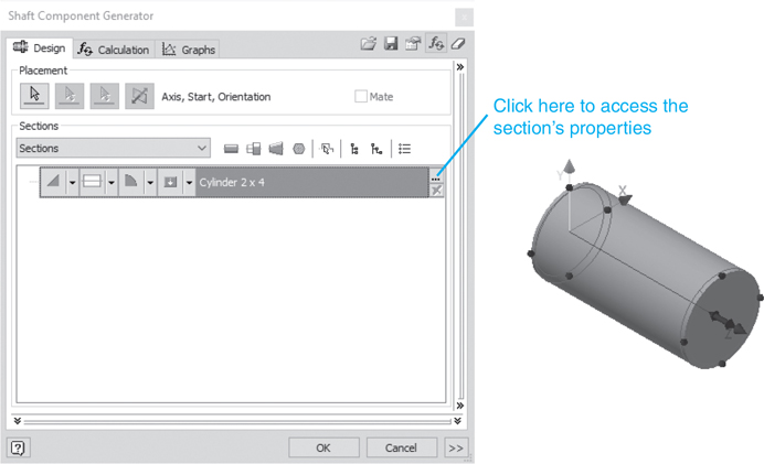
Figure 10-4
Exercise 10-3 Defining the Cylinder’s Diameter and Length
![]() Click the Section Properties box.
Click the Section Properties box.
The Cylinder dialog box will appear. See Figure 10-5.

Figure 10-5
![]() Click to the right of the default diameter value.
Click to the right of the default diameter value.
An arrowhead will appear.
![]() Click the arrowhead.
Click the arrowhead.
A list of options will appear.
![]() Click the Values option. A listing of standard shaft diameter values will cascade down.
Click the Values option. A listing of standard shaft diameter values will cascade down.
See Figure 10-5.
Note
The existing value could be deleted from the cylinder box and new values typed in.
![]() Select the appropriate diameter.
Select the appropriate diameter.
In this example, a value of 1 in was selected.
![]() Repeat the procedure for the shaft length.
Repeat the procedure for the shaft length.
In this example, a length of 3 in was selected.
See Figure 10-6.
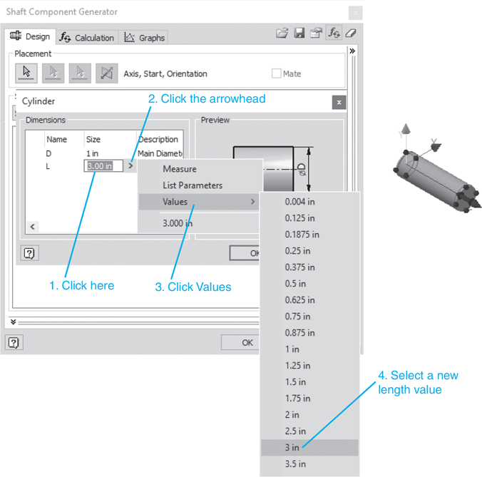
Figure 10-6
![]() Click the OK button on the Cylinder dialog box. See Figure 10-6.
Click the OK button on the Cylinder dialog box. See Figure 10-6.
Note
Do not click the OK button on the Shaft Component Generator dialog box until the cylinder has been completely defined. If you do, Inventor will create a second shaft adding the chamfers. If this happens, delete the incomplete shaft.
Exercise 10-4 Creating Chamfers
![]() Click the First Edge Feature box.
Click the First Edge Feature box.
See Figure 10-7.
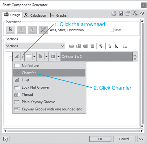
Figure 10-7
![]() Select the Chamfer option.
Select the Chamfer option.
The Chamfer dialog box will appear. See Figure 10-8.
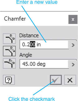
Figure 10-8
![]() Enter the chamfer values.
Enter the chamfer values.
In this example, a value of .200 in × 45° was entered.
![]() Click the checkmark.
Click the checkmark.
A preview of the chamfers will appear.
![]() Click the Second Edge Feature box and create a chamfer of the same size on the right edge of the shaft.
Click the Second Edge Feature box and create a chamfer of the same size on the right edge of the shaft.
See Figure 10-9.
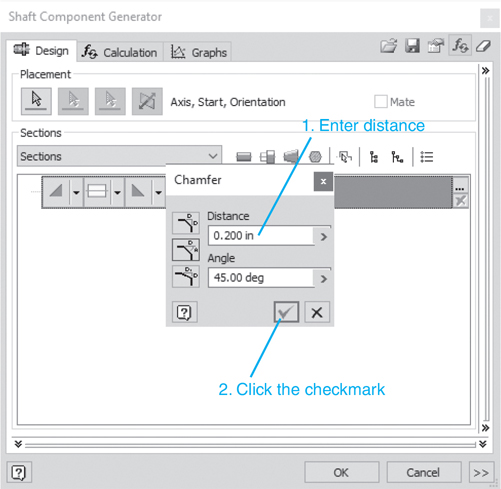
Figure 10-9
Note
The preview of the shaft that appears on the screen will show the size and location of the chamfers.
![]() Click the checkmark.
Click the checkmark.
![]() Click OK.
Click OK.
A preview of the chamfers will appear on the shaft.
The File Naming dialog box will appear.
![]() Click OK.
Click OK.
A grayed picture of the shaft will appear on the screen.
![]() Click the left mouse button.
Click the left mouse button.
Figure 10-10 shows the finished shaft.
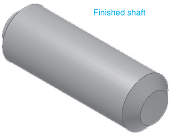
Figure 10-10
Shafts and Retaining Rings
Retaining rings are used to prevent longitudinal movement of shafts. Grooves are cut into the shafts and the rings fitted into the groves. Both internal and external rings are available.
Used to prevent longitudinal movement of a shaft. The ring fits into a groove cut into the shaft.
For this section, grooves will be cut into a Ø20 shaft to match the requirements of an ANSI B 27.7M external retaining ring.
The Content Center is used to determine the required diameter and width of the groove required by the ANSI B 27.7M retaining ring.
![]() Create a new drawing using the Standard (mm).iam format.
Create a new drawing using the Standard (mm).iam format.
![]() Click the Place from Content Center tool.
Click the Place from Content Center tool.
![]() Click the + sign next to the Shaft Parts heading.
Click the + sign next to the Shaft Parts heading.
![]() Click the Circlips option, click the External option, click the ANSI B 27.7M ring, then click OK.
Click the Circlips option, click the External option, click the ANSI B 27.7M ring, then click OK.
See Figure 10-11. The ANSI B 27.7M dialog box will appear. See Figure 10-12.
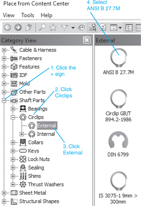
Figure 10-11

Figure 10-12
![]() Select a shaft diameter of 20.
Select a shaft diameter of 20.
![]() Click the Table View tab.
Click the Table View tab.
![]() Scroll across the table until the Groove Diameter and Groove Width values are revealed.
Scroll across the table until the Groove Diameter and Groove Width values are revealed.
See Figure 10-13. Note that the Groove Diameter value is 18.85 and the Groove Width is 1.2.

Figure 10-13
![]() Click OK.
Click OK.
A retaining ring will appear on the screen.
![]() Click the mouse to create a second ring, and press the <Esc> key.
Click the mouse to create a second ring, and press the <Esc> key.
Park these rings at the side of the drawing screen for now. They will be added to the shaft once it is created. See Figure 10-14.

Figure 10-14
To Create the Shaft
![]() Click the Design tab, and select the Shaft tool. The Shaft Component Generator dialog box will appear. Create a Ø20 × 40 shaft.
Click the Design tab, and select the Shaft tool. The Shaft Component Generator dialog box will appear. Create a Ø20 × 40 shaft.
![]() Click the Section Features box and select the Add Retaining Ring option.
Click the Section Features box and select the Add Retaining Ring option.
See Figure 10-15. The selected 20 ANSI B 27.7M retaining ring reference will automatically be selected. See Figure 10-16.
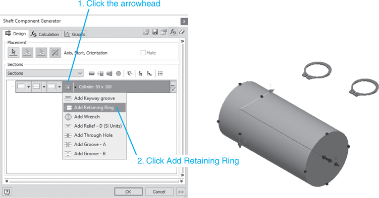
Figure 10-15
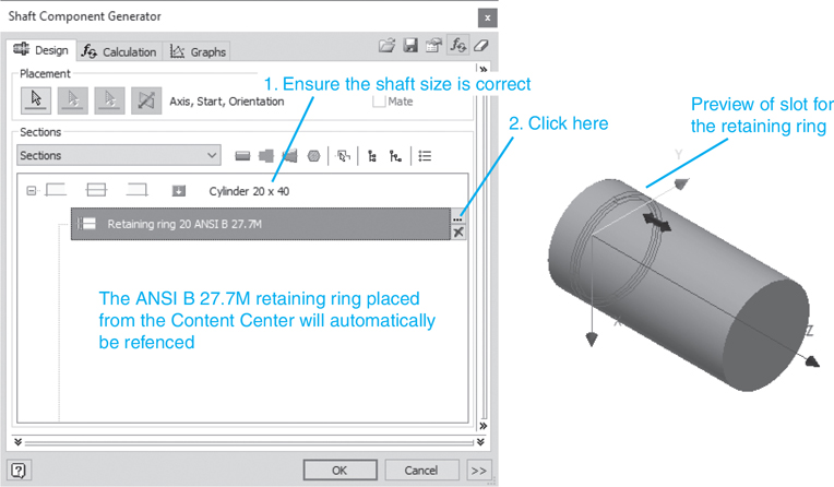
Figure 10-16
![]() Click the Retaining ring 20 ANSI B 27.7Mcallout and click the Feature Properties box.
Click the Retaining ring 20 ANSI B 27.7Mcallout and click the Feature Properties box.
![]() The Retaining Ring Groove dialog box will appear. See Figure 10-17.
The Retaining Ring Groove dialog box will appear. See Figure 10-17.

Figure 10-17
![]() Set the Positionfor Measure from second edge and the X value to 3.000.
Set the Positionfor Measure from second edge and the X value to 3.000.
A preview of the groove will appear. The 3.000 value was selected to locate the ring 3.000 mm from the end of the shaft.
![]() Click OK.
Click OK.
![]() Click the Feature Properties box for the retaining ring.
Click the Feature Properties box for the retaining ring.
See Figure 10-18.

Figure 10-18
The Retaining Ring Groove dialog box will appear. See Figure 10-19.

Figure 10-19
![]() Click the Feature Properties box and set the Position for Measure from second edge and the X value to 3.000.
Click the Feature Properties box and set the Position for Measure from second edge and the X value to 3.000.
A preview of the groove will appear. The 3.000 value was selected to locate the ring 3.000 mm from the end of the shaft.
![]() Click OK.
Click OK.
The File Naming dialog box will appear.
![]() Click OK.
Click OK.
The newly created shaft will appear with the previously drawn retaining rings. See Figure 10-20.

Figure 10-20
The first retaining ring created will be grounded, as indicated by a pushpin next to the ring’s callout in the browser box. Inventor always grounds the first component entered in a new assembly. We wish to remove the grounding from the retaining ring and ground the shaft.
![]() Access the browser box area and right-click the grounded retaining ring.
Access the browser box area and right-click the grounded retaining ring.
See Figure 10-21.

Figure 10-21
![]() Click the check mark next to the Grounded option.
Click the check mark next to the Grounded option.
The pushpin icon will disappear. The ring is no longer grounded.
![]() Right-click the shaft callout and click the Grounded option.
Right-click the shaft callout and click the Grounded option.
The shaft is now grounded. This can be verified by clicking the + sign to the left of the shaft’s callout. There should be a pushpin next to the Shaft:1 callout. See Figure 10-22.
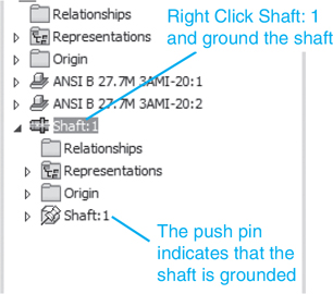
Figure 10-22
Add the rings to the shaft.
![]() Click the Assemble tab and use the Constrain tool to locate the retaining rings on the shaft.
Click the Assemble tab and use the Constrain tool to locate the retaining rings on the shaft.
Hint: Use the Insert tool and align the edge of the retaining rings with the edge of the grooves.
Figure 10-23 shows the retaining ring mounted on the shaft.
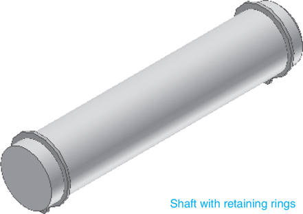
Figure 10-23
Shafts and Keys
Keys are used with shafts to transfer rotary motion and torque. Figure 10-24 shows a hub that has been inserted onto a shaft with a square key between the hub and shaft. As the shaft turns, the motion and torque of the shaft will be transferred through the key into the hub.
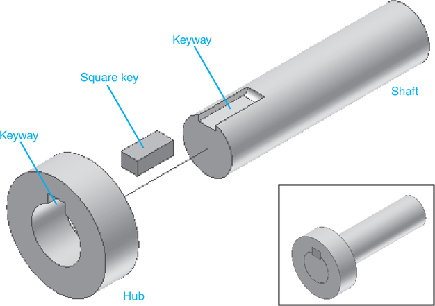
Figure 10-24
There are five general types of keys: Pratt and Whitney, square, rectangular, Woodruff, and Gib. See Figure 10-25.
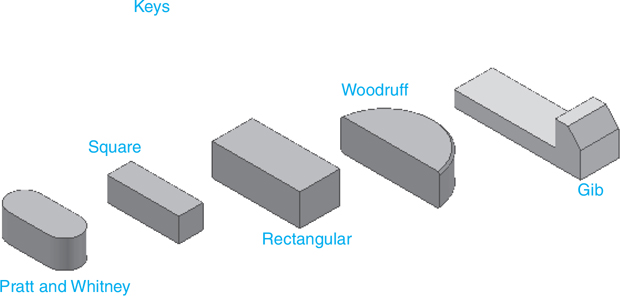
Figure 10-25
Square Keys
The following exercise will place a keyway in a Ø30 × 60 shaft. A rectangular DIN 6885 B key will be used. In an actual design situation, the key selected would be based on load shaft speed and shaft size considerations.
Exercise 10-5 Drawing a Keyway on a Shaft
![]() Start a new drawing using the Standard (mm).iam format.
Start a new drawing using the Standard (mm).iam format.
![]() Create a Ø30 × 60 shaft with no end features.
Create a Ø30 × 60 shaft with no end features.
![]() Right-click the mouse and click the Place from Content Center option.
Right-click the mouse and click the Place from Content Center option.
See Figure 10-26.
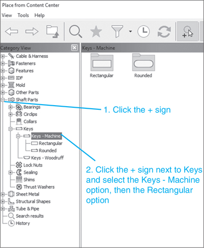
Figure 10-26
![]() Click Shaft Parts, Keys, Keys - Machine, and select the Rectangular option.
Click Shaft Parts, Keys, Keys - Machine, and select the Rectangular option.
The Rectangular key options will be shown. See Figure 10-27.

Figure 10-27
![]() Select the DIN 6885-1B key.
Select the DIN 6885-1B key.
The DIN 6885-1B dialog box will appear. See Figure 10-28.

Figure 10-28
![]() Select the Shaft Diameter range 22 – 30.
Select the Shaft Diameter range 22 – 30.
Note that the width × height of the key is listed as 8 × 7, and that the key’s nominal length is 18.
![]() Click the Table View tab and record the specified keyway values.
Click the Table View tab and record the specified keyway values.
The required keyway depth is 4, and the keyway groove length is 22. See Figure 10-29.

Figure 10-29
![]() Click OK and add a rectangular key to the drawing.
Click OK and add a rectangular key to the drawing.
Now, create a Ø30 × 60 shaft.
![]() Access the Shaft tool from the Design tab.
Access the Shaft tool from the Design tab.
The previous shaft data will appear on the screen. These data could be erased and a new shaft created, but Inventor allows you to easily modify an existing shaft using dynamic inputs.
![]() Delete the retaining ring values and one of the two Ø20 × 40 shafts by clicking the X boxes on the right side of the callouts.
Delete the retaining ring values and one of the two Ø20 × 40 shafts by clicking the X boxes on the right side of the callouts.
See Figure 10-30. Note the brown filled circles at each end of the cylinder. These are the dynamic inputs for changing the diameter and length of the shaft.
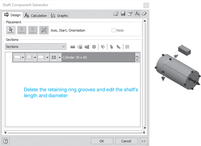
Figure 10-30
Tip
Ensure that no chamfers or end rounds have been included on the regenerated shaft. If they have been, enter a No feature option for both ends of the shaft.
![]() Click one of the dynamic arrows on the YZ plane and drag the shaft to a new diameter of 30.
Click one of the dynamic arrows on the YZ plane and drag the shaft to a new diameter of 30.
![]() Use the dynamic arrows to change the length to 60.
Use the dynamic arrows to change the length to 60.
See Figure 10-31.
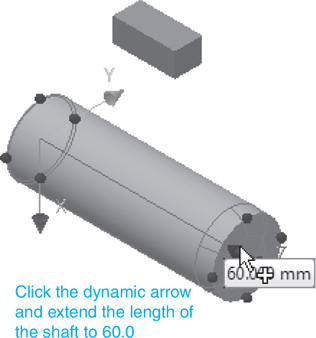
Figure 10-31
Tip
The dynamic inputs are preset to specific increments. If you need a shaft size that is not included in the preset list, click the Cylinder box and enter the desired values.
![]() Click the Second Edge Features box and select a Plain Keyway Groove option.
Click the Second Edge Features box and select a Plain Keyway Groove option.
See Figure 10-32. A default keyway will be added to the shaft. This keyway will be modified to fit the selected 8 × 7 × 18 rectangular key.
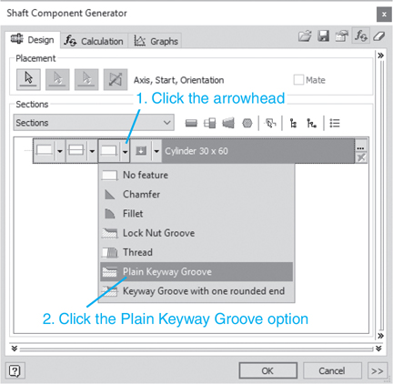
Figure 10-32
![]() Click the Second Edge Features box again.
Click the Second Edge Features box again.
The Plain Keyway Groove dialog box will appear. See Figure 10-33.

Figure 10-33
![]() Enter the appropriate values.
Enter the appropriate values.
In this example T = 4.00, L = 25.000, and B = 8.000. The length of the keyway could be any number greater than 18. The angle value is used to position the keyway. In this example, a value of 90° was entered.
Note
A 1 × 45° chamfer will automatically be added unless you enter a 0 value for Z.
![]() Click OK.
Click OK.
The Shaft Component Generator dialog box will appear.
![]() Click OK.
Click OK.
The File Naming dialog box will appear.
![]() Click OK.
Click OK.
Figure 10-34 shows the shaft with a keyway and the shaft assembled with the 8 × 7 × 18 key.

Figure 10-34
This section shows how to draw shafts and keyways using the tools on the 2D Sketch Panel and the Part Features panel bar.
Exercise 10-6 Drawing a Keyway Using the Sketch and Extrude Panel Tools
Figure 10-35 shows a Ø30 × 60 shaft drawn by first drawing a Ø30 circle using the Circle tool from the Draw panel under the Sketch tab, and then extruding to a height of 60 using the Extrude tool from the Create panel under the 3D Model tab. Draw a keyway that is 8 wide, 4 deep, and 18 long with end radius equal to 4.
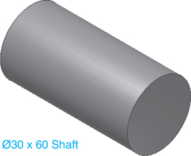
Figure 10-35
![]() Create a work plane tangent to the edge of the shaft.
Create a work plane tangent to the edge of the shaft.
![]() Create a new sketch plane on the work plane and draw an 8 × 22 rectangle. The 22 value includes the 4 needed to create the radius at the end of the keyway.
Create a new sketch plane on the work plane and draw an 8 × 22 rectangle. The 22 value includes the 4 needed to create the radius at the end of the keyway.
See Figure 10-36.
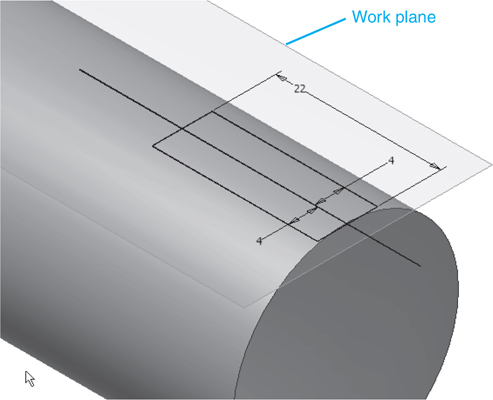
Figure 10-36
![]() Use the Cut option on the Extrude tool to cut out the keyway.
Use the Cut option on the Extrude tool to cut out the keyway.
![]() Draw an R4 radius at the end of the keyway.
Draw an R4 radius at the end of the keyway.
See Figure 10-37. Figure 10-38 shows the finished keyway.

Figure 10-37
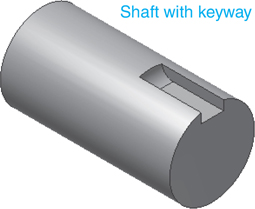
Figure 10-38
Pratt and Whitney Keys
Pratt and Whitney keys are similar to square keys but have rounded ends. See Figure 10-25.
A key similar to a square key but with rounded ends.
Exercise 10-7 Drawing a Shaft with a Pratt and Whitney Keyway
![]() Start a new drawing using the Standard (mm).iam format.
Start a new drawing using the Standard (mm).iam format.
![]() Click the Design tab and select the Shaft option.
Click the Design tab and select the Shaft option.
![]() Draw a Ø30 × 65 shaft with 3 × 45° chamfers at each end; click OK.
Draw a Ø30 × 65 shaft with 3 × 45° chamfers at each end; click OK.
See Figure 10-39.
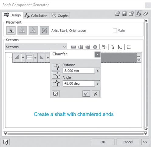
Figure 10-39
![]() Select the Add Keyway groove located under the Select Features tool.
Select the Add Keyway groove located under the Select Features tool.
See Figure 10-40. A default preview of a keyway will appear.

Figure 10-40
![]() Click the Feature Properties box on the keyway callout line.
Click the Feature Properties box on the keyway callout line.
The Keyway dialog box will appear. See Figure 10-41.
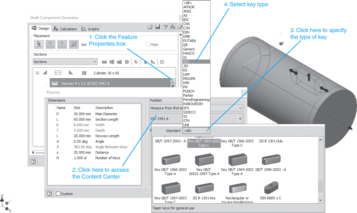
Figure 10-41
![]() Access the Content Center and select an ISO 2491 A key.
Access the Content Center and select an ISO 2491 A key.
See Figure 10-42.

Figure 10-42
![]() Return to the Keyway dialog box; click OK.
Return to the Keyway dialog box; click OK.
See Figure 10-43.

Figure 10-43
The grayed numbers cannot be changed; they were generated when the ISO 2491 A key was selected. The values in black can be changed.
![]() Change the distance value to 18; click OK.
Change the distance value to 18; click OK.
Figure 10-44 shows the finished keyway.
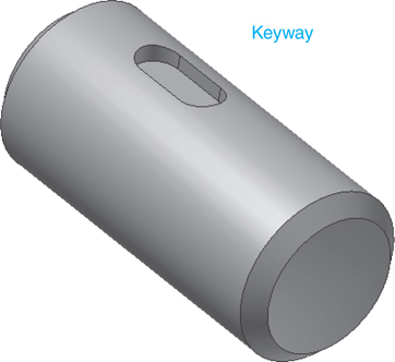
Figure 10-44
![]() Access the Place from Content Center dialog box and add the key.
Access the Place from Content Center dialog box and add the key.
See Figure 10-45.
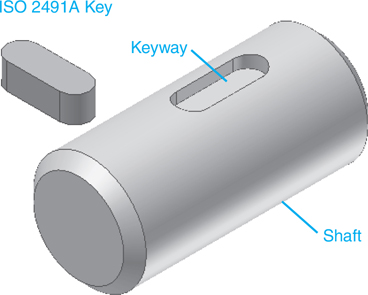
Figure 10-45
![]() Use the Constrain tool and place the key into the keyway.
Use the Constrain tool and place the key into the keyway.
See Figure 10-46.

Figure 10-46
Figure 10-47 shows the shaft and key mounted into a hub.

Figure 10-47
Exercise 10-8 Drawing a Pratt and Whitney Keyway Using the Key Option on the Power Transmission Panel Located under the Design Tab
![]() Start a new drawing using the Standard (mm).iam format.
Start a new drawing using the Standard (mm).iam format.
![]() Access the Shaft tool located on the Power Transmission panel.
Access the Shaft tool located on the Power Transmission panel.
![]() Draw a Ø30× 65 shaft.
Draw a Ø30× 65 shaft.
See Figure 10-48.

Figure 10-48
![]() Click the Key tool on the Power Transmission panel under the Design tab.
Click the Key tool on the Power Transmission panel under the Design tab.
See Figure 10-49. The Parallel Key Connection Generator box will appear. See Figure 10-50.

Figure 10-49
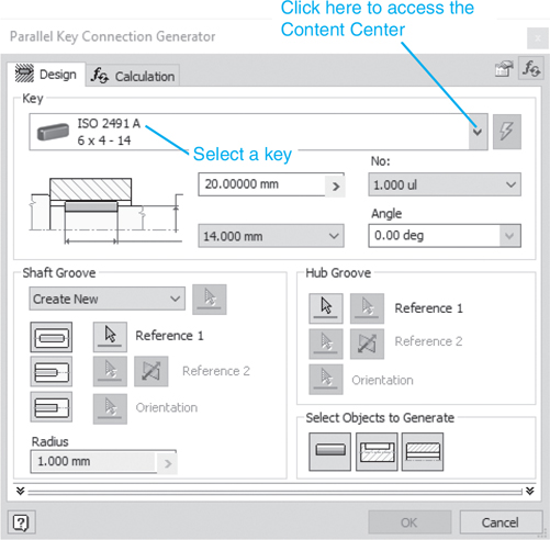
Figure 10-50
![]() Access the Content Center by clicking the arrowhead as shown, and select a key.
Access the Content Center by clicking the arrowhead as shown, and select a key.
![]() Click the Groove with Rounded Edges box, then click the rounded side of the shaft. After the Groove with Rounded Edges box is clicked, the Reference 1 box will activate automatically, followed by the Reference 2 box.
Click the Groove with Rounded Edges box, then click the rounded side of the shaft. After the Groove with Rounded Edges box is clicked, the Reference 1 box will activate automatically, followed by the Reference 2 box.
See Figure 10-51.

Figure 10-51
The Planar Face of Work Plane box will automatically be highlighted. A preview of the keyway will appear on the shaft. See Figure 10-52. The arrows on the preview can be used to control the position, length, and orientation of the keyway.
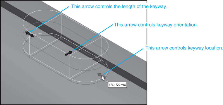
Figure 10-52
![]() Edit the keyway as needed, click the Insert Key box, click the Insert Hub Groove box, then click OK.
Edit the keyway as needed, click the Insert Key box, click the Insert Hub Groove box, then click OK.
Figure 10-53 shows the finished keyway.

Figure 10-53
Exercise 10-9 Creating a Plain Groove Keyway at the End of a Shaft
Plain grooves are used with square keys.
![]() Start a new drawing using the Standard (mm).iam format.
Start a new drawing using the Standard (mm).iam format.
![]() Click the Shaft tool located on the Power Transmission panel under the Design tab.
Click the Shaft tool located on the Power Transmission panel under the Design tab.
![]() Draw a Ø30 × 65 shaft.
Draw a Ø30 × 65 shaft.
![]() Access the Key tool on the Power Transmission panel.
Access the Key tool on the Power Transmission panel.
![]() Select a key.
Select a key.
In this example, a DIN 6885 B key was selected.
![]() Click the Plain Groove box.
Click the Plain Groove box.
See Figure 10-54.
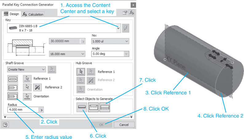
Figure 10-54
![]() Click the Reference 1 box, and click the rounded side of the shaft.
Click the Reference 1 box, and click the rounded side of the shaft.
The Reference 2 box will automatically be highlighted.
![]() Click the end of the shaft, click the Insert Key box, click the Insert Hub Groove box, then click OK.
Click the end of the shaft, click the Insert Key box, click the Insert Hub Groove box, then click OK.
Figure 10-55 shows the resulting plain groove.
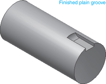
Figure 10-55
Woodruff Keys
Woodruff keys are crescent shape. The crescent shape allows for some slight rotation between the shaft and hub.
A crescent-shape key that allows for some slight rotation between the shaft and hub.
Exercise 10-10 Drawing a Shaft with a Woodruff Key
![]() Create a new drawing using the Standard (mm).iam format.
Create a new drawing using the Standard (mm).iam format.
![]() Access the Place from Content Center tool, click Shaft Parts, click Keys, then click Keys - Woodruff.
Access the Place from Content Center tool, click Shaft Parts, click Keys, then click Keys - Woodruff.
See Figure 10-56.
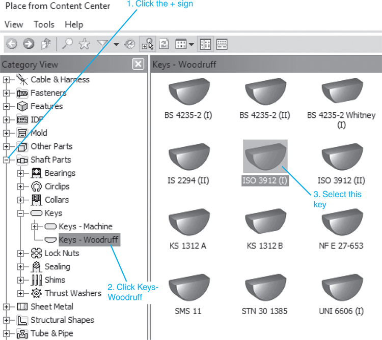
Figure 10-56
![]() Select an ISO 3912 (I) key and select the 32–38 shaft diameter option.
Select an ISO 3912 (I) key and select the 32–38 shaft diameter option.
See Figure 10-57. Click the Table View tab. The dimensions listed will be used to create the shaft keyway.
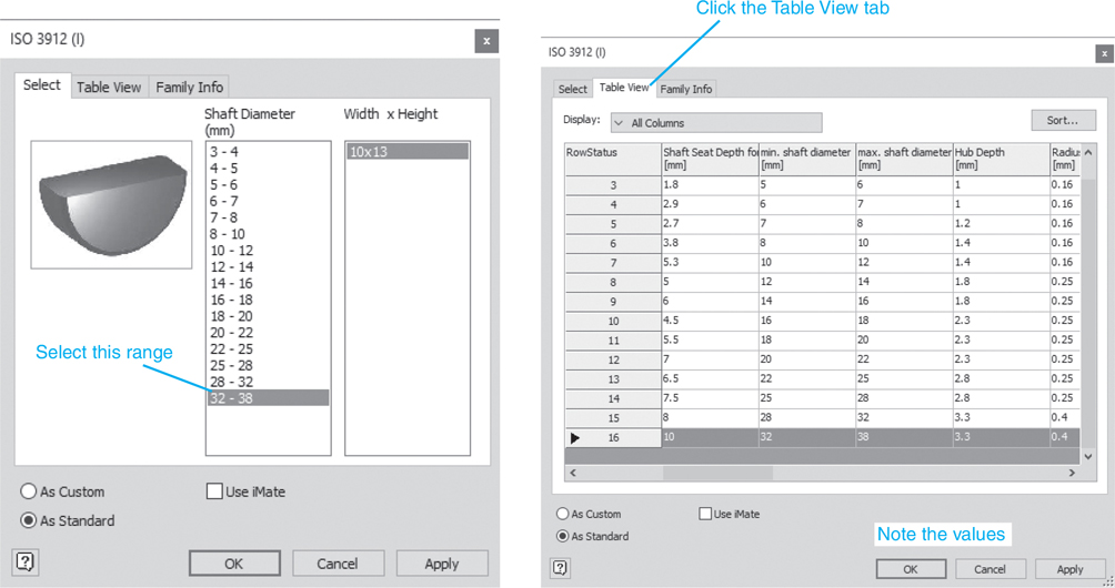
Figure 10-57
![]() Click Apply.
Click Apply.
The key will appear on the screen. We must determine the size of the key to create an appropriate keyway in the shaft. Refer to the table values in Figure 10-57. The Woodruff key diameter is 32, and the shaft seat depth is 10. The key itself has a height of 13.
Note
The depth of the keyway is 10, and the key diameter is 32.
![]() Access the Shaft tool on the Power Transmission panel and draw a Ø32 × 65 shaft. Create an offset YZ work plane through the center of the shaft and create a new sketch plane on the work plane.
Access the Shaft tool on the Power Transmission panel and draw a Ø32 × 65 shaft. Create an offset YZ work plane through the center of the shaft and create a new sketch plane on the work plane.
See Figure 10-58. The shaft has a diameter of 32, so the work plane will be offset 16 from the edge of the shaft.

Figure 10-58
![]() Rotate the shaft into a 2D view and add lines and a circle as shown in Figure 10-59.
Rotate the shaft into a 2D view and add lines and a circle as shown in Figure 10-59.
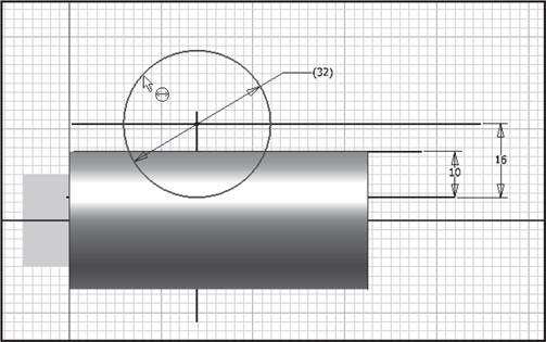
Figure 10-59
The dimensions used came from the Table View values for the key.
![]() Return to an isometric view and select the Extrude tool. Use the Cut and Intersection options to create a cylinder from the circle drawn in step 6.
Return to an isometric view and select the Extrude tool. Use the Cut and Intersection options to create a cylinder from the circle drawn in step 6.
See Figures 10-60 and 10-61.
Figure 10-60

Figure 10-61
![]() Use the Constrain tool to locate the key into the shaft’s keyway.
Use the Constrain tool to locate the key into the shaft’s keyway.
See Figure 10-62.
Figure 10-62
Tip
You may have to use work planes to locate the key into the shaft.
Figure 10-63 shows a hub design to fit over the shaft and Woodruff key shown in Figure 10-62. The 19.3 dimension value was derived from adding the bore hole radius of 16.0 to a hub depth value of 3.3 listed in the Table View for the key.

Figure 10-63
Shafts with Splines
Splines are a series of cutouts in a shaft that are sized to match a corresponding set of cutouts in a hub. Splines are used to transmit torque.
A series of cutouts in a shaft that are sized to match a corresponding set of cutouts in a hub; used to transmit torque.
Tip
Splines are generally used on larger shafts. Smaller shafts use setscrews or pins.
Exercise 10-11 Drawing a Spline
![]() Create a new drawing using the Standard (mm).iam format.
Create a new drawing using the Standard (mm).iam format.
![]() Use the Shaft tool on the Power Transmission panel under the Design tab to create a Ø32× 65 shaft.
Use the Shaft tool on the Power Transmission panel under the Design tab to create a Ø32× 65 shaft.
See Figure 10-64.

Figure 10-64
Note
The shaft could have been drawn directly on the .iam drawing using the Create Component tool.
![]() Click the Parallel Splines tool on the Power Transmission panel under the Design tab.
Click the Parallel Splines tool on the Power Transmission panel under the Design tab.
See Figure 10-65.
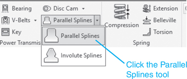
Figure 10-65
The Parallel Splines Connection Generator dialog box will appear.
See Figure 10-66.
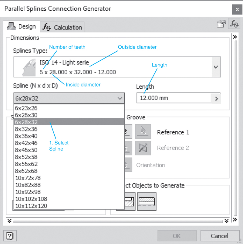
Figure 10-66
Note
The sequence of clicks used to create a spline is critical.
![]() Set the Splines Type for light, the Spline (N× d× D) dimensions for 6× 28× 32, the spline Length for 12, and the Radius for 4.
Set the Splines Type for light, the Spline (N× d× D) dimensions for 6× 28× 32, the spline Length for 12, and the Radius for 4.
See Figure 10-67.

Figure 10-67
Tip
The outside diameter of the spline must equal the outside diameter of the shaft.
![]() Click the Reference 1 box, click the rounded sides of the shaft (the Reference 2 box will automatically become active), click the flat end of the shaft, click the right-hand box in the Select Objects to Generate box, then click OK.
Click the Reference 1 box, click the rounded sides of the shaft (the Reference 2 box will automatically become active), click the flat end of the shaft, click the right-hand box in the Select Objects to Generate box, then click OK.
The File Naming dialog box will appear.
![]() Click OK.
Click OK.
Figure 10-68 shows the finished spline.

Figure 10-68
Retain the Ø32 × 65 shaft with the splined end and continue to work on the same assembly drawing for the next exercise. A Ø90 × 10 hub will be added to the assembly. A spline will be cut into the hub and inserted onto the Ø32 shaft.
Tip
Splines are defined by the dimensions N×d×D, where N is the number of teeth on the spline, d is the inside diameter, and D is the outside diameter.
Exercise 10-12 Drawing a Hub
![]() Click the Shaft tool on the Power Transmission panel and create a Ø90× 10 shaft.
Click the Shaft tool on the Power Transmission panel and create a Ø90× 10 shaft.
See Figures 10-69 and 10-70. The new shaft will be listed in the browser box as Shaft:2.
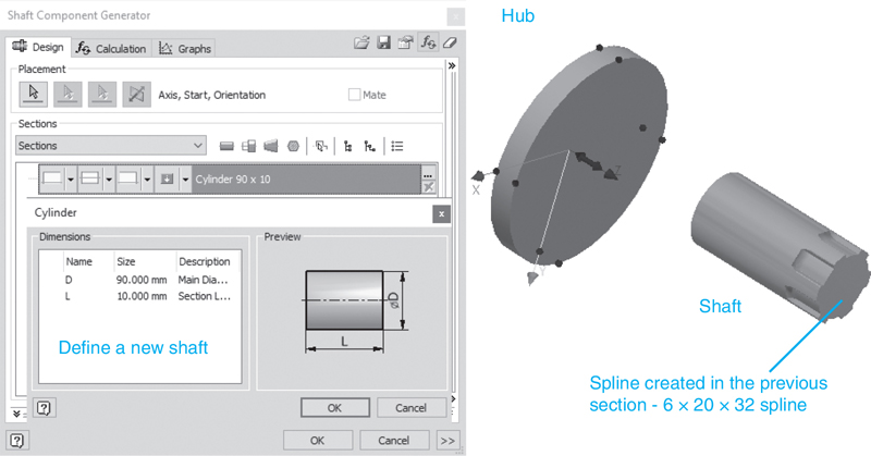
Figure 10-69

Figure 10-70
![]() Click the Shaft:2 heading in the browser box and select the Open option.
Click the Shaft:2 heading in the browser box and select the Open option.
See Figure 10-71.

Figure 10-71
![]() Right-click the hub (Shaft:2) and select the Open option.
Right-click the hub (Shaft:2) and select the Open option.
See Figure 10-72.
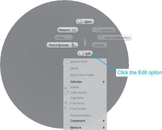
Figure 10-72
Tip
The hole diameter must equal the inside diameter of the spline.
![]() Right-click the front surface of the Ø90 × 10 shaft and create a new sketch plane on the front surface of the hub as shown and add a Point, Center Point at the origin of the shaft.
Right-click the front surface of the Ø90 × 10 shaft and create a new sketch plane on the front surface of the hub as shown and add a Point, Center Point at the origin of the shaft.
See Figure 10-73.
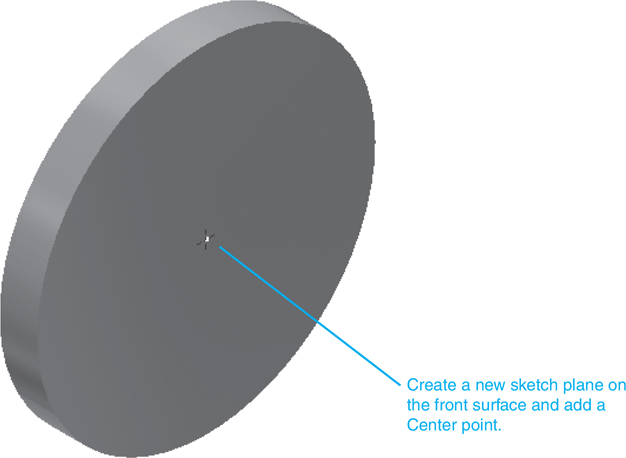
Figure 10-73
![]() Right-click and select Finish 2D Sketch.
Right-click and select Finish 2D Sketch.
See Figure 10-74.
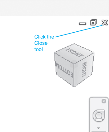
Figure 10-74
![]() Access the Hole tool on the Modify panel and create a Ø28 hole through the Ø90 shaft (hub).
Access the Hole tool on the Modify panel and create a Ø28 hole through the Ø90 shaft (hub).
![]() Right-click the mouse and select the Finish Edit option.
Right-click the mouse and select the Finish Edit option.
![]() Click the X box in the upper right corner of the Shaft drawing screen.
Click the X box in the upper right corner of the Shaft drawing screen.
A warning box will appear.
![]() Click the Yes box.
Click the Yes box.
The Save dialog box will appear.
![]() Click OK.
Click OK.
The drawing screen will return to the assembly screen showing both the Ø32 shaft and the Ø90 hub.
![]() Click the hub.
Click the hub.
The Ø32 hole will appear in the hub. See Figure 10-75.

Figure 10-75
![]() Click the Parallel Splines tool on the Power Transmission panel.
Click the Parallel Splines tool on the Power Transmission panel.
![]() Select an ISO - 14 Light series spline with dimensions of 6× 28.000× 32.0002 12.000.
Select an ISO - 14 Light series spline with dimensions of 6× 28.000× 32.0002 12.000.
![]() Click the Reference 1 box in the Hub Groove box, click the surface of the hub, click the Reference 2 box, click the edge of the Ø28 hole, click the left box in the Select Objects to Generate box, then click OK.
Click the Reference 1 box in the Hub Groove box, click the surface of the hub, click the Reference 2 box, click the edge of the Ø28 hole, click the left box in the Select Objects to Generate box, then click OK.
The File Naming dialog box will appear.
![]() Click OK.
Click OK.
Figure 10-76 shows the hub with a splined hole.
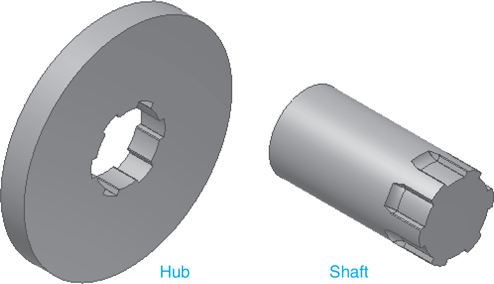
Figure 10-76
![]() Return to the Assemble panel bar and use the Insert tool on the Constrain panel and mount the hub onto the shaft.
Return to the Assemble panel bar and use the Insert tool on the Constrain panel and mount the hub onto the shaft.
See Figure 10-77.

Figure 10-77
Collars
Collars are used to hold shafts in position as they rotate. Collars may be mounted inside or outside the support structure. See Figure 10-78.
Used to hold a shaft in place as it rotates; may be mounted on the inside or outside of the support structure.
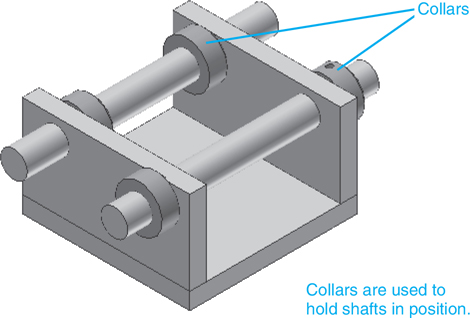
Figure 10-78
Exercise 10-13 Adding Collars to a Shaft Assembly—Setscrews
![]() Start a new drawing using the Standard (mm).iam format.
Start a new drawing using the Standard (mm).iam format.
![]() Click the Place from Content Center tool, click Shaft Parts, then Collars.
Click the Place from Content Center tool, click Shaft Parts, then Collars.
See Figure 10-79. In this example, a DIN 705 B collar with a Ø16 was selected.

Figure 10-79
![]() Click the DIN 705 B icon, and click OK.
Click the DIN 705 B icon, and click OK.
The DIN 705 B dialog box will appear.
![]() Select an Inside Diameter of 16 and click the Table View tab, then All Columns.
Select an Inside Diameter of 16 and click the Table View tab, then All Columns.
See Figure 10-80. Note the size specifications for the collar. In this example the Nominal Diameter is the diameter of the small hole in the collar. The diameter of the hole is 4.

Figure 10-80
This hole can be threaded and a setscrew added to hold the collar on the shaft.
See Exercise 3-15 for instructions on how to create an offset work plane. Once a work plane is established, a new sketch may be created and used to create a threaded hole.
![]() Access the Place from Content Center dialog box and select a setscrew. Setscrews are located under Fasteners, Bolts, and Setscrews. See Exercise 6-21 for information about setscrews.
Access the Place from Content Center dialog box and select a setscrew. Setscrews are located under Fasteners, Bolts, and Setscrews. See Exercise 6-21 for information about setscrews.
See Figure 10-81. In this example a DIN EN 27434 Set Screw with an M4 thread, a 6 length, and a conical point was selected.

Figure 10-81
![]() Use the Constrain tool and insert the setscrew into the hole.
Use the Constrain tool and insert the setscrew into the hole.
The assembly sequence presented here is one of several possibilities.
![]() Insert the setscrew into the drawing and position it above the hole.
Insert the setscrew into the drawing and position it above the hole.
See Figure 10-81.
![]() Draw a work axis through the hole and use the Mate tool on the Constrain panel to align the hole’s work axis with the setscrew’s axis.
Draw a work axis through the hole and use the Mate tool on the Constrain panel to align the hole’s work axis with the setscrew’s axis.
![]() Draw a work plane tangent to the collar and hole’s edge. Use the Flush tool on the Constrain panel to make the setscrew flush with the work plane.
Draw a work plane tangent to the collar and hole’s edge. Use the Flush tool on the Constrain panel to make the setscrew flush with the work plane.
![]() Hide the work plane and work axis.
Hide the work plane and work axis.
Adding Collars to a Shaft Assembly—Pins
A collar may be held in place using pins. Figure 10-82 shows a shaft and a DIN 705 B collar, both with Ø4.00 holes. A pin will be inserted through the hole in the collar into the hole in the shaft.
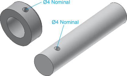
Figure 10-82
Figure 10-83 shows some of the different types of pins available in the Inventor Content Center. For this example a spring-type cylindrical pin will be used. These type pins are squeezed to a smaller diameter, inserted into the hole, and then released back to their original diameter.

Figure 10-83
![]() Insert the collar onto the shaft with the holes aligned.
Insert the collar onto the shaft with the holes aligned.
See Figure 10-84.

Figure 10-84
Note
Consider defining a work axis through the holes to help with the alignment.
![]() Click the Place from Content Center tool, and select the Fasteners, Pins, and Cylindrical options.
Click the Place from Content Center tool, and select the Fasteners, Pins, and Cylindrical options.
See Figures 10-85 and 10-86. In this example, a DIN EN ISO 13337 spring-type pin with a Nominal Diameter of 4 and a Nominal Length of 20 was selected. The length 20 was selected because the collar thickness is 6, and the shaft diameter is 16, for a total of 22. There is only one hole in the collar, so the pin length cannot exceed 22 or it will extend beyond the collar. A length value of 20 allows for a clearance of 2. Figure 10-87 shows the selected pin with the collar and shaft.
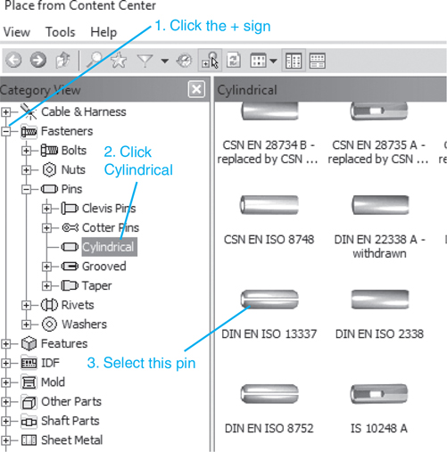
Figure 10-85
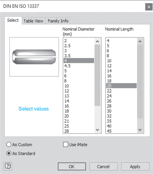
Figure 10-86

Figure 10-87
Note
Consider using work planes and a work axis when constraining the pin and collar.
![]() Use the Constrain tool to assemble the pin into the collar and shaft.
Use the Constrain tool to assemble the pin into the collar and shaft.
See Figure 10-88.
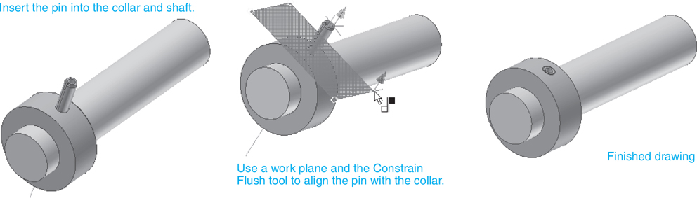
Figure 10-88
O-Rings
O-rings are used to create seals. The rings are forced between two different objects, which distorts the rings and creates a seal.
a ring forced between two objects to create a seal.
Exercise 10-14 Drawing an O-Ring and a Shaft
Assume the nominal diameter of the shaft is 0.500.
![]() Create a new drawing using the Standard (in).iam format.
Create a new drawing using the Standard (in).iam format.
![]() Click the Design tab and use the Shaft tool on the Power Transmission panel to draw a Ø0.500× 2.50 shaft.
Click the Design tab and use the Shaft tool on the Power Transmission panel to draw a Ø0.500× 2.50 shaft.
![]() Click the Assemble tab and use the Place from Content Center dialog box to click Shaft Parts, Sealing, O-Rings, and select an AS 568 O-Ring.
Click the Assemble tab and use the Place from Content Center dialog box to click Shaft Parts, Sealing, O-Rings, and select an AS 568 O-Ring.
See Figure 10-89.
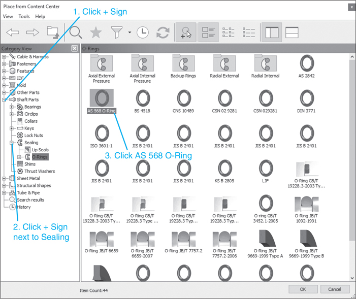
Figure 10-89
![]() Click the Table View tab, then All Columns. Select a DASH # 014 O-Ring because it has a 0.489 inside diameter.
Click the Table View tab, then All Columns. Select a DASH # 014 O-Ring because it has a 0.489 inside diameter.
See Figure 10-90.

Figure 10-90
Note
The cross section for this O-ring is 0.07.
![]() Insert the ring into the drawing.
Insert the ring into the drawing.
![]() Right-click the Shaft:1 heading in the browser box and select the Edit using Design Accelerator option.
Right-click the Shaft:1 heading in the browser box and select the Edit using Design Accelerator option.
See Figure 10-91. The Shaft Component Generator dialog box will appear.
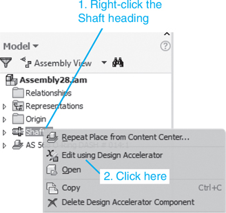
Figure 10-91
See Figure 10-92.
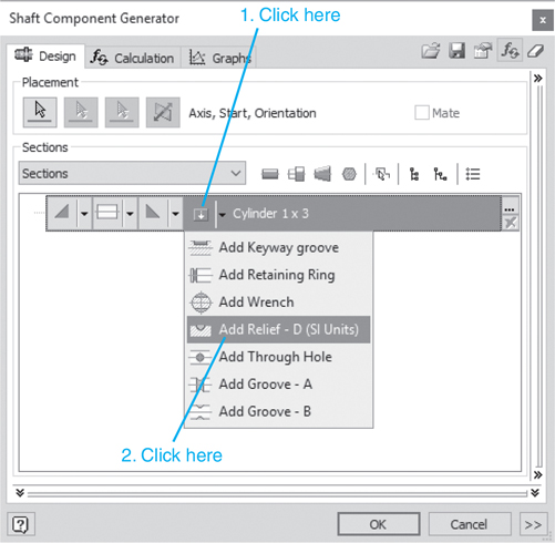
Figure 10-92
![]() Select the Add Relief - D (SI Units) option.
Select the Add Relief - D (SI Units) option.
The Relief - D option will appear on the screen.
See Figure 10-93.
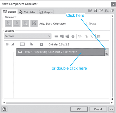
Figure 10-93
![]() Click the Element Properties box.
Click the Element Properties box.
The Relief - D (SI Units) dialog box will appear. See Figure 10-94.

Figure 10-94
![]() Enter the distance from the second edge. Click the Custom box and enter the values as shown in Figure 10-94. (These values were derived from the Content Center.) Unclick the Custom box. Click OK.
Enter the distance from the second edge. Click the Custom box and enter the values as shown in Figure 10-94. (These values were derived from the Content Center.) Unclick the Custom box. Click OK.
The Shaft Component Generator dialog box will appear.
![]() Click OK.
Click OK.
Figure 10-95 shows the O-ring and modified shaft.
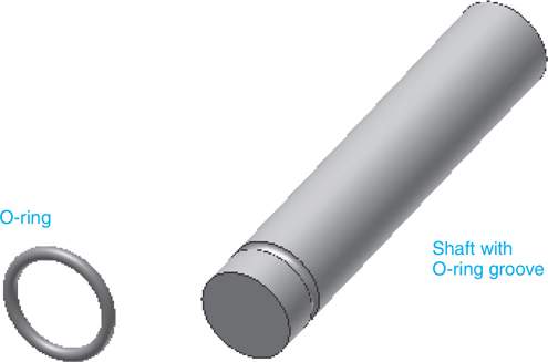
Figure 10-95
![]() Use the Constrain tool to position the O-ring onto the shaft’s groove.
Use the Constrain tool to position the O-ring onto the shaft’s groove.
The procedure presented here is one possibility.
![]() Draw an XY work plane through the O-ring.
Draw an XY work plane through the O-ring.
See Figure 10-96.


Figure 10-96
![]() Use the Mate tool on the Constrain panel and align the X axis of the O-ring with the X axis of the shaft.
Use the Mate tool on the Constrain panel and align the X axis of the O-ring with the X axis of the shaft.
![]() Use the Flush tool to align the front surface of the shaft with the work plane on the O-ring, then define a −0.25 offset.
Use the Flush tool to align the front surface of the shaft with the work plane on the O-ring, then define a −0.25 offset.
Figure 10-96 shows the finished O-ring and shaft.
Drawing Shafts and Pins Using the Tools Under the Design Tab
Pins can also be drawn using the tools located under the Design tab. Figure 10-97 shows a hub with a 20 inside diameter, a 40 outside diameter, a thickness of 16, and a through hole of Ø6. A work plane has been created tangent to the hub. Figure 10-97 also shows a Ø20 × 30 shaft with a Ø6 hole and a 1 × 45° chamfer at each end. The shaft was created using the Shaft tool located on the Power Transmission panel under the Design tab. The hub and the shaft are to be assembled together and held together using a pin. The drawing was created using the Standard (mm).iam format.
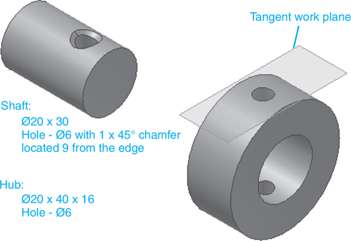
Figure 10-97
Exercise 10-15 Drawing a Pin Using the Design Tab
![]() Click the Design tab, click the arrowhead on the Clevis Pin icon and select the Radial Pin tool. The Radial Pin Component Generator dialog box will appear.
Click the Design tab, click the arrowhead on the Clevis Pin icon and select the Radial Pin tool. The Radial Pin Component Generator dialog box will appear.
See Figure 10-98.
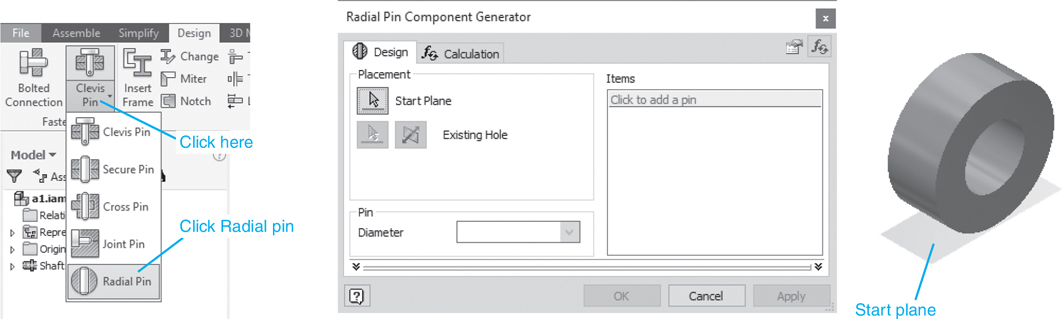
Figure 10-98
![]() Select the Start Plane box, then the work plane on the hub. Select the Existing Hole box, then the Ø6 hole on the hub. Click the Click to add a pin box to access the Content Center.
Select the Start Plane box, then the work plane on the hub. Select the Existing Hole box, then the Ø6 hole on the hub. Click the Click to add a pin box to access the Content Center.
See Figure 10-99.

Figure 10-99
![]() In the Place from Content Center dialog box, select the Cylindrical pin option and a DIN EN ISO 8752 pin. Select a Ø6 × 40 pin.
In the Place from Content Center dialog box, select the Cylindrical pin option and a DIN EN ISO 8752 pin. Select a Ø6 × 40 pin.
See Figures 10-100 and 10-101. Figures 10-102 and 10-103 show the pin in the assembly drawing.
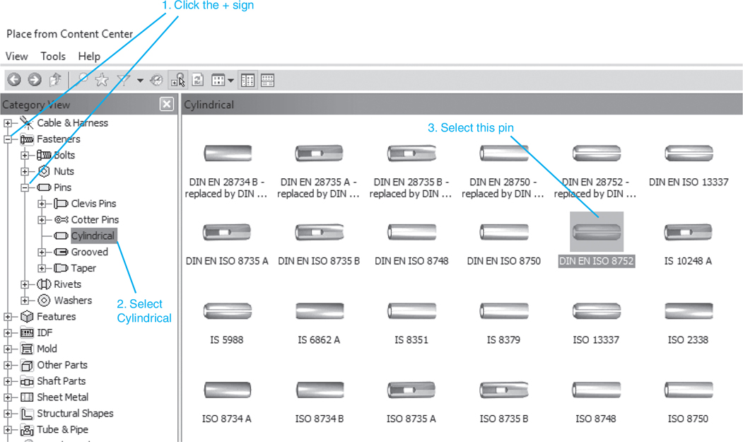
Figure 10-100

Figure 10-101
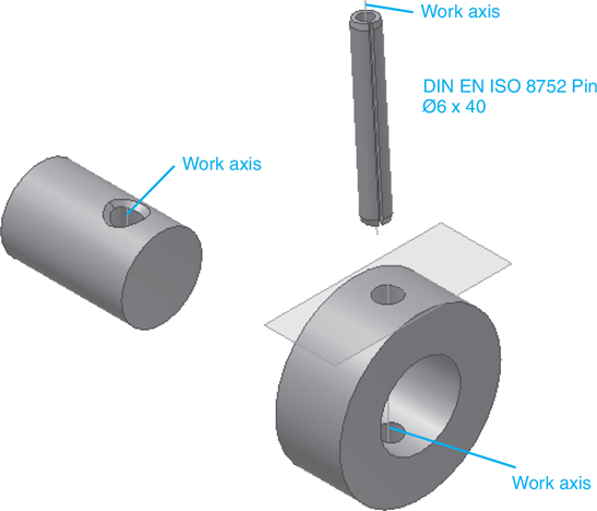
Figure 10-102

Figure 10-103
Tip
Create work axes for each of the three parts to help align the assembly.
![]() Use the Constrain tool and assemble the parts.
Use the Constrain tool and assemble the parts.
Figure 10-103 shows the finished assembly.
Chapter Summary
This chapter illustrated how to use the tools located under the Design tab to draw shafts, how to add retaining ring grooves to shafts, how to add keyways to shafts, how to add O-ring grooves to shafts, how to add pin holes to shafts, and how to use the Content Center to add retaining rings, keys, O-rings, and pins to shafts. The five general types of keys were described and illustrated, namely, Pratt and Whitney, square, rectangular, Woodruff, and Gib.
Splines on a shaft for transmitting torque were also introduced and used in a drawing.
Chapter Test Questions
Multiple Choice
Circle the correct answer.
1. Which of the following is not a type of key?
a. Pratt and Whitney
b. Square
c. Russell
d. Woodruff
2. Which term best describes the shape of a Woodruff key?
a. Round
b. Rectangular
c. Square
d. Crescent
3. Which of the following is not a type of pin?
a. Round
b. Cotter
c. Taper
d. Clevis
4. The dimensions needed to define a groove in a shaft for a retaining ring are found in the
a. Design tab panel tools
b. Content Center
c. Drawing Annotation panel
5. Which type of key is crescent shape?
a. Pratt and Whitney
b. Woodruff
c. Rounded
d. Machine
6. What is a slot cut through a hub sized to accept a key called?
a. Keyslot
b. Hubslot
c. Keyway
d. Slot
7. Spring pins are fitted into holes by
a. Squeezing them to a smaller diameter, inserting them into a hole, then releasing them back to original size
b. Fitting them with compression springs that are released once the pins are inserted into a hole
c. Press fitting them into a hole with spring pressure
8. Threaded holes in collars are usually fitted with
a. Spring pins
b. Setscrews
c. Rivets
d. Cotter pins
9. Splines are used to transfer which type of forces?
a. Linear
b. Rotary
c. Impact
d. Compression
10. When a shaft is a simple cylinder, the ends are said to have
a. Chamfers
b. Fillets
c. No features
d. Orthographic ends
Matching
Match the key and pin names with their pictures. See Figures 10-104 and 10-105.

Figure 10-104

Figure 10-105
1. Woodruff __________ |
7. Cylindrical spring type ________ |
2. Pratt and Whitney __________ |
8. Clevis __________ |
3. Rectangular __________ |
9. Cylindrical __________ |
4. Gib __________ |
10. Taper __________ |
5. Square __________ |
11. Grooved __________ |
6. Cotter __________ |
True or False
Circle the correct answer.
1. True or False: Chamfers can be added to shafts using Design tab panel tools.
2. True or False: Shafts must always have chamfers on their ends.
3. True or False: Retaining rings are used to prevent longitudinal movement of shafts.
4. True or False: Retaining rings can be either external or internal.
5. True or False: Keys are used with shafts to transfer rotary motion and torque.
6. True or False: Pratt and Whitney keys have rounded ends.
7. True or False: Woodruff keys are rectangular.
8. True or False: Splines are a series of cutouts in a shaft that are sized to match a corresponding set of cutouts in a hub.
9. True or False: Collars are used to hold shafts in position as they rotate.
10. True or False: O-rings are used to create seals.
Chapter Projects
Draw the following uniform shafts.
Project 10-1: Inches
See Figure P10-1.

Figure P10-1
Ø.50 × 3.50
0.10 × 45° chamfer, both ends
Project 10-2: Inches
See Figure P10-2.
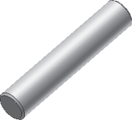
Figure P10-2
Ø2.00 × 10.00
0.125 × 45° chamfer, both ends
Project 10-3: Millimeters
See Figure P10-3.
Figure P10-3
Ø20 × 110
3 × 45° chamfer, both ends
Project 10-4: Millimeters
See Figure P10-4.

Figure P10-4
Ø60 × 100
5 × 45° chamfer, both ends
Draw the following shafts and retaining rings. Create the appropriate grooves on the shaft, and position the retaining rings onto the shaft.
Project 10-5: Inches
See Figure P10-5.
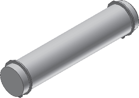
Figure P10-5
Draw a Ø1.00 × 5.00 shaft.
Mount two BS 3673: Part 1 Inch retaining rings located 0.25 from each end.
Draw a 0.06 × 45° chamfer on each end.
Project 10-6: Inches
See Figure P10-6.
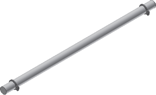
Figure P10-6
Draw a Ø.25 × 6.00 shaft.
Mount two BS 3673: Part 1 Inch retaining rings located 0.375 from each end.
Draw a 0.03 × 45° chamfer on each end.
Project 10-7: Millimeters
See Figure P10-7.
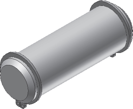
Figure P10-7
Draw a Ø20 × 50 shaft.
Mount two CSN 02 2930 Metric retaining rings located 2 from each end.
Draw a 3 × 45° chamfer on each end.
Project 10-8: Millimeters
See Figure P10-8.
Figure P10-8A
Draw a Ø16 × 64 shaft.
Mount two CSN 02 2930 Metric retaining rings located 10 from each end.
Draw a 4 × 45° chamfer on each end.
Draw the shafts and keys in Figure P10-8B.
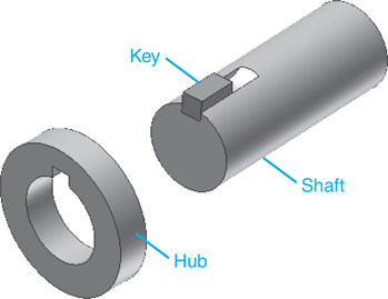
Figure P10-8B
Project 10-9: Inches
Draw a Ø2.00 × 5.25 shaft with 0.125 × 45° chamfers at each end. Draw a keyway on one end on the shaft to match the size requirements of a square key (see the Content Center) that is 1/2 × 1/2 × 1.25 long and has a nominal diameter range of 1.75–2.25. Insert the key into the shaft’s keyway. Draw a hub with an inside diameter of 2.00, an outside diameter of 3.50, and a thickness of 0.75. Add the appropriate keyway to the hub, then insert the hub over the shaft and key.
Project 10-10: Inches
Draw a Ø3.50 × 10.00 shaft with 0.25 × 45° chamfers at each end. Draw a keyway on one end on the shaft to match the size requirements of a square key (see the Content Center) that is 7/8 × 7/8 × 2.50 long and has a nominal diameter range of 3.25–3.75. Insert the key into the shaft’s keyway. Draw a hub with an inside diameter of 3.50, an outside diameter of 5.00, and a thickness of 1.00. Add the appropriate keyway to the hub, then insert the hub over the shaft and key.
Project 10-11: Millimeters
Draw a Ø26 × 72 shaft with 3 × 45° chamfers at each end. Draw a keyway on one end on the shaft to match the size requirements of an IS 2048 B key (see the Content Center) that is 2 × 2 × 22 long and has a nominal diameter range of 22–30. Insert the key into the shaft’s keyway. Draw a hub with an inside diameter of 26, an outside diameter of 40, and a thickness of 14. Add the appropriate keyway to the hub, then insert the hub over the shaft and key.
Project 10-12: Millimeters
Draw a Ø60 × 240 shaft with 5 × 45° chamfers at each end. Draw a keyway on one end on the shaft to match the size requirements of an IS 2048 B key (see the Content Center) that is 18 × 11 × 70 long and has a nominal diameter range of 58–65. Insert the key into the shaft’s keyway. Draw a hub with an inside diameter of 60, an outside diameter of 80, and a thickness of 20. Add the appropriate keyway to the hub, then insert the hub over the shaft and key. Draw the shafts and keys in Figure P10-12.

Figure P10-12
Project 10-13: Millimeters
Draw a Ø20 × 65 shaft with 3 × 45° chamfers at each end. Draw a keyway on the shaft to match the size requirements of a DIN 6885 A key (see the Content Center). Locate the shaft’s keyway 24 from the end of the shaft. Insert the key into the shaft’s keyway. Draw a hub with an inside diameter of 20, an outside diameter of 35, and a thickness of 10. Add the appropriate keyway to the hub, then insert the hub over the shaft and key.
Project 10-14: Millimeters
Draw a Ø52 × 100 shaft with 6 × 45° chamfers at each end. Draw a keyway on the shaft to match the size requirements of a DIN 6885 A key (see the Content Center). Locate the shaft’s keyway 34 from the edge of the shaft. Insert the key into the shaft’s keyway. Draw a hub with an inside diameter of 52, an outside diameter of 70, and a thickness of 16. Add the appropriate keyway to the hub, then insert the hub over the shaft and key.
Project 10-15: Inches
Draw a Ø0.750 × 4.25 shaft with 0.125 × 45° chamfers at each end. Draw a keyway 0.500 from the end of the shaft to match the size requirements of a 0.1875 × 0.1875 × 0.74 rectangular or square parallel key that has a nominal diameter range of 0.57–0.88 (see the Content Center). Insert the key into the shaft’s keyway. Draw a hub with an inside diameter of 0.75, an outside diameter of 2.50, and a thickness of 0.625. Add the appropriate keyway to the hub, then insert the hub over the shaft and key.
Project 10-16: Inches
Draw a Ø1.50 × 7.50 shaft with 0.19 × 45° chamfers at each end. Draw a keyway 2.50 from the end of the shaft to match the size requirements of a 0.375 × 0.375 × 0.875 rectangular or square parallel key that has a nominal diameter range of 1.38–1.75. Insert the key into the shaft’s keyway. Draw a hub with an inside diameter of 1.50, an outside diameter of 2.75, and a thickness of 0.750. Add the appropriate keyway to the hub, then insert the hub over the shaft and key.
Project 10-17: Millimeters
Draw a Ø163 × 40 shaft with 2 × 45° chamfers at each end. Draw a keyway 10 from the end of the shaft to match the size requirements of a CSN 30 1385 Woodruff key. Insert the key into the shaft’s keyway. Draw a hub with an inside diameter of 16, an outside diameter of 40, and a thickness of 8. Add the appropriate keyway to the hub, then insert the hub over the shaft and key.
Project 10-18: Millimeters
Draw a Ø40 × 105 shaft with 4 × 45° chamfers at each end. Draw a keyway 27 from the end of the shaft to match the size requirements of a CSN 30 1385 Woodruff key. Insert the key into the shaft’s keyway. Draw a hub with an inside diameter of 40, an outside diameter of 75, and a thickness of 12. Add the appropriate keyway to the hub, then insert the hub over the shaft and key.
Project 10-19: Inches
Draw a Ø0.750 × 4.25 shaft with 0.125 × 45° chamfers at each end. Draw a keyway 0.500 from the end of the shaft to match the size requirements of a Full Radius No. 606 3/16 × 0.75 Woodruff key (see the Content Center). Insert the key into the shaft’s keyway. Draw a hub with an inside diameter of 0.75, an outside diameter of 2.50, and a thickness of 0.625. Add the appropriate keyway to the hub, then insert the hub over the shaft and key.
Project 10-20: Inches
Draw a Ø1.50 × 7.50 shaft with 0.19 × 45° chamfers at each end. Draw a keyway 2.50 from the end of the shaft to match the size requirements of a Full Radius No. 1422 I 7/16 × 2 Woodruff key (see the Content Center). Insert the key into the shaft’s keyway. Draw a hub with an inside diameter of 1.50, an outside diameter of 2.75, and a thickness of 0.750. Add the appropriate keyway to the hub, then insert the hub over the shaft and key.
Draw the shafts and hubs in Figures P10-20A through P10-20D.
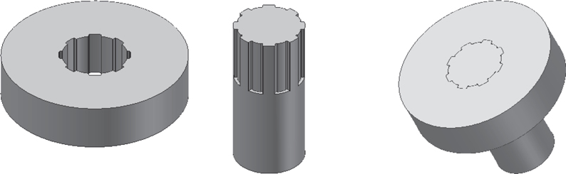
Figure P10-20A

Figure P10-20B
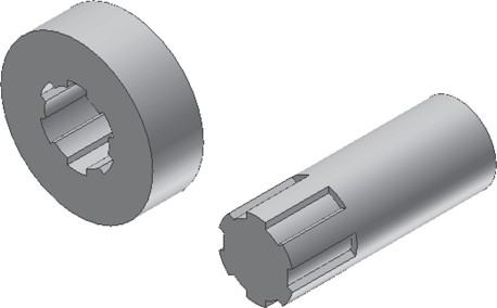
Figure P10-20C
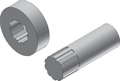
Figure P10-20D
Project 10-21: Millimeters
Draw a shaft and hub based on the following data and join them using a spline:
Shaft: Ø120 × 30
Spline Type = Light
Spline Dimensions = 8 × 42 × 46
Active Spline Length = 38
Hub: Ø46 × 100
Project 10-22: Millimeters
Draw a shaft and hub based on the following data and join them using a spline:
Shaft: Ø78 × 200
Spline Type = Light
Spline Dimensions = 10 × 72 × 78
Active Spline Length = 60
Hub: Ø160 × 40
Project 10-23: Inches
Draw a shaft and hub based on the following data and join them using a spline:
Shaft: Ø1.50 × 4
Fit Type = 6B To Side − No Load
Nominal Diameter = 1.50
Active Spline Length = 1.25
Hub: Ø3 × 1
Project 10-24: Inches
Draw a shaft and hub based on the following data and join them using a spline:
Shaft: Ø2 × 6
Fit Type = 10 A Permanent Fit
Nominal Diameter = 2
Active Spline Length = 1.75
Hub: Ø4.5 × 1.25
Project 10-25: Millimeters
Create a 3D drawing of the Shaft Support Assembly in Figure P10-25 for each of the following sets of parameters. Also include an exploded isometric drawing with assembly numbers and a parts list.

Figure P10-25A
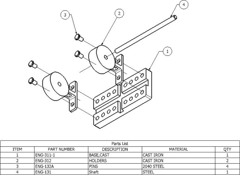
Figure P10-25B
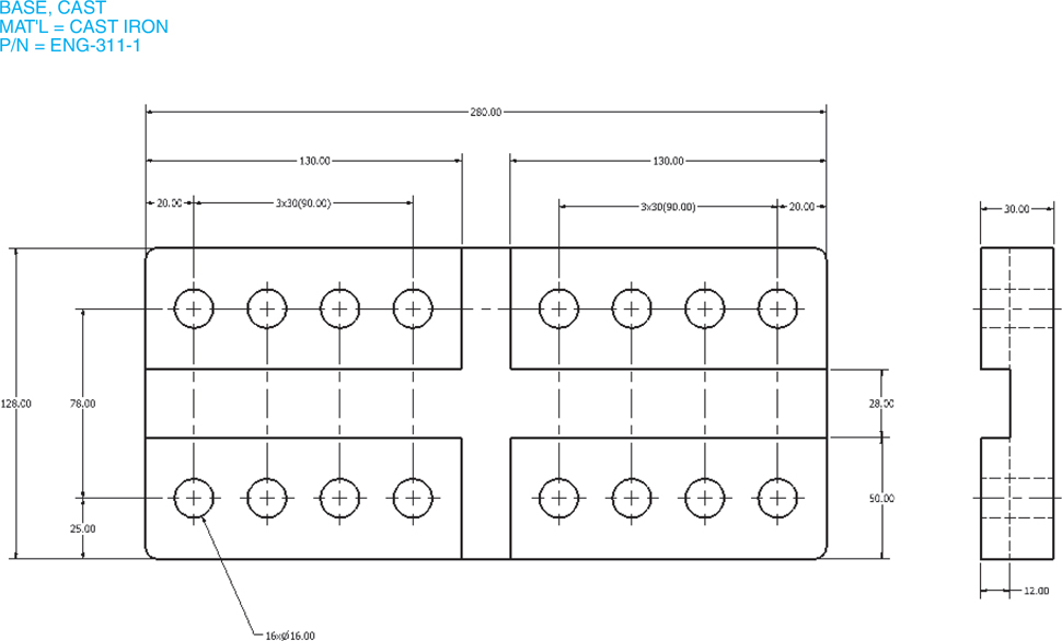
Figure P10-25C

Figure P10-25D

Figure P10-25E
A straight uniform shaft, Ø16 × 320 with 2 × 45° chamfers at each end. The shaft is to protrude 20 from the face of the holders.
A straight uniform shaft, Ø16 × 320 with 2 × 45° chamfers at each end. The shaft is to protrude 20 from the face of the holders. Add the appropriate grooves and insert two CNS 9074 external retaining rings located 17 from each end of the shaft.
A straight uniform shaft, Ø16 × 320 with 2 × 45° chamfers at each end. The shaft is to protrude 20 from the face of the holders. Add the appropriate grooves and insert two E-ring - Type - 3CM external retaining rings located 18 from each end of the shaft.
A straight uniform shaft, Ø16 × 320 with 2 × 45° chamfers at each end. The shaft is to protrude 20 from the face of the holders. Add two CNS - 122 collars with Ø4 set screws.
A straight uniform shaft, Ø16 × 320 with 2 × 45° chamfers at each end. The shaft is to protrude 20 from the face of the support. Add two CNS - 122 collars with Ø4 spring-type straight pins.
A straight uniform shaft, Ø16 × 280 with 2 × 45° chamfers at each end. On one end, insert a square key between the shaft and the holders.
A straight uniform shaft, Ø16 × 320 with 2 × 45° chamfers at each end. On one end, insert a UNI 7510A key between the shaft and the support. The shaft is to protrude 20 from the surface of the holders.
A straight uniform shaft, Ø16 × 320 with 2 × 45° chamfers at each end. On one end, insert a JIS B 1302 - Type B Woodruff key between the shaft and the support. The shaft is to protrude 20 from the surface of the holders.
Project 10-26: Inches
Create the drawings of the Adjustable Assembly shown in Figures P10-26A through P10-26F.
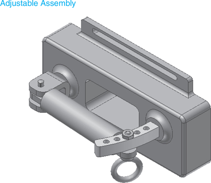
Figure P10-26A

Figure P10-26B

Figure P10-26C

Figure P10-26D
Figure P10-26E

Figure P10-26F
The grooved pin was created using the tools under the Design tab. The forged eyebolt, hex machine screw nut, and hex nut were created using the Content Center.
A 3D assembly drawing
An exploded 3D assembly drawing
An exploded isometric drawing with assembly numbers
A parts list