Chapter Fourteen. Weldment Drawings
Chapter Objectives
Understand how to design and draw weldments
Learn about fillet and groove welds
Learn how to create weld symbols
Introduction
Weldments are assemblies made from several smaller parts that have been welded together. Weldments are often less expensive to manufacture because they save extensive machining time or replace expensive castings.
An assembly made from several smaller parts that have been welded together.
Fillet Welds
Figure 14-1 shows a simple weldment. It was created from two 0.375-in. thick plates and joined by a fillet weld. The base plate is 2.00 × 4.00 in., and the vertical plate is 1.25 × 4.00 in. Both parts are made from low-carbon steel.
A weld usually created at 45° to join pieces that are perpendicular to each other; may be continuous or intermittent.

Figure 14-1
Exercise 14-1 Creating the Components
![]() Click the New tool, then the English tab, Weldment (ANSI).iam, and Create.
Click the New tool, then the English tab, Weldment (ANSI).iam, and Create.
![]() Click the Assemble tab and click the Create tool located on the Component panel.
Click the Assemble tab and click the Create tool located on the Component panel.
The Create In-Place Component dialog box will appear. See Figure 14-2.
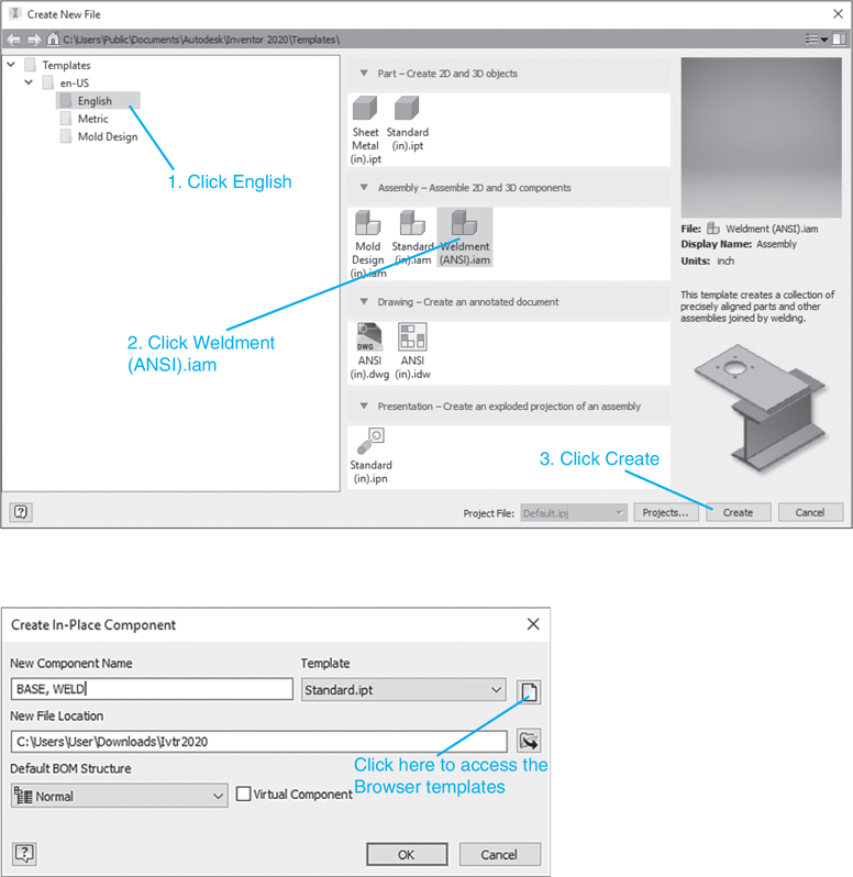
Figure 14-2
![]() Define a new component named BASE,WELD.
Define a new component named BASE,WELD.
![]() Click the Browse Templates box.
Click the Browse Templates box.
The Open Template dialog box will appear. See Figure 14-3.
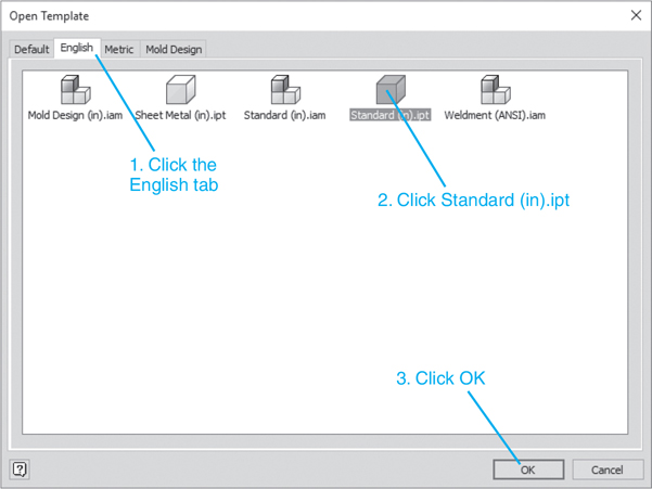
Figure 14-3
![]() Select the Standard (in).ipt format. Click OK.
Select the Standard (in).ipt format. Click OK.
The Create In-Place Component dialog box will reappear. Note that EnglishStandard (in).ipt is the new template. See Figure 14-4.

Figure 14-4
![]() Click OK.
Click OK.
A small icon will appear next to the cursor.
![]() Click the drawing screen.
Click the drawing screen.
The Sketch tab tools will appear.
![]() Click the Start 2D Sketch tool, select the XY plane, and sketch a 2.00× 4.00 rectangle.
Click the Start 2D Sketch tool, select the XY plane, and sketch a 2.00× 4.00 rectangle.
![]() Right-click the mouse and click Finish 2D Sketch.
Right-click the mouse and click Finish 2D Sketch.
The 3D Model tab tools will appear.
![]() Click the Extrude tool and define a thickness of 0.375 for the rectangle.
Click the Extrude tool and define a thickness of 0.375 for the rectangle.
See Figure 14-5.
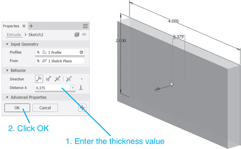
Figure 14-5
Exercise 14-2 Creating a Second Plate
![]() Right-click the mouse and select the Finish Edit option.
Right-click the mouse and select the Finish Edit option.
See Figure 14-6.

Figure 14-6
![]() Select the Copy tool. The Copy tool is located on the Pattern panel under the Assemble tab.
Select the Copy tool. The Copy tool is located on the Pattern panel under the Assemble tab.
See Figure 14-7. The Copy Components: Status dialog box will appear.
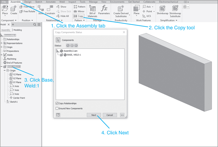
Figure 14-7
![]() Click the BASE, WELD:1 component.
Click the BASE, WELD:1 component.
The component file name will appear in the dialog box.
![]() Click Next.
Click Next.
The Copy Components: File Names dialog box will appear. See Figure 14-8.
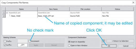
Figure 14-8
The copied component will be assigned a new file name. In this example, the new name is BASE, WELD_CPY.ipt. Another name may be entered.
![]() Click the Increment box and remove the check mark. Click the OK box.
Click the Increment box and remove the check mark. Click the OK box.
The component copy will appear on the screen. See Figure 14-9.
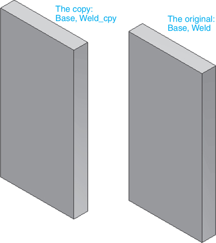
Figure 14-9
Exercise 14-3 Creating a T-Bracket
![]() Right-click BASE, WELD_CPY: in the browser box and click the Grounded option.
Right-click BASE, WELD_CPY: in the browser box and click the Grounded option.
See Figure 14-10. This will remove the grounded constraint. The pushpin icon will disappear from the browser box.
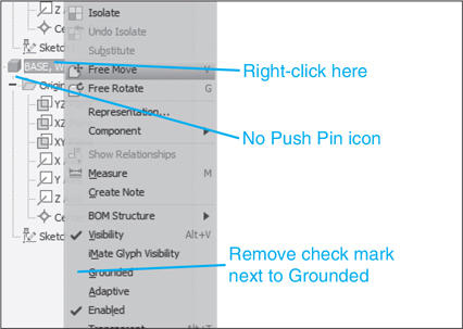
Figure 14-10
![]() Use the Free Rotate and Constrain tools and assemble the two plates to form a T-bracket. Change the orientation as desired.
Use the Free Rotate and Constrain tools and assemble the two plates to form a T-bracket. Change the orientation as desired.
See Figure 14-11.

Figure 14-11
![]() Right-click the mouse and select the Finish Edit option.
Right-click the mouse and select the Finish Edit option.
Exercise 14-4 Creating the Welds
![]() Click the Welds tool on the Process panel under the Weld tab.
Click the Welds tool on the Process panel under the Weld tab.
See Figure 14-12. The Weld panel tools will appear. (The Weld panel can also be accessed by double-clicking the Welds heading in the Browser box.)
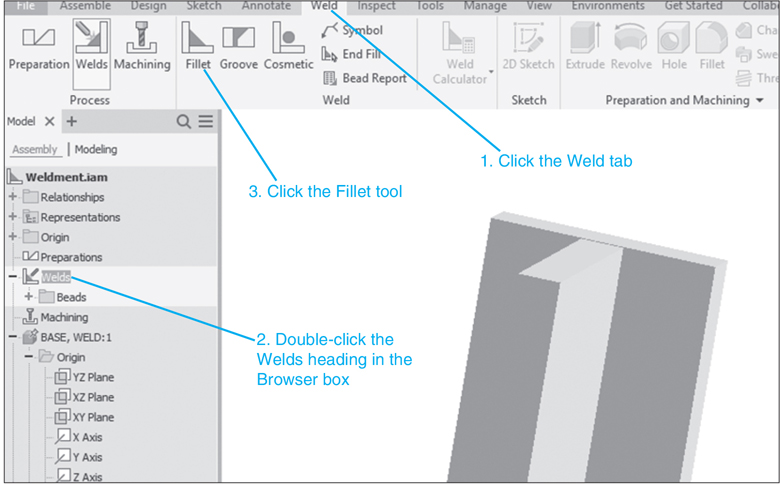
Figure 14-12
![]() Click the Fillet tool on the Weld panel under the Weld tab.
Click the Fillet tool on the Weld panel under the Weld tab.
The Fillet Weld dialog box will appear. See Figure 14-13.

Figure 14-13
![]() Set the weld size to 0.125, as shown.
Set the weld size to 0.125, as shown.
![]() Click the 1 box, then click the front vertical surface of the part BASE, WELD.
Click the 1 box, then click the front vertical surface of the part BASE, WELD.
![]() Click the 2 box, then click the right vertical surface of the part BASE, WELD_CPY.
Click the 2 box, then click the right vertical surface of the part BASE, WELD_CPY.
A preview of the weld will appear as small right triangles. See Figure 14-13.
![]() Click OK.
Click OK.
Figure 14-14 shows the finished weld.
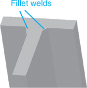
Figure 14-14
Intermittent Fillet Welds
Fillet welds may be located intermittently along a weld line.
![]() Rotate the T-bracket created in the previous section so that the side opposite the fillet weld is expanded.
Rotate the T-bracket created in the previous section so that the side opposite the fillet weld is expanded.
![]() Click the Fillet tool on the Weld panel.
Click the Fillet tool on the Weld panel.
The Fillet Weld dialog box will appear. See Figure 14-15.

Figure 14-15
![]() Enter the appropriate Intermittency values.
Enter the appropriate Intermittency values.
Note that the values 1.00 and 1.50 have been entered in the Intermittency box. The 1.00 value is the length of each weld, and the 1.50 value is the distance from the center of one weld to the center of the next.
![]() Define surfaces 1 and 2 as before.
Define surfaces 1 and 2 as before.
![]() Click Apply.
Click Apply.
Figure 14-16 shows the finished intermittent welds.
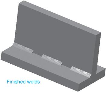
Figure 14-16
Weld Symbols
Welds are defined on drawings using symbols. The symbol for a fillet weld is shown in Figure 14-17. Note that the location of the flag-like portion of the symbol defines the location of the weld. It is not always possible to point directly at a weld location, so the Other side symbol is very useful.

Figure 14-17
The size of the weld is defined as shown. Most fillet welds are created at 45°, although other angles are possible. A fillet weld defined by .25 indicates that the 45° weld is defined by two sides, both .25 long. Metric values are used to define a weld size in the same manner.
Exercise 14-5 Adding a Weld Symbol to a Drawing
This example will use the T-bracket shown in Figure 14-11.
![]() Start a new drawing using English units and the Weldment (ANSI).iam format.
Start a new drawing using English units and the Weldment (ANSI).iam format.
![]() Click the Assemble tab, select the Place Component tool on the Component panel, and locate the T-bracket on the drawing screen.
Click the Assemble tab, select the Place Component tool on the Component panel, and locate the T-bracket on the drawing screen.
![]() Rotate the T-bracket so that the portion of the bracket that does not have a weld is visible.
Rotate the T-bracket so that the portion of the bracket that does not have a weld is visible.
See Figure 14-18.
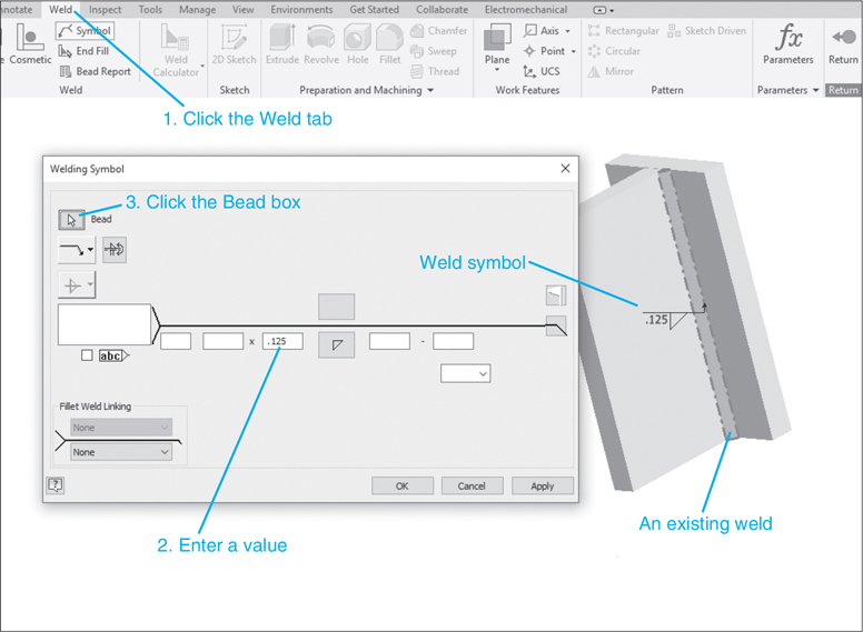
Figure 14-18
![]() Click the Weld tool, click the Fillet tool, and add a .125 fillet weld; click OK.
Click the Weld tool, click the Fillet tool, and add a .125 fillet weld; click OK.
![]() Click the Symbol tool located on the Weld panel.
Click the Symbol tool located on the Weld panel.
The Welding Symbol dialog box will appear. See Figure 14-18.
![]() Enter the .125 value, click the Bead box.
Enter the .125 value, click the Bead box.
The weld symbol will appear.
![]() Click OK.
Click OK.
Figure 14-19 shows a weld drawing with a weld symbol. The weldment has been reoriented to better show the weld symbol.
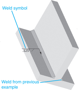
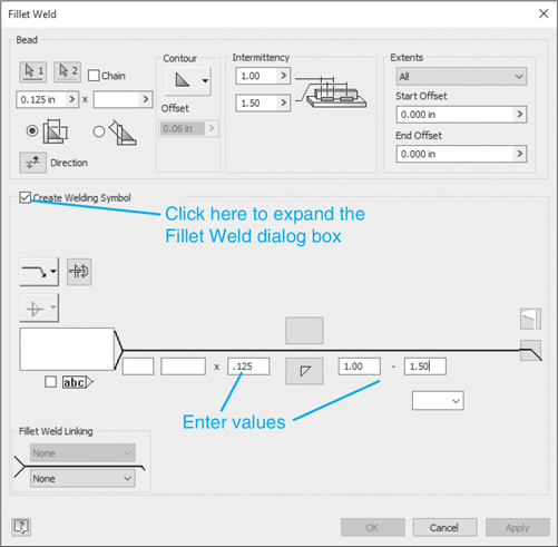
Figure 14-19
Note
The fillet weld and symbol can be created together by first clicking the Create Welding Symbol box on the Fillet Weld dialog box. When the box is clicked the Fillet Weld dialog box will expand to include welding symbols.
Figure 14-20 shows the fillet weld symbol for an intermittent fillet weld. It was created using the same procedure as for the continuous weld.

Figure 14-20
All Around
The addition of a circle to the fillet weld symbol indicates that the weld is to be placed all around the object. Figure 14-21 shows a cylinder welded to a plate. In this example, the fillet weld was defined using millimeters. A 5-mm × 5-mm weld is to be created all the way around the cylinder.

Figure 14-21
Exercise 14-6 Creating an All-Around Fillet Weld
![]() Start a new drawing, click the Metric tab, and create a new drawing using the Weldment (ANSI-mm).iam format.
Start a new drawing, click the Metric tab, and create a new drawing using the Weldment (ANSI-mm).iam format.
![]() Create a 5× 40× 40-mm plate and a Ø20× 30 cylinder.
Create a 5× 40× 40-mm plate and a Ø20× 30 cylinder.
![]() Assemble the parts so that the cylinder is centered on the plate.
Assemble the parts so that the cylinder is centered on the plate.
![]() Click Welds in the browser box, then click the Fillet Weld tool on the Weld panel.
Click Welds in the browser box, then click the Fillet Weld tool on the Weld panel.
The Fillet Weld dialog box will appear. See Figure 14-21.
![]() Set the weld size for 5 mm, then click the Create Welding Symbol box.
Set the weld size for 5 mm, then click the Create Welding Symbol box.
![]() Enter a fillet weld value of 5.
Enter a fillet weld value of 5.
![]() Click the box at the right end of the horizontal segment of the symbol arrow, where the arrow symbol changes direction, to create a circle around the bend in the arrow.
Click the box at the right end of the horizontal segment of the symbol arrow, where the arrow symbol changes direction, to create a circle around the bend in the arrow.
![]() Click OK.
Click OK.
Figure 14-22 shows the finished weld and symbol.
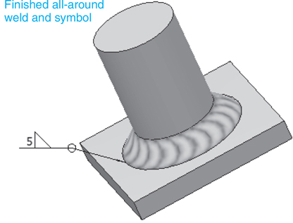
Figure 14-22
Weldments—Groove Welds
Groove welds are used when two parts abut. A chamfer is cut into each part and the weld is placed in the resulting groove. Figure 14-23 shows an L-bracket created as a weldment.
A weld used when two parts abut, placed in the groove formed when a chamfer is cut into each part.

Figure 14-23
It was created as follows:
![]() Draw a .375× 2.00× 4.00-in. plate and cut a .19× .19 chamfer as shown.
Draw a .375× 2.00× 4.00-in. plate and cut a .19× .19 chamfer as shown.
![]() Create a weldment drawing using the Weldment (ANSI).iam format.
Create a weldment drawing using the Weldment (ANSI).iam format.
![]() Click the Assemble tab, click the Place Component tool located on the Component panel, and add the two plates to the drawing. Use the Constrain tool and assemble the plates as shown.
Click the Assemble tab, click the Place Component tool located on the Component panel, and add the two plates to the drawing. Use the Constrain tool and assemble the plates as shown.
![]() Click the Weld tab, click the Welds tool, and click the Groove Weld tool on the Weld panel.
Click the Weld tab, click the Welds tool, and click the Groove Weld tool on the Weld panel.
The Groove Weld dialog box will appear.
![]() Click the Full Face Weld boxes for both Face Set 1 and Face Set 2.
Click the Full Face Weld boxes for both Face Set 1 and Face Set 2.
![]() Define Face 1 and Face 2 as shown, and click OK.
Define Face 1 and Face 2 as shown, and click OK.
Sample Problem SP14-1
Figure 14-24 shows an object that is to be manufactured as a weldment created from three parts: the barrel, the center plate, and the front plate.

Figure 14-24
Exercise 14-7 Creating the Weldment
Use the Weldment (ISO).iam format. The dimensions for each part were derived from those given in Figure 14-24.
![]() Start a new drawing, click the Metric tab, and use the Weldment (ISO).iam format.
Start a new drawing, click the Metric tab, and use the Weldment (ISO).iam format.
![]() Use the Create tool (use the Standard (mm).ipt format) and create a 15× 55× 110 plate with a 5× 5 chamfer and a Ø15 and Ø16 holes as shown.
Use the Create tool (use the Standard (mm).ipt format) and create a 15× 55× 110 plate with a 5× 5 chamfer and a Ø15 and Ø16 holes as shown.
![]() Right-click and select the Finish Edit option.
Right-click and select the Finish Edit option.
![]() Use the Create tool and create a Ø46× 35 barrel with a Ø16 through-all hole. Use the Constrain tool to position the barrel.
Use the Create tool and create a Ø46× 35 barrel with a Ø16 through-all hole. Use the Constrain tool to position the barrel.
![]() Reorient the model and use the Create tool to create a 20× 55× 35 flange with a 25× 20 cutout as shown.
Reorient the model and use the Create tool to create a 20× 55× 35 flange with a 25× 20 cutout as shown.
![]() Add a groove weld as shown.
Add a groove weld as shown.
![]() Add a 5× 5 fillet weld as shown.
Add a 5× 5 fillet weld as shown.
![]() Add a 2× 2 fillet weld around the barrel as shown.
Add a 2× 2 fillet weld around the barrel as shown.
Figure 14-25 shows the weldment.
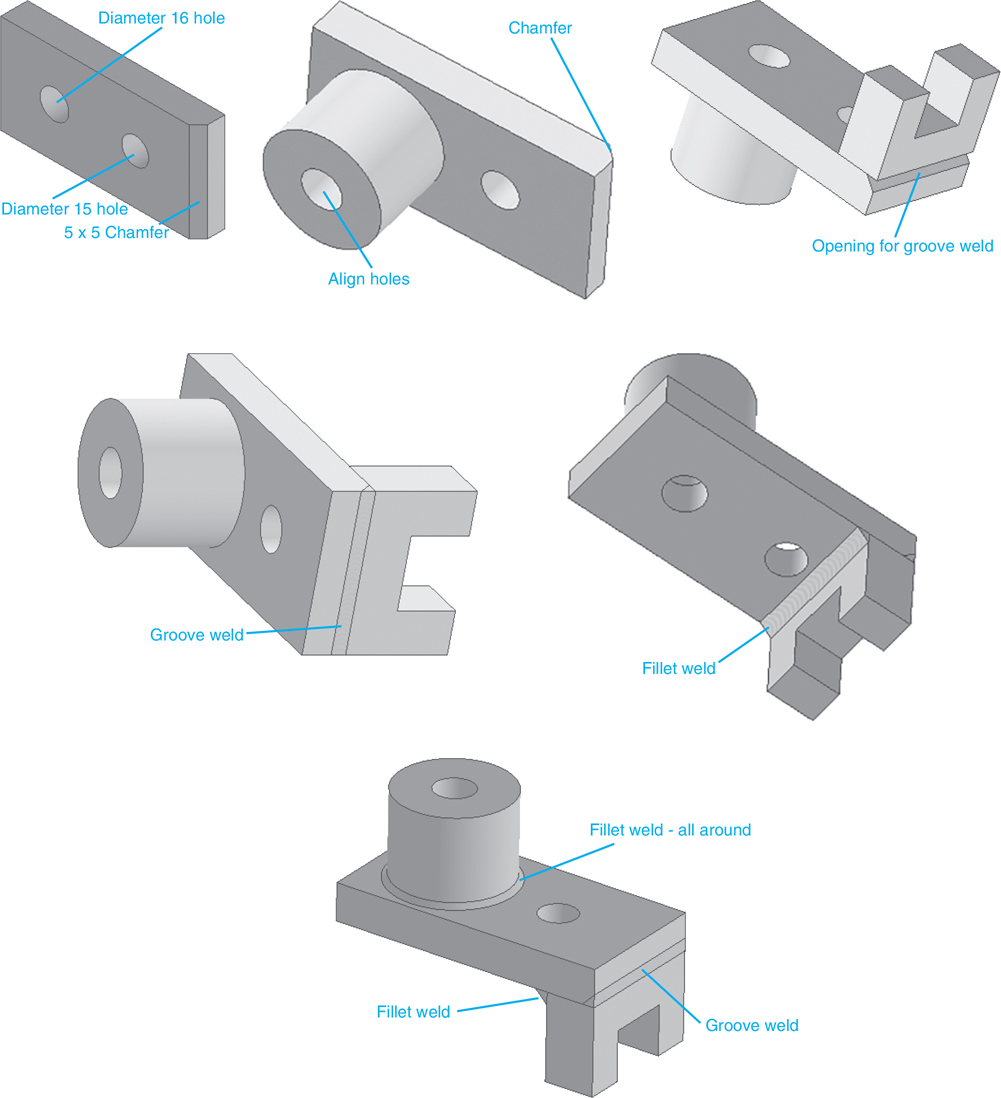
Figure 14-25
Chapter Summary
This chapter illustrated how to create and draw weldments, which are assemblies of several parts welded together. Fillet welds, both continuous and intermittent as well as all around, were introduced; welding symbols were added to drawings; and groove welds were illustrated.
Chapter Test Questions
Multiple Choice
Circle the correct answer.
1. What shape is the symbol for a fillet weld?
a. Circle
b. Flag-like
c. Square
d. Hexagon
2. A circle added to the fillet weld symbol means
a. Weld all around
b. Use a round weld bead
c. Use a cosmetic weld
3. Groove welds are generally associated with
a. Fillets
b. Holes
c. Chamfers
d. Cutouts
4. The weld tools are accessed by clicking the Welds tool located in the
a. Weldment Assembly Panel
b. Standard toolbar
c. Tools pull-down menu
d. Browser
5. A weld symbol that has a symbol both above and below the horizontal segment of the symbol indicates
a. Weld the other side
b. Weld both sides
c. Weld all around
d. Weld the closest side
True or False
Circle the correct answer.
1. True or False: A weldment is an assembly made from several smaller parts that have been welded together.
2. True or False: Inventor can draw both continuous and intermittent welds.
3. True or False: The symbol for a fillet weld is a circle.
4. True or False: A groove weld is used when two parts abut.
5. True or False: Fillet welds can be defined in two ways: by two edge distances or the distance from front to back.
Chapter Project
Project 14-1
For Figures P14-1 through P14-10, redesign the given parts as weldments. Use either 5-mm or .20-in. fillet welds.
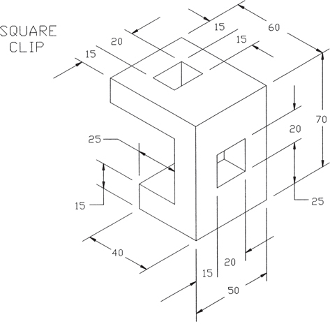
Figure P14-1 MILLIMETERS
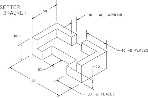
Figure P14-2 MILLIMETERS
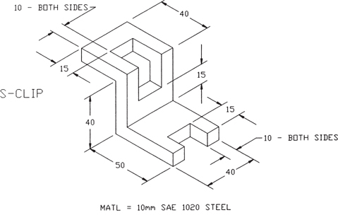
Figure P14-3 MILLIMETERS
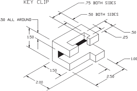
Figure P14-4 INCHES
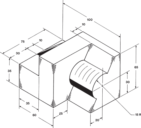
Figure P14-5 MILLIMETERS
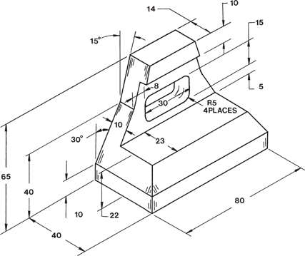
Figure P14-6 MILLIMETERS

Figure P14-7 MILLIMETERS

Figure P14-8 MILLIMETERS
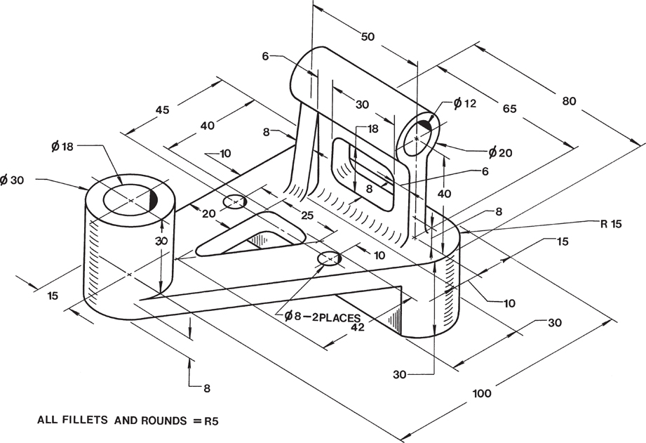
Figure P14-9 MILLIMETERS
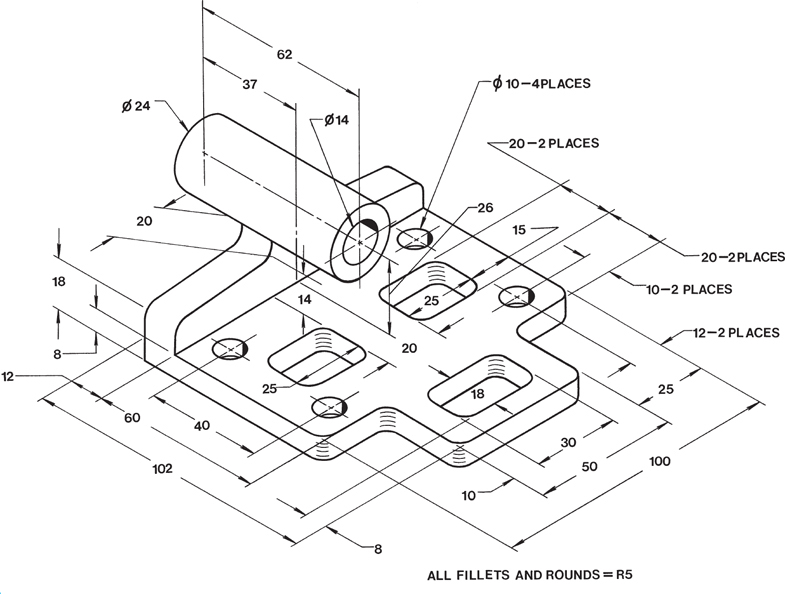
Figure P14-10 MILLIMETERS