Chapter Fifteen. Cams
Chapter Objectives
Learn how to use the Disc Cam tool located on the Power Transmission panel under the Design tab
Learn how to create and use displacement diagrams
Learn how to insert cams into assembly drawings
Introduction
This chapter explains how to draw and design cams. Cams are eccentric objects that convert rotary motion into linear motion. Cams are fitted onto rotating shafts, and lift and lower followers as they rotate.
An eccentric object that converts rotary motion into linear motion.
Cams can be designed and drawn using the Disc Cam tool. Displacement diagrams are defined and cams are generated from the displacement diagrams. The shape of the cam’s profile causes the follower to rise and fall as the cam rotates. Changes in the cam’s displacement cause the follower to accelerate. Excessive acceleration can generate excessive forces.
Figure 15-1 shows a cam drawn using Inventor. The cam bore includes a keyway.

Figure 15-1
Displacement Diagrams
Displacement diagrams are used to define the motion of a cam using a linear diagram. The distances are then transferred to a base circle to create the required cam shape. Inventor will automatically create a cam from given displacement information.
A linear diagram used to define the motion of a cam.
Figure 15-2 shows a displacement diagram and a cam shape generated from the information on the diagram. The displacement diagram shown is drawn using only straight lines, which is called uniform motion. This diagram results in points of discontinuity that can result in erratic follower motion. Several different shapes can be used to smooth out these areas and create smoother follower motion.
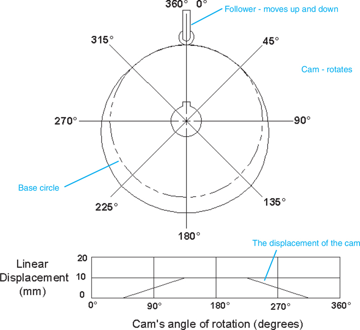
Figure 15-2
Drawing a Cam Using Inventor
A cam is drawn using the Disc Cam tool by first defining the physical characteristics of the cam then defining the cam’s displacement diagram. A drawing of the cam will then automatically be generated.
Exercise 15-1 Drawing a Cam
![]() Start a new drawing, click the Metric tab, and use the Standard (mm).iam format.
Start a new drawing, click the Metric tab, and use the Standard (mm).iam format.
![]() Click the Design tab and click the Disc Cam tool located on the Power Transmission panel.
Click the Design tab and click the Disc Cam tool located on the Power Transmission panel.
The Disc Cam Component Generator dialog box will appear. See Figure 15-3. The first cam position segment, the one between 0° and 90°, will have a broken line around it. The broken line indicates that the segment is currently active.
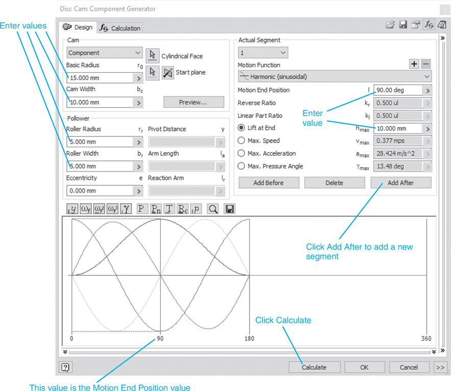
Figure 15-3
![]() Enter a Basic Radius of 15.00, a Cam Width of 10.00, a Roller Radius of 5.00, and a Roller Width of 5.00.
Enter a Basic Radius of 15.00, a Cam Width of 10.00, a Roller Radius of 5.00, and a Roller Width of 5.00.
These values are unique to this example.
![]() Enter a Lift at End value of 10.00.
Enter a Lift at End value of 10.00.
This value is noted as hmax.
![]() Click the Add After box.
Click the Add After box.
A third segment will appear to the right of the leftmost segment.
![]() Click the rightmost of the three segments and drag the rightmost vertical line of the segment to the 360° line. This movement can also be accomplished by clicking the Motion End Position box, entering a value of 360, and clicking the Calculate box.
Click the rightmost of the three segments and drag the rightmost vertical line of the segment to the 360° line. This movement can also be accomplished by clicking the Motion End Position box, entering a value of 360, and clicking the Calculate box.
![]() Set the end position of the leftmost segment for 90 and the end position of the middle segment for 270 by clicking the individual segment, entering the appropriate value in the Motion End Position box, and clicking the Calculate box.
Set the end position of the leftmost segment for 90 and the end position of the middle segment for 270 by clicking the individual segment, entering the appropriate value in the Motion End Position box, and clicking the Calculate box.
See Figure 15-4.

Figure 15-4
![]() Enter a Motion Function of Cycloidal (extended sinusoidal) for the first and third segments.
Enter a Motion Function of Cycloidal (extended sinusoidal) for the first and third segments.
![]() Click the Calculate button to implement the new Motion Functions.
Click the Calculate button to implement the new Motion Functions.
The middle segment of the cam, segment 2, is a dwell motion. Dwell portions of a cam have a constant radius so the follower will not move up or down during the dwell. Dwell segments are created, in this example, by having the Lift at End value of the first segment set at 10 and the Lift at End value for the second segment also set for 10. The Lift at End value for the third segment is 0.000.
Figure 15-5 shows the Calculation portion of the Disc Cam Component Generator dialog box. Note that the hmax value is 10.000 mm and the hmin value is 0.000 mm.

Figure 15-5
![]() Click OK.
Click OK.
The File Naming dialog box will appear.
![]() Click OK.
Click OK.
Figure 15-6 shows the resulting cam.
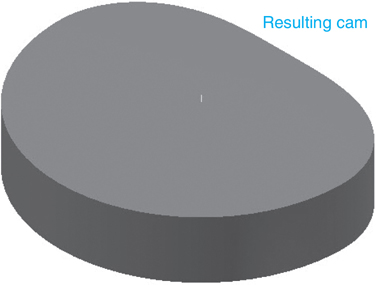
Figure 15-6
Exercise 15-2 Adding a Hole to a Cam
![]() Locate the cursor on the cam, right-click the mouse, and click the Open option.
Locate the cursor on the cam, right-click the mouse, and click the Open option.
See Figure 15-7.

Figure 15-7
![]() Right-click the mouse and click the Edit option.
Right-click the mouse and click the Edit option.
See Figure 15-8.

Figure 15-8
![]() Click the house-shaped icon, the Home tool, above the ViewCube and create an Isometric View, then right-click again and click the New Sketch option.
Click the house-shaped icon, the Home tool, above the ViewCube and create an Isometric View, then right-click again and click the New Sketch option.
See Figure 15-9.

Figure 15-9
![]() Create a Point, Center Point.
Create a Point, Center Point.
See Figure 15-10.

Figure 15-10
![]() Right-click the mouse and click the Finish 2D Sketch option.
Right-click the mouse and click the Finish 2D Sketch option.
![]() Click the Hole tool and enter the values shown.
Click the Hole tool and enter the values shown.
![]() Click OK.
Click OK.
![]() Right-click the mouse and click the Finish Edit option.
Right-click the mouse and click the Finish Edit option.
See Figure 15-11.

Figure 15-11
The cam will appear. See Figure 15-12.
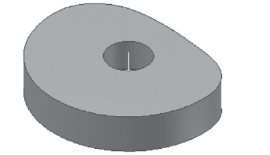
Figure 15-12
Sample Problem SP15-1
Design and draw a cam that meets the following specifications:
All linear dimensions are in millimeters.
Base circle = Ø80
Dwell = 45°
Rise 5 mm using harmonic motion over 90°
Dwell 45°
Rise 5 mm using harmonic motion over 90°
Drop 10 mm using parabolic with linear part motion in 90°
Bore = Ø12
Cam width = 10
Roller radius = 8
Roller width = 10
![]() Create a drawing using the Standard (mm).iam format.
Create a drawing using the Standard (mm).iam format.
![]() Click the Design tab.
Click the Design tab.
![]() Select the Disc Cam tool.
Select the Disc Cam tool.
The Disc Cam Component Generator dialog box will appear. See Figure 15-13.
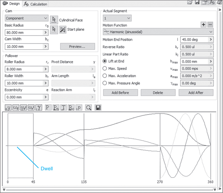


Figure 15-13
![]() Enter the cam values.
Enter the cam values.
![]() Click the Add After box.
Click the Add After box.
The cam will require five segments to define its motion. Segments can be added by using the Add Before or Add After option on the Disc Cam Component Generator.
![]() Complete the displacement diagram using the given specifications.
Complete the displacement diagram using the given specifications.
Isolate each of the five segments and enter the appropriate values. For example, the first segment is a dwell for 45°. Set the Motion End Position for 45.00 deg and Lift at the End for 00.00.
![]() Click Calculate after each segment input has been completed, then click OK.
Click Calculate after each segment input has been completed, then click OK.
Figure 15-14 shows the finished cam.
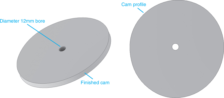
Figure 15-14
Cams and Followers
Figure 15-15 shows a cam that was previously created in SP15-1.

Figure 15-15
Start a New Assembly
![]() Create a new Standard (mm).iam drawing.
Create a new Standard (mm).iam drawing.
![]() Use the Place Component tool and add the cam created in SP15-1.
Use the Place Component tool and add the cam created in SP15-1.
![]() Click the Create tool located on the Component panel.
Click the Create tool located on the Component panel.
See Figure 15-16.

Figure 15-16
Exercise 15-3 Creating a Follower
![]() Name the new component FOLLOWER.
Name the new component FOLLOWER.
The Create In-Place Component dialog box will appear. See Figure 15-16.
![]() Click the Browse Templates box.
Click the Browse Templates box.
The Open Template dialog box will appear.
![]() Click the Metric tab.
Click the Metric tab.
The Open Template dialog box will change.
![]() Select the Standard (mm).ipt format; click OK.
Select the Standard (mm).ipt format; click OK.
The Create In-Place Component dialog box will appear.
![]() Click OK.
Click OK.
![]() Move the cursor into the drawing area and click the left mouse button.
Move the cursor into the drawing area and click the left mouse button.
You are now in Sketch mode. See Figure 15-17. The sketch plane is aligned with the sketch plane used to create the cam.
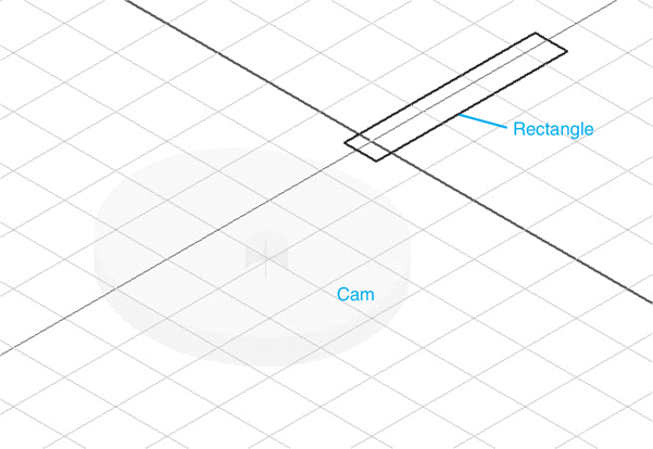
Figure 15-17
![]() Use the Rectangle tool under the Sketch tab and sketch the approximate shape of the FOLLOWER.
Use the Rectangle tool under the Sketch tab and sketch the approximate shape of the FOLLOWER.
![]() Use the Dimension tool and size a rectangular follower to 10× 60 as shown.
Use the Dimension tool and size a rectangular follower to 10× 60 as shown.
![]() Click the right mouse button and select Finish 2D Sketch, right-click the mouse again, and select the Finish Edit option.
Click the right mouse button and select Finish 2D Sketch, right-click the mouse again, and select the Finish Edit option.
![]() Right-click the rectangle and select the Edit option. Use the Extrude tool and extrude the rectangle 10 mm.
Right-click the rectangle and select the Edit option. Use the Extrude tool and extrude the rectangle 10 mm.
![]() Right-click the mouse and select Finish Edit.
Right-click the mouse and select Finish Edit.
See Figure 15-18.

Figure 15-18
![]() Use the Constrain tools Tangent and Flush to constrain the follower to the cam.
Use the Constrain tools Tangent and Flush to constrain the follower to the cam.
See Figure 15-19.

Figure 15-19
The Move and Rotate Component tool may have to be used to position the follower so it can be constrained.
Exercise 15-4 Creating a Follower Guide
![]() Right-click the mouse, click the Create Component tool, and create a new component named GUIDE. Use the Standard (mm).ipt format. See Figure 15-20.
Right-click the mouse, click the Create Component tool, and create a new component named GUIDE. Use the Standard (mm).ipt format. See Figure 15-20.
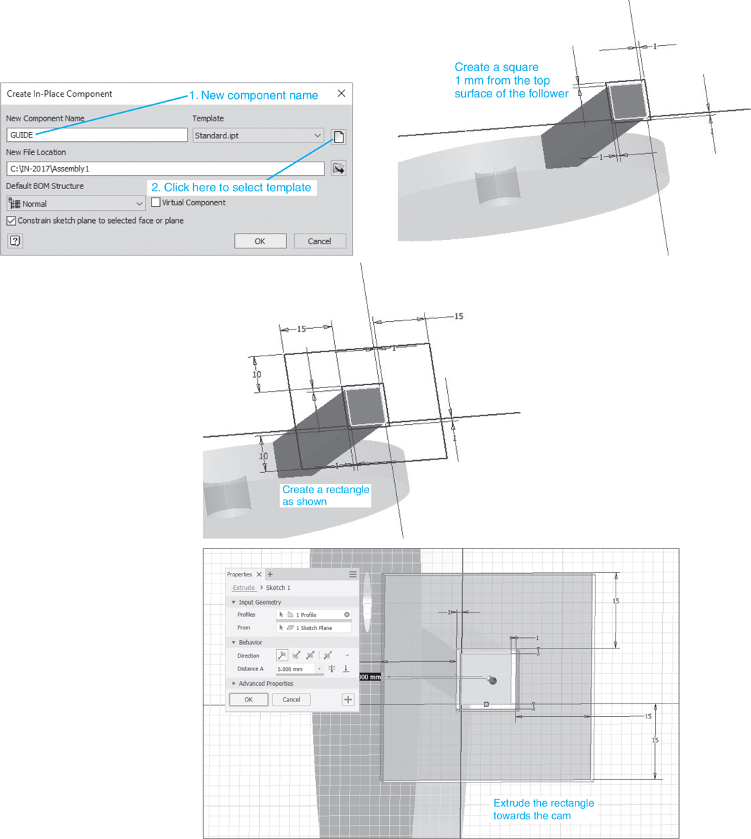
Figure 15-20
![]() Click the top surface of the follower to create a new sketch plane.
Click the top surface of the follower to create a new sketch plane.
![]() Click the Project Geometry tool located on the Draw panel under the Sketch tab, and click the four lines of the top surface of the follower. Right-click the mouse and select the Done option.
Click the Project Geometry tool located on the Draw panel under the Sketch tab, and click the four lines of the top surface of the follower. Right-click the mouse and select the Done option.
![]() Sketch a rectangle around the projected top surface of the follower, then use the Dimension tool to define a 1-mm clearance between the guide and the follower.
Sketch a rectangle around the projected top surface of the follower, then use the Dimension tool to define a 1-mm clearance between the guide and the follower.
![]() Sketch a second rectangle around the first rectangle as shown, then right-click the mouse and select the Done option, then the Finish Sketch option.
Sketch a second rectangle around the first rectangle as shown, then right-click the mouse and select the Done option, then the Finish Sketch option.
![]() Use the Extrude tool to add a 5-mm thickness to the guide.
Use the Extrude tool to add a 5-mm thickness to the guide.
![]() Right-click the mouse and select the Finish Edit option.
Right-click the mouse and select the Finish Edit option.
See Figure 15-21.

Figure 15-21
There are many different types of cam followers. Figure 15-22 shows four different types. As a cam turns, the follower is pushed up and down. A spring is often used to force the follower to stay in contact with the cam surface.
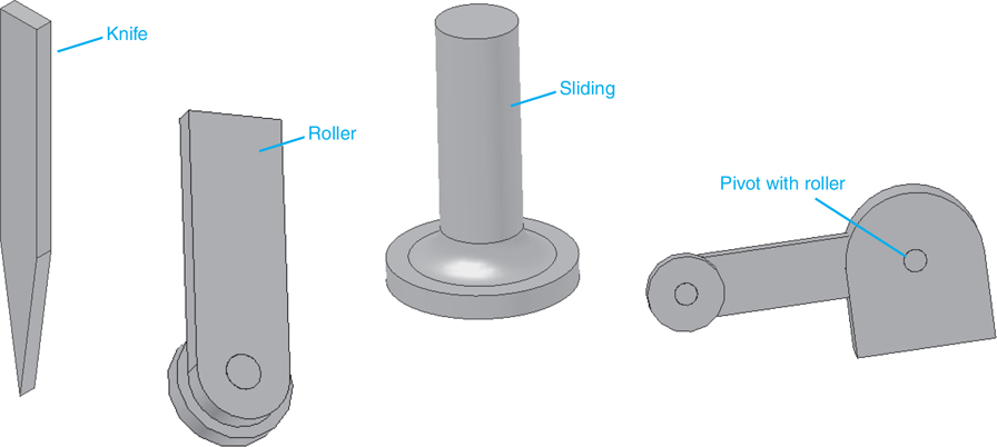
Figure 15-22
Chapter Summary
This chapter explained and illustrated how to draw and design cams, which are eccentric objects that convert rotary motion into linear motion. Displacement diagrams were defined and used to generate cams with the Disc Cam tool located under the Design tab. A follower was created, and the cam and follower assembly was animated.
Chapter Test Questions
Multiple Choice
Circle the correct answer.
1. Which of the following is not a type of cam follower?
a. Rectangular
b. Knife
c. Sliding
d. Roller
2. The basic shape about which a cam is created is called the
a. Roller radius
b. Cylindrical face
c. Base circle
d. Eccentricity
3. The acceleration and forces in a cam follower are affected by
a. The cam’s material
b. The shape of the cam’s profile surface
c. Poisson’s ratio
4. Why are keys used with cams?
a. To control their pressure angles
b. To transfer rotary motion for the driving shaft
c. To change the effects of the basic radius
5. Which of the following is not a standard cam material available in Inventor?
a. Steel SAE 1030
b. Malleable cast iron 33-8
c. Aluminum Alloy Alclad 7075-T6
d. #2 Pine
True or False
Circle the correct answer.
1. True or False: Cams are eccentric objects that convert rotary motion into linear motion.
2. True or False: When a cam has a constant radius it creates a dwell motion.
3. True or False: The base circle of a cam is its outside diameter.
4. True or False: The part that contacts the profile surface of a cam is called a follower.
5. True or False: Cams can be animated.
Chapter Projects
Project 15-1: Millimeters
Draw the Cam Support Assembly shown in Figure P15-1A through P15-1I. For this example, the nominal dimensions for the bearings are as follows. More detailed dimensions can be found in the Content Center.
DIN625—SKF 6203 (ID × OD × THK) 17 × 40 × 10
DIN625—SKF 634 4 × 13 × 4
GB 2273.2—87—7/70 8 × 18 × 5
The nominal dimensions for the rectangular key are 5 × 5 × 16.
The values for the compression spring are as follows:
Wire diameter = 1.5
Inside diameter = 9.0
Loose spring length = 24
Preload spring length = 23
Fully loaded = 20
Working spring length = 21
Right coil direction
Active coils = 10.125
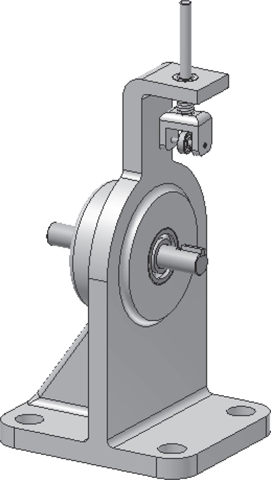
Figure P15-1A

Figure P15-1B
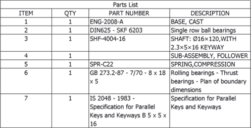
Figure P15-1C

Figure P15-1D
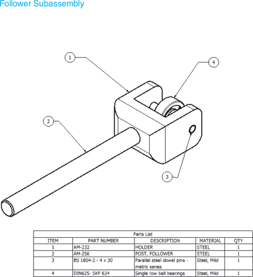
Figure P15-1E
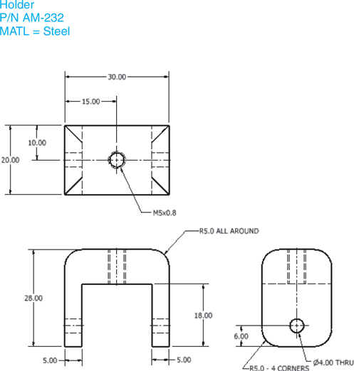
Figure P15-1F

Figure P15-1G
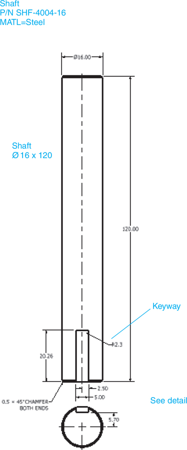
Figure P15-1H

Figure P15-1I
Project 15-2: Millimeters
A. Draw the following cam:
Base circle = R73.0
Face width = 16.0
Rise 10.0 using harmonic motion in 90°
Dwell for 180°
Fall 10.0 using harmonic motion in 90°
Bore = Ø16.0
Keyway = 2.3 × 5 × 16 with a radius value of 2.3
Follower diameter = 16
Follower width = 4
B. Mount the cam into the Cam Support Assembly defined in Project 15-1. See Figure P15-2.
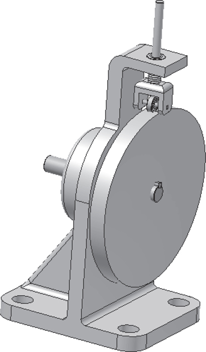
Figure P15-2
Project 15-3: Millimeters
A. Draw the following cam:
Base circle = Ø73.0
Face width = 16.0
Rise 8.0 using double harmonic motion—Part 1 motion in 90°
Dwell for 45°
Rise 6.0 using double harmonic motion—Part 1 motion in 90°
Dwell for 45°
Fall 14.0 using double harmonic motion—Part 1 motion in 90°
Bore = Ø16.0
Keyway = 2.3 × 5 × 16 with a radius value of 2.3
Follower diameter = 16
Follower width = 4
B. Mount the cam into the Cam Support Assembly defined in Project 15-1.
Project 15-4: Millimeters
A. Draw the following cam and add a Ø24.0 × 16.0 hub. Place a Ø16 hole through the hub and cam. Add an M4 hole though the hub located 10.0 from the top surface of the hub, and insert an M4 × 4.0 CSN 02 1181 Set Screw.
Base circle = Ø73.0
Face width = 16.0
Rise 6.0 using cycloidal motion in 45°
Dwell for 45°
Rise 6.0 using cycloidal motion in 90°
Dwell for 45°
Fall 12.0 using cycloidal motion in 90°
Bore = Ø16.0
Keyway = 2.3 × 5 × 16 with a radius value of 2.3
Follower diameter = 16
Follower width = 4
B. Design
Mount the cam into the Cam Support Assembly defined in Project 15-1. Modify the shaft presented in Project 15-1 by removing the keyway. Assign the modified shaft a new part number, SHT-466E.
Project 15-5: Millimeters
A. Draw the following cam:
Base circle = Ø73.0
Face width = 16.0
Rise 12.0 using harmonic motion in 90°
Dwell for 180°
Fall 12.0 using harmonic motion in 90°
Follower diameter = 16
Follower width = 4
B. Design
Make the following modifications, then mount the cam into the Cam Support Assembly defined in Project 15-1.
Make the cam’s bore 20.0.
Modify the shaft to have a Ø20.0.
Select a new key based on the Ø20.0 shaft, and add the appropriate keyway to the shaft and cam.
Select a new bearing to accept the Ø20.0 shaft.
Modify the hole in the Cast Base to accept the outside diameter of the selected bearing.
Consider using a counterbored hole to mount the bearing.