This chapter presents a step-by-step introduction to Inventor 2020. When the program is first accessed, the Get Started panel will appear. See Figure 1-1.
Figure 1-1
Inventor uses a system of tabs and panels to present commands. In Figure 1-1, the tab is Get Started, and the panels are Launch, My Home, and New Features. Within each panel is a series of commands. On the Launch panel are the commands New, Open, Projects, and Open Samples.
To Start a New Drawing
There are two ways to start a New drawing; click the New tool located under the Get Started tab, or click the Part tool, as shown in Figure 1-1.
Clicking the Part tool will let you jump directly to a drawing screen. The drawing will automatically be set to the default values. In this example, the default values are decimal inches; the default values can be edited.
Clicking the New tool will allow you to select drawing units and the type of drawing you want.
Click the New tool located on the Launch panel under the Get Started tab.
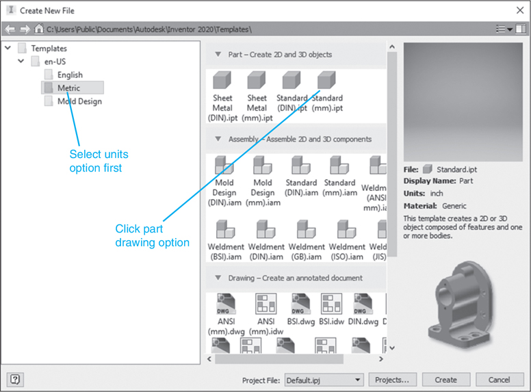
The Create New File dialog box will appear. See Figure 1-2.
Figure 1-2
Click the type of drawing you want to create.
There are many options for creating drawings with four different types of files. These files are categorized using four different extensions. The extensions are defined as follows:
.ipt: Part files for either 3D model drawings or sheet-metal drawings. These files are for individual parts.
.iam: Assembly drawings and weldments. Assembly drawings are formed by combining .ipt files.
.ipn: Presentation files. These files are used to create exploded assembly drawings.
.idw: Drawing layout files. These files are used to create orthographic views from already existing part, assembly, and presentation drawings
The first type of drawing created in this text is a Standard (mm).ipt drawing. The mm indicates that the drawing units are millimeters. The first screen to appear will have a colored background. For this text, the background color was changed to a Presentation format to make the illustrations easier to read. Your screen may have a different background.
To Change the Screen’s Background Color
Click the Tools tab.
Click the Application Options tool on the Options panel.
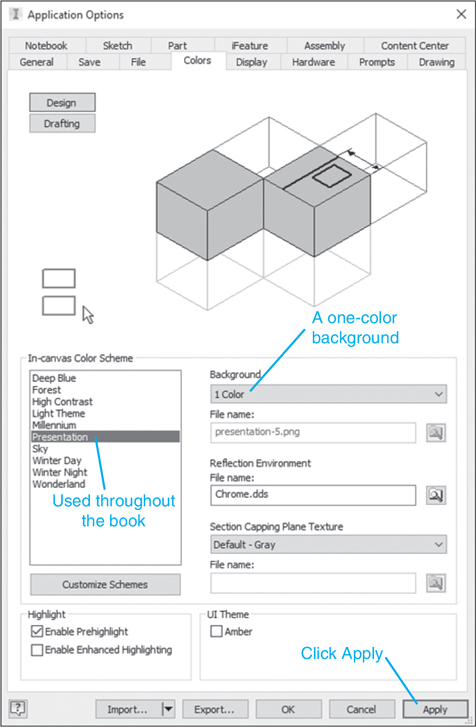
The Application Options dialog box will appear. See Figure 1-3.
Figure 1-3
Click the Colors tab on the Application Options dialog box.
Select a color scheme.
In this example, the Presentation color scheme was selected and a one-color background rather than a gradient. This background color will be used throughout the text.
Click OK.
Creating a First Sketch
This section shows how to set up, create, and save a first drawing. The intent is to walk through a simple drawing in order to start to understand how Inventor functions.
Click the Get Started tab.
Click the New tool on the Launch panel.
The New File dialog box will appear. See Figure 1-2.
Click the Metric tab.
The Metric tab defines all drawing dimension values in millimeters.
Click the Standard (mm).ipt tool; click the Create box.
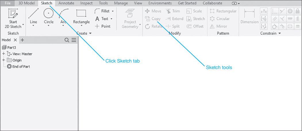
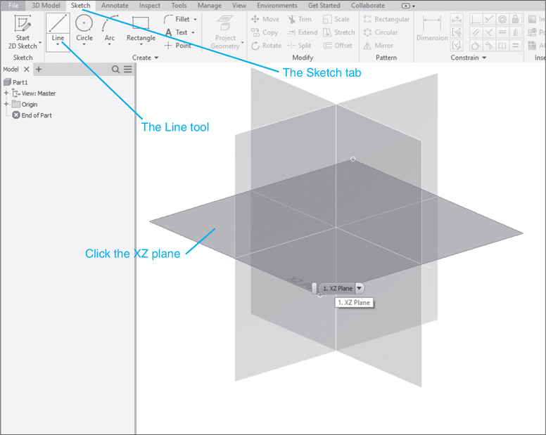
Click the Sketch tab.
The panels at the top of the screen will change to the Sketch panels.
Click the Line tool located in the Draw panel under the Sketch tab.
See Figure 1-5. You must define which plane you want to work on.
Figure 1-5
Select the XZ plane.
The screen will rotate so as to create a direct view of the XZ plane. The view is like a blank sheet of drawing paper. We are looking along the Y-axis at the XZ plane. The grid background has been turned off for clarity.
Click a starting point for the line, release the mouse button, and drag the cursor across the drawing screen.
Draw a horizontal line, that is, one at 0°.
The length need not be a specific value. See Figure 1-6. The line’s length could be defined by entering a numeric value that will appear in the box above the line. The box will disappear once the line’s endpoint is defined.
Figure 1-6
Click the mouse to define the end of the line. Drag the cursor downward to create a vertical line, that is, one at 90° to the first line.
Draw a second horizontal line parallel to the first line. Continue the line until a broken line appears from the starting point of the first line.
This broken line indicates that the endpoint of the second horizontal line is now aligned with the starting point of the first line.
Draw a second vertical line to complete the rectangle.
Right-click the mouse and select the OK option.
To Size the Rectangle
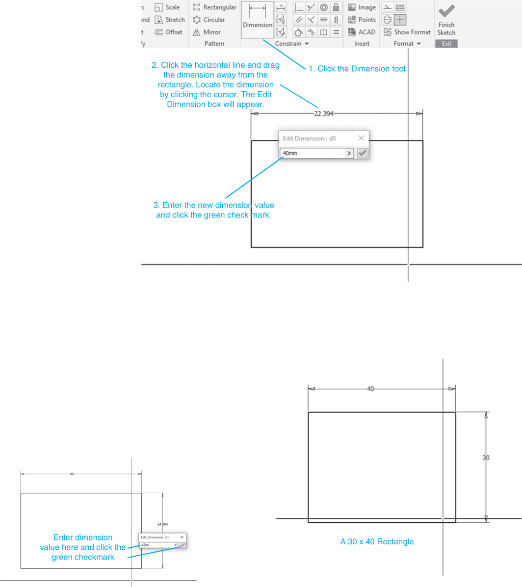
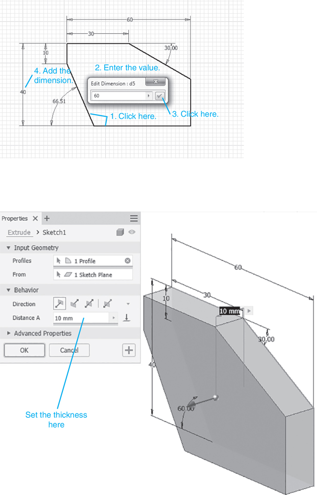
The rectangle shown in Figure 1-6 was drawn without regard to dimension values; that is, it was sketched. The dimension values must be entered. See Figure 1-7.
Figure 1-7
NOTE: Do not click the Finish 2D Sketch; continue working on the sketch.
Click the Dimension tool, click the top horizontal line, and move the cursor away from the line. Click the mouse to locate the new dimension.
The Edit Dimension dialog box will appear.
Enter the desired value and click the green (OK) checkmark or press the <Enter> key.
The length of the rectangle will change to the entered dimension value.
Click the vertical line and move the cursor away from the line. Click the mouse to locate the new dimension.
Enter the desired value and click the green (OK) checkmark or press the <Enter> key.
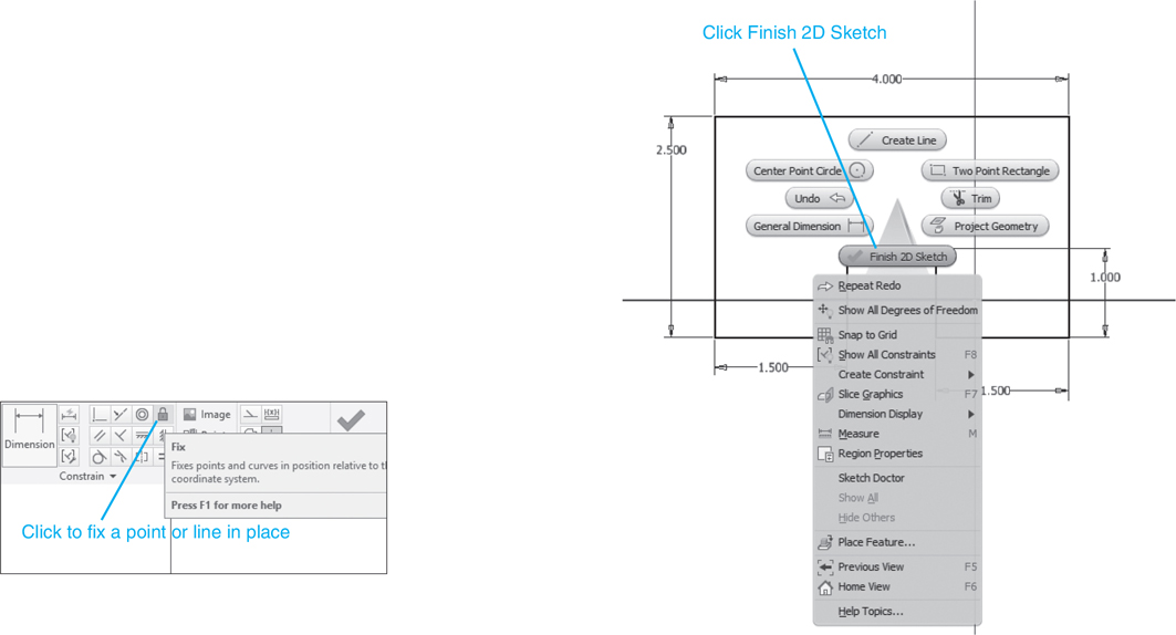
Right-click the mouse and select the Finish 2D Sketch option.
The screen will change to a 3D view of the rectangle. If needed, click the front surface on the ViewCube to return the 2D view to the XY plane. Use the mouse wheel to size the rectangle to fit the screen.
To Edit an Existing Dimension
The size of an object can be edited by changing the dimensions. For example, say we wish to change the size of the 30 × 40 rectangle to 35 × 50. We can edit the existing drawing. The drawing view was returned to 2D for this example. The dimensions could be edited with the screen in the 3D orientation.
Double-click the 30 dimension.
The dimension value box will appear. See Figure 1-8.
Figure 1-8
Change the dimension value to 35.
Click the green checkmark.
The dimension value will change, as will the shape of the rectangle.
Repeat the procedure to change the 40 value to 50.
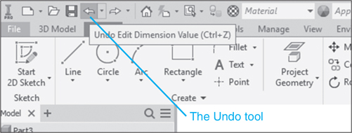
The Undo Tool
The Undo tool is used to undo commands. The commands will be undone in the reverse order of the sequence in which they were entered.
To Undo a Series of Commands
Click the Undo tool located at the top of the screen.
Use the Undo command to return the 35 × 50 rectangle to the original 30 × 40 rectangle.
Creating a Solid Model
The 30 × 40 rectangle will now be used to create a solid object 15.0 mm thick.
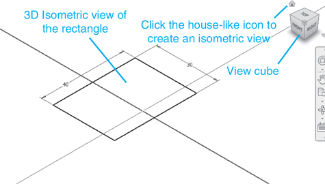
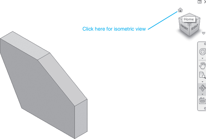
Click the 3D Model tab located near the top left corner of the screen, and, if needed, click the house-like Home icon next to the ViewCube.
The Home tool will appear as the cursor is move to the View Cube.
See Figure 1-10. The screen will change view orientation to 3D Isometric view.
Figure 1-10
Click the Extrude tool located in the Create panel under the Model tab.
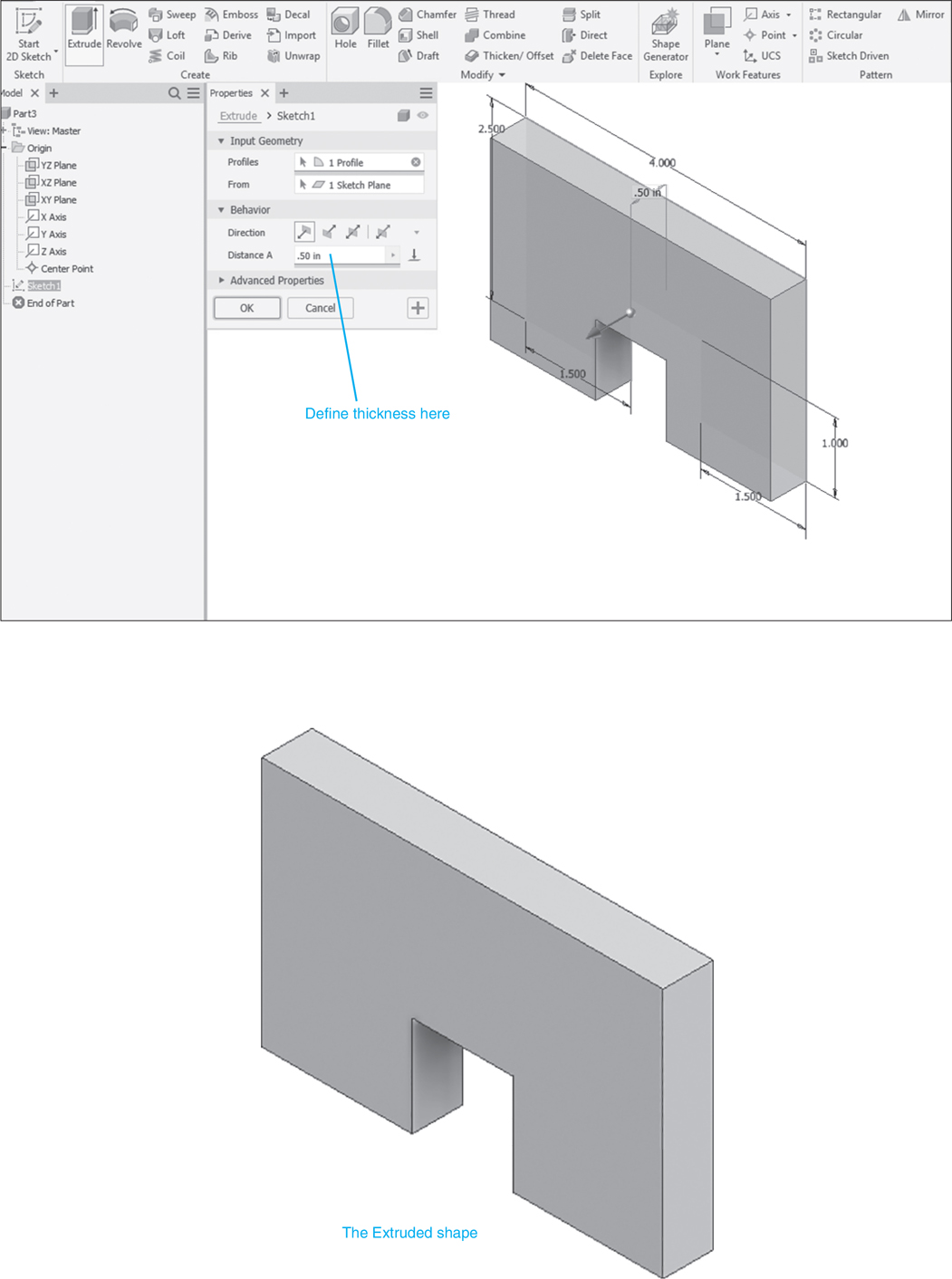
The Extrude dialog box will appear. See Figure 1-11. In this example, the default thickness value is 10 mm.
Figure 1-11
Change the thickness value in the Extrude dialog box to 15; click OK.
The 30 × 40 rectangle has been used to create a 15 × 30 × 40 box (rectangular prism). This is a solid model.
To Add a Hole
Inventor allows you work on only one plane at a time. To create a hole, create a new drawing plane on the top surface of the box, add a circle to the plane, and then make sure the directional arrow is pointing through to create a hole. See Figure 1-12.
Figure 1-12
Move the cursor to the top surface of the box and right-click the mouse.
The top surface will change color when selected.
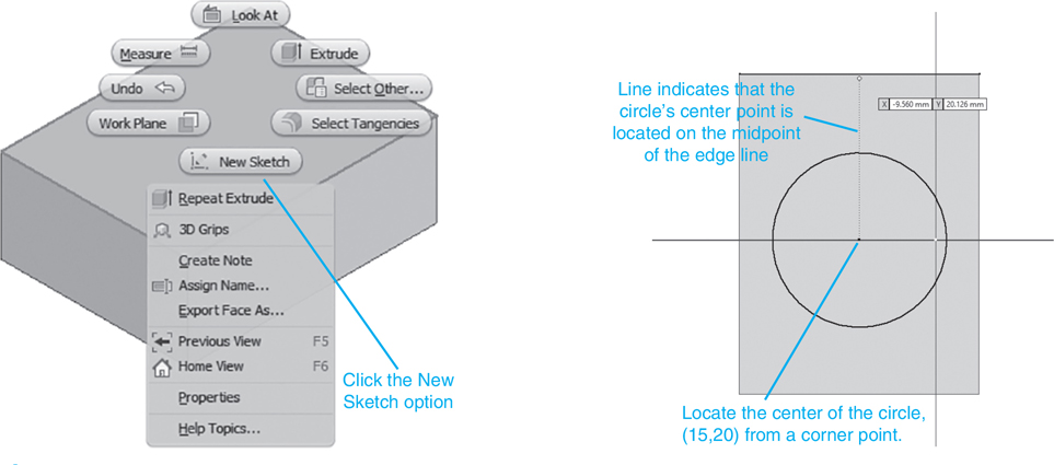
Click the New Sketch option.
The box will change orientations so that you are looking directly onto the top surface.
Click the Circle tool on the Draw panel under the Sketch tab.
Locate the circle on the center point of the top surface by moving the cursor around the edge lines until the midpoints are identified. When the cursor intersects an edge line’s midpoint, a green circle will appear. Move the cursor away from the midpoint and locate the other edge line midpoint. Move the cursor to the center of the surface. Broken lines will appear from the midpoints of the edge lines of the surface. Locate the center point of the circle on the center point of the top surface of the box.
Use the Dimension tool from the Constraint panel under the Sketch tab and define the diameter of the circle as 15.0 mm.
Right-click the top surface and select the Finish 2D Sketch option.
Click the Extrude tool on the Create panel under the Model tab.
The Extrude dialog box will appear.
Click the circle on the top surface.
Define the depth of the hole as 15 mm or greater.
Be sure to have the extrusion pointing downward into the box.
Click OK.
To Save a Drawing
Click the File tab located under the I icon at the top left of the screen, and select the Save As option.
See Figure 1-13. The Save as dialog box will appear.
Figure 1-13
Save the drawing as 30 × 40 × 15 Box; click Save. See Figure 1-14.
Figure 1-14
There are other ways to create holes. These will be discussed later in the text.
Sample Problem SP1-1
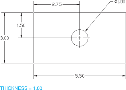
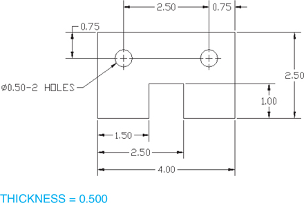
This section shows how to draw the problem presented in Figure P1-2 in the Chapter Project. The dimensions are in inches.
Start a New drawing. Click the English tab, and select the Standard (in.).ipt format.
Click the arrowhead next to the Origin heading in the Browser Box and select the XY Plane option. Move the cursor into the drawing area, right-click the mouse, and select the New Sketch option.
Click the Line tool located on the Draw panel under the Sketch tab and sketch the approximate shape of the object.
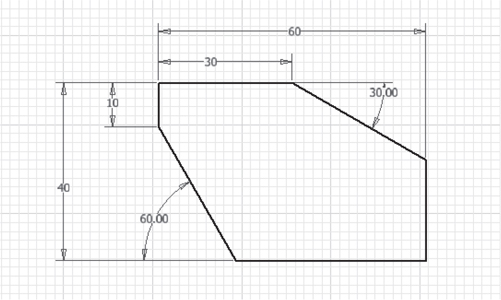
See Figure 1-17. This drawing is a sketch and uses only approximate dimensions, but all angles are sketched at 90°. The lower lines of the sketch were aligned.
Figure 1-17
Click the Dimension tool and add the dimensions as presented in Figure P1-2 in the Chapter Project.
If, when the 1.000 dimension is applied, one side of the shape moves but the other side does not, we could align the two bottom edges by adding a second 2.500 dimension to the right edge line, but we can also use a Constraint option.
Click the Undo tool and return the drawing to its original shape without the 1.000 dimension.
Click the Fix tool located on the Constraint panel under the Sketch tab.
The Fix constraint looks like a padlock.
Click one of the lines.
This will fix the line; that is, it will not move when changes are made. The Fix constraint will cause the 1.000 dimension to be absorbed by moving the horizontal portion of the slot.
Add the 1.000 dimension for the slot.
Right-click the mouse and select the Finish 2D Sketch option.
A house-like icon will appear. This is the Home tool.
Click the Home tool.
The object will return to its original isometric shape.
Chapter Summary
This chapter showed how to get started using Inventor 2020. It showed how to start a new drawing, how to create 2D sketches, and how to change the sketches into dimensioned drawings. The drawings were then used to create solid 3D models. Sample problems showed how to add holes and angular edges to 3D models.
Chapter Test Questions
Multiple Choice
Circle the correct answer.
1. Which of the following formats is used to create Inventor sketches?
a. Weldment.iam
b. Standard (in).ipt
c. Standard.ipn
d. ISO.dwg
2. The Dimension tool is used to perform which of the following?
a. Add dimensions to a drawing
b. Create isometric views
c. Change the orientation of a drawing
3. The Extrude tool is located on the
a. Model panel
b. Sketch panel
c. Draw panel
d. Create panel
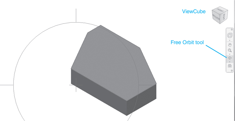
4. The Free Orbit tool is used to
a. Remove the drawing from the drawing screen
b. Allow the drawing to be rotated into different orientations
c. Allow the drawing to be used on different drawings
d. Free the drawing from its existing file name
5. Holes are created in parts using
a. The Extrude Cut tool
b. The Extrude tool
c. A presentation drawing
d. The Project Geometry tool
Matching
Write the number of the correct answer on the line.
Column A
Column B
a. Save As ______
1. The format used to start a new metric drawing
b. Home ______
2. Used to add thickness to a sketch
c. Standard (mm).ipt ______
3. Used to define the file name of a drawing
d. Extrude ______
4. Used to change a drawing’s orientation to isometric
e. Extrude Cut ______
5. Used to create a hole from a circle
True or False
Circle the correct answer.
1. True or False: Sketches are created using the ANSI (mm).idw format.
2. True or False: Drawings with inch dimensions are created using the Standard (in.).ipt format.
3. True or False: The ViewCube is used to change the orientation of a drawing.
4. True or False: Holes can be created using Hole and Extrude Cut tools.
5. True or False: The Fix constraint is used to fix a point in space.
Chapter Project
Project 1-1
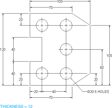
Sketch the shapes shown in Figures P1-1 through P1-10, then create solid models using the specified thickness values.
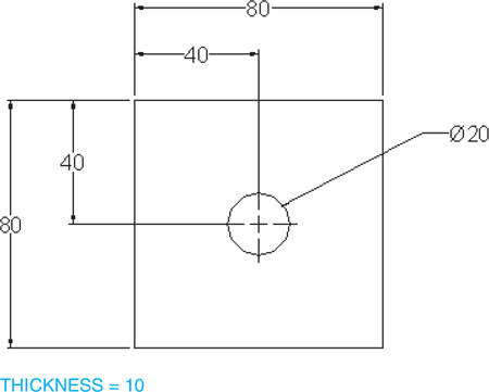
Figure P1-1 Inches
Figure P1-2 Inches
Note
This exercise is presented in Sample Problem SP1-1.