Chapter 1
Single-Area OSPFv2 Concepts
Objectives
Upon completion of this chapter, you will be able to answer the following questions:
What are the basic features and characteristics of OSPF?
What OSPF packet types are used in single-area OSPF?
How does single-area OSPF operate?
Key Terms
This chapter uses the following key terms. You can find the definitions in the Glossary.
Open Shortest Path First (OSPF) page 3
database description (DBD) packet page 4
link-state request (LSR) packet page 4
link-state update (LSU) packet page 4
link-state acknowledgment (LSAck) packet page 4
link-state database (LSDB) page 4
shortest-path first (SPF) algorithm page 5
area border router (ABR) page 9
link-state packet (LSP) page 13
designated router (DR) page 15
backup designated router (BDR) page 15
Introduction (1.0)
Imagine that it is time for your family to visit your grandparents. You pack your bags and load them into the car. But the process takes a bit longer than you planned, and now you are running late. You pull out your map. There are three different routes. One route is no good because there is a lot of construction on the main road, and it is temporarily closed. Another route is very scenic, but it takes an additional hour to get to your destination. The third route is not as pretty but it includes a highway, which is much faster. In fact, it is so much faster that you might actually be on time if you take it.
In networking, packets do not need to take the scenic route. The fastest available route is always the best. Open Shortest Path First (OSPF) is designed to find the fastest available path for a packet from source to destination. This chapter covers the basic concepts of single-area OSPFv2. Let’s get started!
OSPF Features and Characteristics (1.1)
OSPF is a popular multivendor, open-standard, classless link-state routing protocol. In this section you will learn how OSPF operates.
Introduction to OSPF (1.1.1)
This section provides a brief overview of Open Shortest Path First (OSPF), including single-area OSPF and multiarea OSPF. OSPFv2 is used for IPv4 networks, while OSPFv3 is used for IPv6 networks. In addition, OSPFv3 with address families supports both IPv4 and IPv6. The primary focus of this chapter is on single-area OSPFv2.
OSPF is a link-state routing protocol that was developed as an alternative for the distance vector protocol Routing Information Protocol (RIP). RIP was an acceptable routing protocol in the early days of networking and the internet. However, RIP’s reliance on hop count as the only metric for determining best route quickly became problematic. Using hop count does not scale well in larger networks with multiple paths of varying speeds. OSPF has significant advantages over RIP in that it offers faster convergence and scales to much larger network implementations.
OSPF is a link-state routing protocol that uses the concept of areas. A network administrator can divide the routing domain into distinct areas that help control routing update traffic. A link is an interface on a router. A link is also a network segment that connects two routers, or a stub network such as an Ethernet LAN that is connected to a single router. Information about the state of a link is known as link-state information; this information includes the network prefix, prefix length, and cost.
This chapter covers basic, single-area OSPF implementations and configurations.
Components of OSPF (1.1.2)
All routing protocols share similar components. They all use routing protocol messages to exchange route information. The messages help build data structures, which are then processed using a routing algorithm.
The components of OSPF are as follows:
Routing protocol messages
Data structures
Algorithm
Routing Protocol Messages
Routers running OSPF exchange messages to convey routing information using five types of packets. These packets, as shown in Figure 1-1, are as follows:
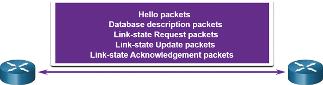
Figure 1-1 OSPF Packets
These packets are used to discover neighboring routers and also to exchange routing information to maintain accurate information about the network.
Data Structures
OSPF messages are used to create and maintain three OSPF databases:
Adjacency database: This creates the neighbor table.
Link-state database (LSDB): This creates the topology table.
Forwarding database: This creates the routing table.
Each of these tables contains a list of neighboring routers to exchange routing information. The tables are kept and maintained in RAM. In Table 1-1, take a particular note of the command used to display each table.
Table 1-1 OSPF Databases
Database |
Table |
Description |
Adjacency database |
Neighbor table |
|
Link-state database |
Topology table |
|
Forwarding database |
Routing table |
|
Algorithm
A router builds a topology table by using results of calculations based on Dijkstra’s algorithm. The shortest-path first (SPF) algorithm is based on the cumulative cost to reach a destination.
The SPF algorithm creates an SPF tree by placing each router at the root of the tree and calculating the shortest path to each node, as shown in Figure 1-2. The SPF tree is then used to calculate the best routes. OSPF places the best routes into the forwarding database, which is used to make the routing table.
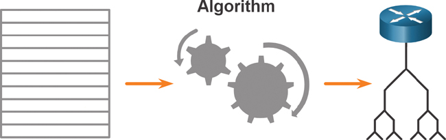
Figure 1-2 Algorithm Creates SPF Tree
Link-State Operation (1.1.3)
To maintain routing information, OSPF routers complete a generic link-state routing process to reach a state of convergence. In the following figures, the topology consists of five routers. The links between the routers have been labeled with cost values. In OSPF, cost is used to determine the best path to the destination. A router completes the following link-state routing steps:
Step 1. Establish neighbor adjacencies.
Step 2. Exchange link-state advertisements.
Step 3. Build the link-state database.
Step 4. Execute the SPF algorithm.
Step 5. Choose the best route.
1. Establish Neighbor Adjacencies
OSPF-enabled routers must recognize each other on the network before they can share information. An OSPF-enabled router sends Hello packets out all OSPF-enabled interfaces to determine if neighbors are present on those links, as shown in Figure 1-3. If a neighbor is present, the OSPF-enabled router attempts to establish a neighbor adjacency with that neighbor.
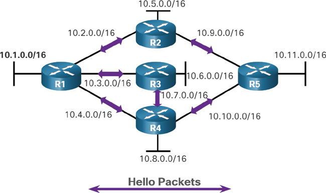
Figure 1-3 Routers Exchange Hello Packets
2. Exchange Link-State Advertisements
After adjacencies are established, routers exchange link-state advertisements (LSAs), as shown in Figure 1-4. An LSA contains the state and cost of each directly connected link. Routers flood their LSAs to adjacent neighbors. Adjacent neighbors receiving the LSA immediately flood the LSA to other directly connected neighbors, until all routers in the area have all LSAs.
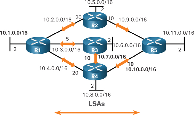
Figure 1-4 Routers Exchange LSAs
3. Build the Link-State Database
After LSAs are received, OSPF-enabled routers build the topology table (LSDB) based on the received LSAs, as shown in Figure 1-5. This database eventually holds all the information about the topology of the area.
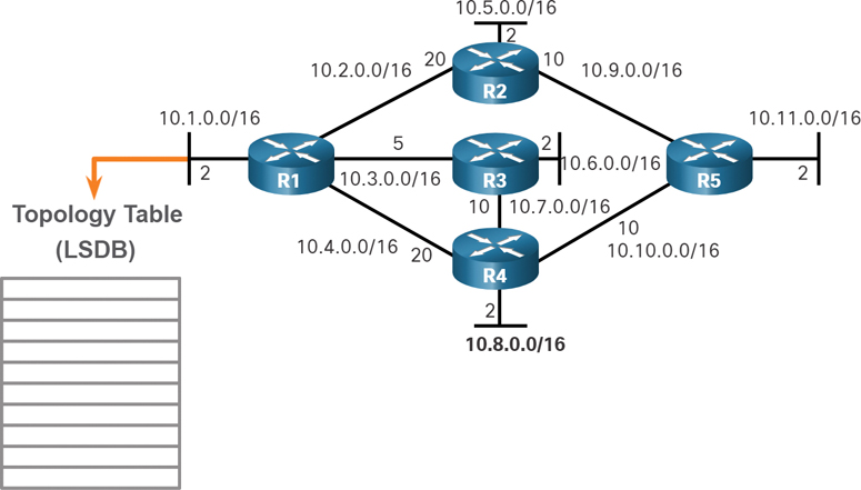
Figure 1-5 R1 Creates Its Topology Table
4. Execute the SPF Algorithm
When the LSDB is built, routers then execute the SPF algorithm. The gears in Figure 1-6 for this step are used to indicate the execution of the SPF algorithm. The SPF algorithm creates the SPF tree.
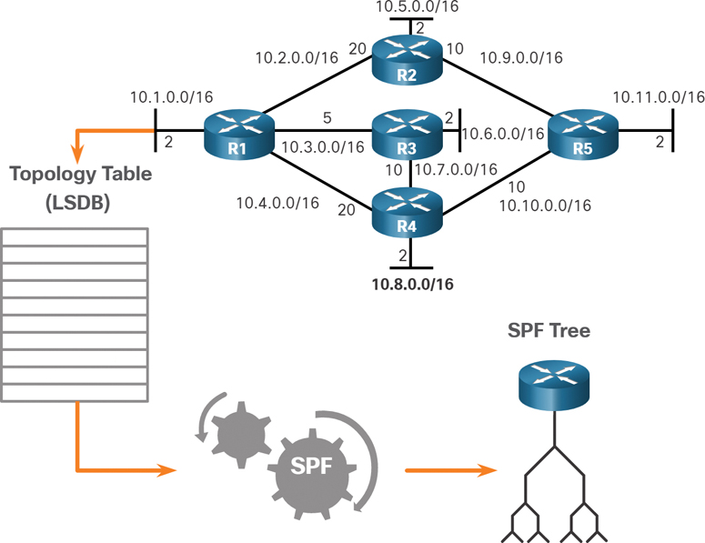
Figure 1-6 R1 Creates the SPF Tree
5. Choose the Best Route
After the SPF tree is built, the best paths to each network are offered to the IP routing table, as shown in Figure 1-7. The route is inserted into the routing table unless there is a route source to the same network with a lower administrative distance, such as a static route. Routing decisions are made based on the entries in the routing table.

Figure 1-7 Content of the R1 SPF Tree
Single-Area and Multiarea OSPF (1.1.4)
To make OSPF more efficient and scalable, OSPF supports hierarchical routing using areas. An OSPF area is a group of routers that share the same link-state information in their LSDBs. OSPF can be implemented in one of two ways:
Single-area OSPF: All routers are in one area, as shown in Figure 1-8. Best practice is to use area 0.
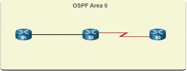
Figure 1-8 Single-Area OSPF
Multiarea OSPF: OSPF is implemented using multiple areas, in a hierarchical fashion, as shown in Figure 1-9. All areas must connect to the backbone area (area 0). Routers interconnecting the areas are referred to as area border routers (ABRs).
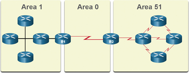
Figure 1-9 Multiarea OSPF
The focus of this chapter is on single-area OSPFv2.
Multiarea OSPF (1.1.5)
With multiarea OSPF, one large routing domain can be divided into smaller areas to support hierarchical routing. Routing still occurs between the areas (interarea routing), and many of the processor-intensive routing operations, such as recalculating the database, are kept within an area.
For instance, any change regarding the link-state information (including the addition, deletion, or modification of a link) causes the router connected to that link to send out a new LSA. Any time a router receives new information about a topology change within the area, the router must rerun the SPF algorithm, create a new SPF tree, and update the routing table. The SPF algorithm is CPU intensive, and the time it takes for calculation depends on the size of the area.
Note
Routers in other areas receive updates regarding topology changes, but these routers only update the routing table; they do not rerun the SPF algorithm.
Too many routers in one area would make the LSDBs very large and increase the load on the CPU. Therefore, arranging routers into areas effectively partitions a potentially large database into smaller and more manageable databases.
The hierarchical topology design options with multiarea OSPF can offer the following advantages:
Smaller routing tables: Tables are smaller because there are fewer routing table entries. This is because network addresses can be summarized between areas. Route summarization is not enabled by default.
Reduced link-state update overhead: Designing multiarea OSPF with smaller areas minimizes processing and memory requirements.
Reduced frequency of SPF calculations: Multiarea OSPF localize the impact of a topology change within an area. For instance, it minimizes routing update impact because LSA flooding stops at the area boundary.
For example, in Figure 1-10, R2 is an ABR for area 51. A topology change in area 51 would cause all area 51 routers to rerun the SPF algorithm, create a new SPF tree, and update their IP routing tables. The ABR, R2, would send an LSA to routers in area 0, which would eventually be flooded to all routers in the OSPF routing domain. This type of LSA does not cause routers in other areas to rerun the SPF algorithm. They only have to update their LSDB and routing table.
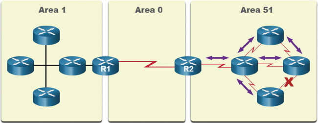
Figure 1-10 Link Change Impacts Local Area Only
Note the following in Figure 1-10:
Link failure affects the local area only (area 51).
The ABR (R2) isolates the flooding of a specific LSA to area 51.
Routers in areas 0 and 1 do not need to run the SPF algorithm.
OSPFv3 (1.1.6)
OSPFv3 is the version of OSPF used for exchanging IPv6 prefixes. Recall that in IPv6, the network address is referred to as the prefix, and the subnet mask is called the prefix length.
Similar to its IPv4 counterpart, OSPFv3 exchanges routing information to populate the IPv6 routing table with remote prefixes.
Note
With the OSPFv3 address families feature, OSPFv3 includes support for both IPv4 and IPv6. The OSPF address families feature is beyond the scope of this book.
OSPFv2 runs over the IPv4 network layer, communicating with other OSPF IPv4 peers and advertising only IPv4 routes.
OSPFv3 has the same functionality as OSPFv2 but uses IPv6 as the network layer transport, communicating with OSPFv3 peers and advertising IPv6 routes. OSPFv3 also uses the SPF algorithm as the computation engine to determine the best paths throughout the routing domain.
OSPFv3 has separate processes from its IPv4 counterpart. The processes and operations are basically the same as in the IPv4 routing protocol, but they run independently. OSPFv2 and OSPFv3 each have separate adjacency tables, OSPF topology tables, and IP routing tables.
The OSPFv3 configuration and verification commands are similar to those used in OSPFv2.
Figure 1-11 summarizes the similarities of OSPFv2 and OSPFv3.
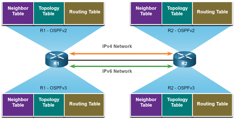
Figure 1-11 OSPFv2 and OSPFv3 Data Structures
Check Your Understanding—OSPF Features and Characteristics (1.1.7)

Refer to the online course to complete this activity.
OSPF Packets (1.2)
In this section you will learn about the types of packets used to establish and maintain an OSPF neighbor relationship.
Video—OSPF Packets (1.2.1)

Refer to the online course to view this video.
Types of OSPF Packets (1.2.2)
OSPF uses link-state packets to determine the fastest available route for a packet. OSPF uses the following link-state packets (LSPs) to establish and maintain neighbor adjacencies and exchange routing updates. Each packet serves a specific purpose in the OSPF routing process:
Type 1: Hello packet: This packet is used to establish and maintain adjacency with other OSPF routers.
Type 2: Database Description (DBD) packet: This packet contains an abbreviated list of the LSDB of the sending router and is used by receiving routers to check against the local LSDB. The LSDB must be identical on all link-state routers within an area to construct an accurate SPF tree.
Type 3: Link-State Request (LSR) packet: Receiving routers can request more information about any entry in the DBD by sending an LSR.
Type 4: Link-State Update (LSU) packet: This packet is used to reply to LSRs and to announce new information. LSUs contain several different types of LSAs.
Type 5: Link-State Acknowledgment (LSAck) packet: When an LSU is received, the router sends an LSAck to confirm receipt of the LSU. The LSAck data field is empty.
Table 1-2 summarizes the five different types of LSPs used by OSPFv2. OSPFv3 has similar packet types.
Table 1-2 OSPF Packet Types
Type |
Packet Name |
Description |
1 |
Hello |
Discovers neighbors and builds adjacencies between them. |
2 |
Database Description (DBD) |
Checks for database synchronization between routers. |
3 |
Link-State Request (LSR) |
Requests specific link-state records from router to router. |
4 |
Link-State Update (LSU) |
Sends specifically requested link-state records. |
5 |
Link-State Acknowledgment (LSAck) |
Acknowledges the other packet types. |
Link-State Updates (1.2.3)
Routers initially exchange Type 2 DBD packets. A DBD packet is an abbreviated list of the LSDB of the sending router. It is used by receiving routers to check against the local LSDB.
The receiving routers use a Type 3 LSR packet to request more information about an entry in the DBD.
The Type 4 LSU packet is used to reply to an LSR packet.
A Type 5 packet is used to acknowledge the receipt of a Type 4 LSU.
LSUs are also used to forward OSPF routing updates, such as link changes. Specifically, an LSU packet can contain 11 different types of OSPFv2 LSAs; some of the most common OSPFv2 LSAs are shown in Figure 1-12. OSPFv3 renamed several of these LSAs and also contains two additional LSAs.
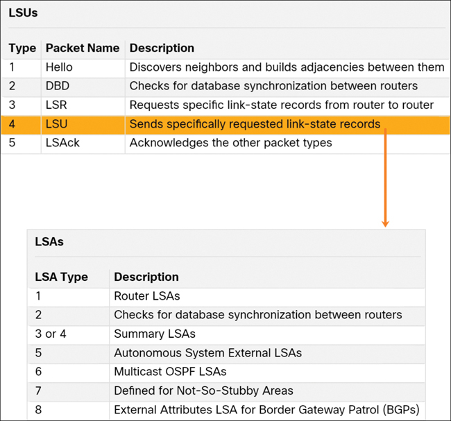
Figure 1-12 LSUs Contain LSAs
Note
The difference between the LSU and LSA terms can sometimes be confusing because these terms are often used interchangeably. However, an LSU contains one or more LSAs.
Note the following in Figure 1-12:
An LSU contains one or more LSAs.
LSAs contain route information for destination networks.
Hello Packet (1.2.4)
The OSPF Type 1 packet is the Hello packet. Hello packets are used to do the following:
Discover OSPF neighbors and establish neighbor adjacencies.
Advertise parameters on which two routers must agree to become neighbors.
Elect the designated router (DR) and backup designated router (BDR) on multiaccess networks such as Ethernet networks. Point-to-point links do not require DR or BDR.
Figure 1-13 displays the fields contained in the OSPFv2 Type 1 Hello packet.
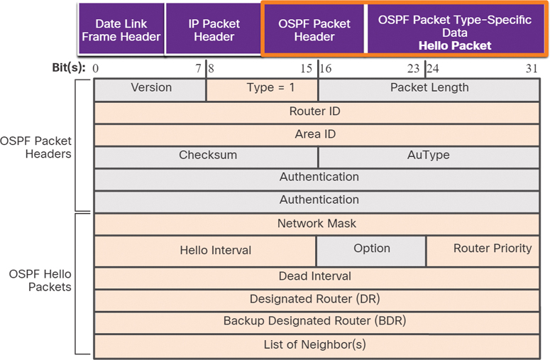
Figure 1-13 OSPF Hello Packet Content
Important fields shown in the figure include the following:
Type: This identifies the type of packet. The value 1 indicates a Hello packet. The value 2 identifies a DBD packet, 3 an LSR packet, 4 an LSU packet, and 5 an LSAck packet.
Router ID: A 32-bit value expressed in dotted decimal notation (like an IPv4 address) is used to uniquely identify the originating router.
Area ID: This is the number of the area from which the packet originated.
Network Mask: This is the subnet mask associated with the sending interface.
Hello Interval: This specifies the frequency, in seconds, at which a router sends Hello packets. The default Hello interval on multiaccess networks is 10 seconds. This timer must be the same on neighboring routers; otherwise, an adjacency is not established.
Router Priority: This is used in a DR/BDR election. The default priority for all OSPF routers is 1, but it can be manually altered to a value from 0 to 255. The higher the value, the more likely the router is to become the DR on the link.
Dead Interval: This is the time, in seconds, that a router waits to hear from a neighbor before declaring the neighboring router out of service. By default, the router Dead Interval is four times the Hello Interval. This timer must be the same on neighboring routers; otherwise, an adjacency is not established.
Designated Router (DR): This is the router ID of the DR.
Backup Designated Router (BDR): This is the router ID of the BDR.
List of Neighbors: This list identifies the router IDs of all adjacent routers.
Check Your Understanding—OSPF Packets (1.2.5)
Refer to the online course to complete this activity.
OSPF Operation (1.3)
In this section you will learn how OSPF achieves convergence.
Video—OSPF Operation (1.3.1)
Refer to the online course to view this video.
OSPF Operational States (1.3.2)
Now that you know about the OSPF link-state packets, this section explains how they work with OSPF-enabled routers. When an OSPF router is initially connected to a network, it attempts to:
Create adjacencies with neighbors
Exchange routing information
Calculate the best routes
Reach convergence
Table 1-3 details the states OSPF progresses through while attempting to reach convergence:
Table 1-3 Description of OSPF Operational States
State |
Description |
Down state |
|
Init state |
|
Two-Way state |
|
ExStart state |
|
|
|
|
|
Full state |
|
Establish Neighbor Adjacencies (1.3.3)
When OSPF is enabled on an interface, the router must determine if there is another OSPF neighbor on the link. To accomplish this, the router sends a Hello packet that contains its router ID out all OSPF-enabled interfaces. The Hello packet is sent to the reserved All OSPF Routers IPv4 multicast address 224.0.0.5. Only OSPFv2 routers process these packets. The OSPF router ID is used by the OSPF process to uniquely identify each router in the OSPF area. A router ID is a 32-bit number formatted like an IPv4 address and assigned to uniquely identify a router among OSPF peers.
When a neighboring OSPF-enabled router receives a Hello packet with a router ID that is not within its neighbor list, the receiving router attempts to establish an adjacency with the initiating router.
1. Down State to Init State
When OSPFv2 is enabled, the enabled Gigabit Ethernet 0/0 interface transitions from the Down state to the Init state, as shown in Figure 1-14. R1 starts sending Hello packets out all OSPF-enabled interfaces to discover OSPF neighbors to develop adjacencies with.
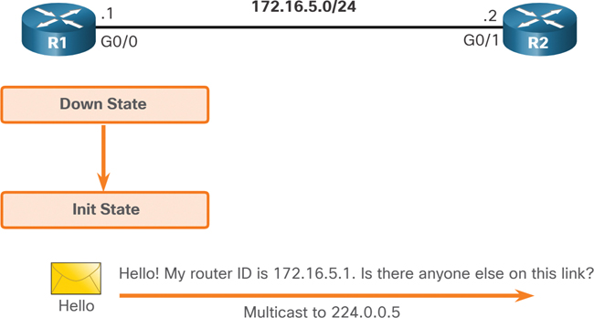
Figure 1-14 Down State to Init State
2. The Init State
R2 receives the Hello packet from R1 and adds the R1 router ID to its neighbor list. R2 then sends a Hello packet to R1, as shown in Figure 1-15. The packet contains the R2 router ID and the R1 router ID in its list of neighbors on the same interface.
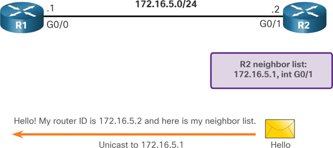
Figure 1-15 The Init State
3. Two-Way State
R1 receives the Hello packet and adds the R2 router ID to its list of OSPF neighbors, as shown in Figure 1-16. It also notices its own router ID in the list of neighbors of the Hello packet. When a router receives a Hello packet with its router ID listed in the list of neighbors, the router transitions from the Init state to the Two-Way state.

Figure 1-16 Two-Way State
The action performed in Two-Way state depends on the type of interconnection between the adjacent routers, as follows:
If the two adjacent neighbors are interconnected over a point-to-point link, they immediately transition from the Two-Way state to the ExStart state.
If the routers are interconnected over a common Ethernet network, then a designated router DR and a BDR must be elected.
4. Elect the DR and BDR
Because R1 and R2 are interconnected over an Ethernet network, a DR and BDR election takes place. As shown in Figure 1-17, R2 becomes the DR, and R1 is the BDR. This process occurs only on multiaccess networks such as Ethernet LANs.
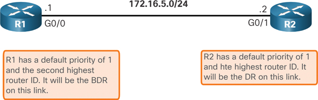
Figure 1-17 Elect the DR and BDR
Hello packets are continually exchanged to maintain router information.
Synchronizing OSPF Databases (1.3.4)
After the Two-Way state, routers transition to database synchronization states. The Hello packet was used to establish neighbor adjacencies, and the other four types of OSPF packets are used during the process of exchanging and synchronizing LSDBs. This is a three-step process:
Step 1. Decide which is the first router.
Step 2. Exchange DBDs.
Step 3. Send an LSR.
1. Decide First Router
In the ExStart state, the two routers decide which router will send the DBD packets first. The router with the higher router ID will be the first router to send DBD packets during the Exchange state. In Figure 1-18, R2 has the higher router ID and sends its DBD packets first.
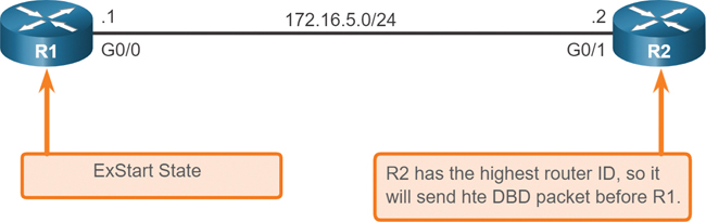
Figure 1-18 Decide Which Router Sends the First DBD
2. Exchange DBDs
In the Exchange state, the two routers exchange one or more DBD packets. A DBD packet includes information about the LSA entry header that appears in the LSDB of the router. The entries can be about a link or about a network. Each LSA entry header includes information about the link-state type, the address of the advertising router, the cost of the link, and the sequence number. The router uses the sequence number to determine the newness of the received link-state information.
In Figure 1-19, R2 sends a DBD packet to R1. When R1 receives the DBD, it performs the following actions:
Step 1. It acknowledges the receipt of the DBD using the LSAck packet.
Step 2. R1 then sends DBD packets to R2.
Step 3. R2 acknowledges R1.
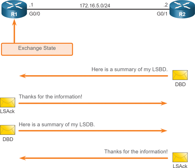
Figure 1-19 Exchange DBD Packets
3. Send an LSR
R1 compares the information received with the information it has in its own LSDB. If the DBD packet has a more current link-state entry, the router transitions to the Loading state.
For example, in Figure 1-20, R1 sends an LSR regarding network 172.16.6.0 to R2. R2 responds with the complete information about 172.16.6.0 in an LSU packet. Again, when R1 receives an LSU, it sends an LSAck. R1 then adds the new link-state entries into its LSDB.
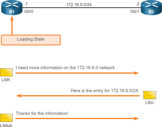
Figure 1-20 Getting Additional Route Information
After all LSRs have been satisfied for a given router, the adjacent routers are considered synchronized and in a Full state. Updates (LSUs) are sent only to neighbors in the following conditions:
When a change is perceived (incremental updates)
Every 30 minutes
The Need for a DR (1.3.5)
Why is a DR and BDR election necessary?
Multiaccess networks can create two challenges for OSPF regarding the flooding of LSAs:
Creation of multiple adjacencies: Ethernet networks could potentially interconnect many OSPF routers over a common link. Creating adjacencies with every router is unnecessary and undesirable. It would lead to an excessive number of LSAs exchanged between routers on the same network.
Extensive flooding of LSAs: Link-state routers flood their LSAs any time OSPF is initialized or when there is a change in the topology. This flooding can become excessive.
To understand the problem with multiple adjacencies, we must study a formula: For any number of routers (designated as n) on a multiaccess network, there are n (n – 1) / 2 adjacencies. For example, Figure 1-21 shows a simple topology of five routers, all of which are attached to the same multiaccess Ethernet network.

Figure 1-21 Creating Adjacencies with Every Neighbor
Without some type of mechanism to reduce the number of adjacencies, collectively these routers would form 10 adjacencies: 5 (5 – 1) / 2 = 10. This may not seem like much, but as routers are added to the network, the number of adjacencies increases dramatically. For example, a multiaccess network with 20 routers would create 190 adjacencies.
LSA Flooding with a DR (1.3.6)
A dramatic increase in the number of routers also dramatically increases the number of LSAs exchanged between the routers. This flooding of LSAs significantly impacts the operation of OSPF.
Flooding LSAs
To understand the problem of extensive flooding of LSAs, refer to Figure 1-22.
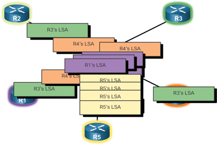
Figure 1-22 Flooding LSAs
In the figure, R2 sends out an LSA, which triggers every other router to also send out an LSA. Not shown in the figure are the required acknowledgments sent for every LSA received. If every router in a multiaccess network had to flood and acknowledge all received LSAs to all other routers on that same multiaccess network, the network traffic would become quite chaotic.
LSAs and DR
The solution to managing the number of adjacencies and the flooding of LSAs on a multiaccess network is the designated router (DR). On multiaccess networks, OSPF elects a DR to be the collection and distribution point for LSAs sent and received. A backup designated router (BDR) is also elected in case the DR fails. All other routers become DROTHERs. A DROTHER is a router that is neither the DR nor the BDR.
Note
The DR is only used for the dissemination of LSAs. The router will still use the best next-hop router indicated in the routing table for the forwarding of all other packets.
Figure 1-23 shows the role of the DR to be the collector and distributer of LSAs in a multiaccess network.
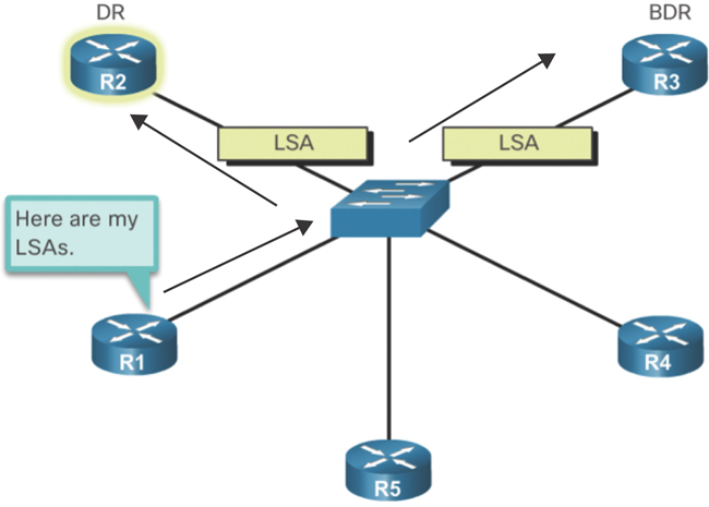
Figure 1-23 R1 Sends LSAs to the DR and BDR
Check Your Understanding—OSPF Operation (1.3.7)
Refer to the online course to complete this activity.
Summary (1.4)
The following is a summary of the sections in this chapter.
OSPF Features and Characteristics
Open Shortest Path First (OSPF) is a link-state routing protocol that was developed as an alternative for the distance vector protocol Routing Information Protocol (RIP). OSPF has significant advantages over RIP in that it offers faster convergence and scales to much larger network implementations. OSPF is a link-state routing protocol that uses the concept of areas for scalability. A link is an interface on a router. A link is also a network segment that connects two routers, or a stub network such as an Ethernet LAN that is connected to a single router. Link-state information includes the network prefix, prefix length, and cost. All routing protocols use routing protocol messages to exchange route information. The messages help build data structures, which are then processed using a routing algorithm. Routers running OSPF exchange messages to convey routing information using five types of packets: the Hello packet, the Database Description packet, the Link-State Request packet, the Link-State Update packet, and the Link-State Acknowledgment packet. OSPF messages are used to create and maintain three OSPF databases: the adjacency database creates the neighbor table, the link-state database (LSDB) creates the topology table, and the forwarding database creates the routing table. The router builds the topology table using results of calculations based on Dijkstra’s SPF (shortest-path first) algorithm. The SPF algorithm is based on the cumulative cost to reach a destination. In OSPF, cost is used to determine the best path to the destination. To maintain routing information, OSPF routers complete a generic link-state routing process to reach a state of convergence:
Step 1. Establish neighbor adjacencies.
Step 2. Exchange link-state advertisements.
Step 3. Build the link-state database.
Step 4. Execute the SPF algorithm.
Step 5. Choose the best route.
With single-area OSPF, any number can be used for the area, but best practice is to use area 0. Single-area OSPF is useful in small networks with few routers. With multi-area OSPF, one large routing domain can be divided into smaller areas to support hierarchical routing. Routing still occurs between the areas (interarea routing), and many of the processor-intensive routing operations, such as recalculating the database, are kept within an area. OSPFv3 is the OSPFv2 equivalent for exchanging IPv6 prefixes. Recall that in IPv6, the network address is referred to as the prefix, and the subnet mask is called the prefix length.
OSPF Packets
OSPF uses the following link-state packets (LSPs) to establish and maintain neighbor adjacencies and exchange routing updates: Hello (Type 1), DBD (Type 2), LSR (Type 3), LSU (Type 4), and LSAck (Type 5). LSUs are also used to forward OSPF routing updates, such as link changes. Hello packets are used to:
Discover OSPF neighbors and establish neighbor adjacencies.
Advertise parameters on which two routers must agree to become neighbors.
Elect the designated router (DR) and backup designated router (BDR) on multi-access networks like Ethernet networks. Point-to-point links do not require a DR or BDR.
Some important fields in the Hello packet are Type, Router ID, Area ID, Network Mask, Hello Interval, Router Priority, Dead Interval, DR, BDR, and List of Neighbors.
OSPF Operation
When an OSPF router is initially connected to a network, it attempts to:
Create adjacencies with neighbors
Exchange routing information
Calculate the best routes
Reach convergence
The states that OSPF progresses through to do this are Down state, Init state, Two-Way state, ExStart state, Exchange state, Loading state, and Full state. When OSPF is enabled on an interface, the router must determine if there is another OSPF neighbor on the link by sending a Hello packet that contains its router ID out all OSPF-enabled interfaces. The Hello packet is sent to the reserved All OSPF Routers IPv4 multicast address 224.0.0.5. Only OSPFv2 routers process these packets. When a neighboring OSPF-enabled router receives a Hello packet with a router ID that is not within its neighbor list, the receiving router attempts to establish an adjacency with the initiating router. After the Two-Way state, routers transition to database synchronization states, which is a three-step process:
Step 1. Decide which is the first router.
Step 2. Exchange DBDs.
Step 3. Send an LSR.
Multiaccess networks can create two challenges for OSPF regarding the flooding of LSAs: the creation of multiple adjacencies and extensive flooding of LSAs. A dramatic increase in the number of routers also dramatically increases the number of LSAs exchanged between the routers. This flooding of LSAs significantly impacts the operation of OSPF. If every router in a multiaccess network had to flood and acknowledge all received LSAs to all other routers on that same multiaccess network, the network traffic would become quite chaotic. This is why DR and BDR election is necessary. On multiaccess networks, OSPF elects a DR to be the collection and distribution point for LSAs sent and received. A BDR is also elected in case the DR fails.
Practice
There are no labs or Packet Tracer activities for this chapter.
Check Your Understanding
Complete all the review questions listed here to test your understanding of the topics and concepts in this chapter. The appendix “Answers to the ‘Check Your Understanding’ Questions” lists the answers.
1. Which OSPF data structure is identical in all routers in an OSPF area after convergence?
Adjacency database
Link-state database
Routing table
SPF tree
2. Which statements describe features of the OSPF topology table? (Choose three.)
After convergence, the table contains only the lowest-cost route entries for all known networks.
All routers in an area have identical topology tables.
It is a link-state database that represents the network topology.
Its contents are the result of running the SPF algorithm.
The table can be viewed via the show ip ospf database command.
The topology table contains information on how and where to send packets to other routers.
3. What is used to create the OSPF neighbor table?
Adjacency database
Link-state database
Forwarding database
Routing table
4. What is a function of OSPF Hello packets?
To discover neighbors and build adjacencies between them
To ensure database synchronization between routers
To request specific link-state records from neighbor routers
To send specifically requested link-state records
5. Which OPSF packet contains one or more link-state advertisements?
Hello
DBD
LSAck
LSR
LSU
6. What are the purposes of an OSPF router ID? (Choose two.)
To enable the SPF algorithm to determine the lowest-cost path to remote networks
To facilitate router participation in the election of the designated router
To facilitate the establishment of network convergence
To facilitate the transition of the OSPF neighbor state to Full
To uniquely identify the router within the OSPF domain
7. Which statement describes a multiarea OSPF network?
It consists of multiple network areas that are daisy-chained together.
It has a core backbone area with other areas connected to the backbone area.
It has multiple routers that run multiple routing protocols simultaneously, and each protocol consists of an area.
It requires a three-layer hierarchical network design approach.
8. What are the advantages of using multiarea OSPF? (Choose two.)
A backbone area is not required.
It allows OSPFv2 and OSPFv3 to run together.
It enables multiple routing protocols to run in a large network.
It improves routing efficiency by reducing the routing table and link-state update overhead.
It improves routing performance by dividing the neighbor table into separate smaller ones.
Topology changes in one area do not cause SPF recalculations in other areas.
9. Which command can be used to verify the contents of the LSDB in an OSPF area?
show ip ospf database
show ip ospf interface
show ip ospf neighbor
show ip route ospf
10. Which of the following facilitates hierarchical routing in OSPF?
Auto-summarization
Frequent SPF calculations
The election of designated routers
The use of multiple areas
11. Which step does an OSPF-enabled router take immediately after the OSPF router builds the topology table?
Chooses the best path
Establishes an adjacency with another router
Exchanges link-state advertisements
Executes the SPF algorithm
12. Which type of OSPFv2 packet contains an abbreviated list of the LSDB of a sending router and is used by receiving routers to check against the local LSDB?
Database Description
Link-State Acknowledgment
Link-State Request
Link-State Update
13. Which OSPF states are performed prior to two routers forming a neighbor adjacency? (Choose three.)
Down
Exchange
ExStart
Init
Loading
Two-Way
14. In an OSPF network, when are DR and BDR elections required?
When all the routers in an OSPF area cannot form adjacencies
When the routers are interconnected over a common Ethernet network
When the two adjacent neighbors are in two different networks
When the two adjacent neighbors are interconnected over a point-to-point link
15. When an OSPF network is converged and no network topology change has been detected by a router, how often are LSU packets sent to neighboring routers?
Every 10 seconds
Every 40 seconds
Every 15 minutes
Every 30 minutes