Chapter 11
Network Design
Objectives
Upon completion of this chapter, you will be able to answer the following questions:
How are data, voice, and video converged in a switched network?
What considerations are involved in designing a scalable network?
How do switch hardware features support network requirements?
What types of routers are available for small to medium-sized business networks?
Key Terms
This chapter uses the following key terms. You can find the definitions in the Glossary.
mission-critical services page 455
network operations center (NOC) page 457
Cisco Borderless Networks architecture page 458
three-layer hierarchical model page 460
distribution layer switch page 461
collapsed core network design page 464
building switch block page 474
departmental switch block page 474
service provider switch page 479
virtual networking switch page 479
fixed configuration switch page 480
modular configuration switch page 480
stackable configuration switch page 481
small form-factor pluggable (SFP) page 482
Power over Ethernet (PoE) page 484
Introduction (11.0)
You are a sought-after spaceship designer, and you have been asked to design a new spaceship. Your first questions are, “What will this ship be used for? How large is the crew? Will it be a war ship? Or a cargo ship? Or a science and exploration vessel?” What if you learn that the crew can be as few as 50 people, but the spaceship must be able to hold as many as 500 people, and the ship will be used in a variety of ways? How do you design a ship like this? You must design the size and configuration of the ship and the power it requires wisely.
Designing a network to meet current requirements and to adapt to future requirements is a complex task. But it can be done, thanks to hierarchical and scalable network designs that use the right components. You know you want to learn about this. Even if you have not designed your current network, knowing about network design will increase your value to the organization as a great network administrator—and who doesn’t want that?
Hierarchical Networks (11.1)
Networks must be scalable, which means they must be able to accommodate increases and decreases in size. This section looks at how the hierarchical design model is used to help accomplish this task.
Video—Three-Layer Network Design (11.1.1)

Refer to the online course to view this video.
The Need to Scale the Network (11.1.2)
Our digital world is changing. The ability to access the internet and the corporate network is no longer confined to physical offices, geographic locations, or time zones. In today’s globalized workplace, employees can access resources from anywhere in the world, and information must be available at any time, and on any device. These requirements drive the need to build next-generation networks that are secure, reliable, and highly available. These next-generation networks must not only support current expectations and equipment but must also be able to integrate legacy platforms.
Businesses increasingly rely on their network infrastructure to provide mission-critical services. As businesses grow and evolve, they hire more employees, open branch offices, and expand into global markets. These changes directly affect the requirements of a network, which must be able to scale to meet the needs of business. For example, the company in Figure 11-1 has a single location with one connection to the internet.
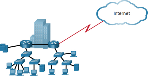
Figure 11-1 A Small, Single-Location Company
Figure 11-2 shows the company after it has grown to have multiple locations in the same city.

Figure 11-2 Company with Multiple Locations
Figure 11-3 shows the company continuing to grow and expanding to more cities. It also hires and connects teleworkers.

Figure 11-3 Enterprise Grows to Multiple Cities and Adds Teleworkers
Figure 11-4 shows the company expanding to other countries and centralizing management in a network operations center (NOC).
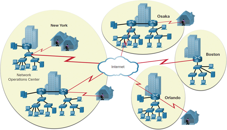
Figure 11-4 Enterprise Becomes Global and Centralizes Network Operations
A network must support the exchange of various types of network traffic—including data files, email, IP telephony, and video applications—for multiple business units. All enterprise networks must be able to do the following:
Support critical applications
Support converged network traffic
Support diverse business needs
Provide centralized administrative control
The LAN is the networking infrastructure that provides access to network communication services and resources for end users and devices. The end users and devices may be spread over a single floor or building. You create a campus network by interconnecting a group of LANs that are spread over a small geographic area. Campus network designs include small networks that use a single LAN switch up to very large networks with thousands of connections.
Borderless Switched Networks (11.1.3)
With the increasing demands of the converged network, a network must be developed with an architectural approach that embeds intelligence, simplifies operations, and is scalable to meet future demands. One recent development in network design is the Cisco Borderless Networks architecture, a network architecture that combines innovation and design. It allows organizations to support a borderless network that can connect anyone, anywhere, anytime, on any device—and do it securely, reliably, and seamlessly. This architecture is designed to address IT and business challenges such as supporting the converged network and changing work patterns.
The Cisco Borderless Networks architecture provides the framework to unify wired and wireless access—including policy, access control, and performance management—across many different device types. Using this architecture, the Borderless Networks architecture, shown in Figure 11-5, is built on a hierarchical infrastructure of hardware that is scalable and resilient.
By combining this hardware infrastructure with policy-based software solutions, the Cisco Borderless Networks architecture provides two primary sets of services—network services and user and endpoint services—under the umbrella of an integrated management solution. It enables different network elements to work together and allows users to access resources from any place, at any time, while providing optimization, scalability, and security.

Figure 11-5 Borderless Switch Network Example
Hierarchy in the Borderless Switched Network (11.1.4)
Creating a borderless switched network requires that sound network design principles be used to ensure maximum availability, flexibility, security, and manageability. A borderless switched network must deliver on current requirements and future required services and technologies. Borderless switched network design guidelines are built on the following principles:
Hierarchical: The design facilitates understanding the role of each device at every tier; simplifies deployment, operation, and management; and reduces fault domains at every tier.
Modularity: The design allows seamless network expansion and integrated service enablement on an on-demand basis.
Resiliency: The design satisfies user expectations for keeping the network always on.
Flexibility: The design allows intelligent traffic load sharing by using all network resources.
These are not independent principles. Understanding how each principle fits in the context of the others is critical. Designing a borderless switched network in a hierarchical fashion creates a foundation that allows network designers to overlay security, mobility, and unified communication features. Two time-tested and proven hierarchical design frameworks for campus networks are the three-layer hierarchical model and the two-tier layer models.
The three critical layers within these tiered designs are the access, distribution, and core layers. Each layer can be seen as a well-defined, structured module with specific roles and functions in the campus network. Introducing modularity into the campus hierarchical design further ensures that the campus network remains resilient and flexible enough to provide critical network services. Modularity also helps enable growth and allows for changes to occur over time.
Three-Tier Model
Figure 11-6 shows an example of the three-tier model.
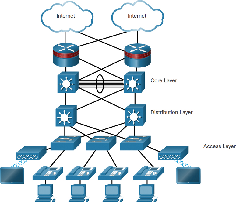
Figure 11-6 Three-Tier Model Example
At the top are two clouds depicting the internet. There are redundant links connecting to two firewall routers. The routers have redundant links to two core layer multilayer switches. There is an EtherChannel between the switches, with four links. The switches also have redundant links to two distribution layer multilayer switches. The distribution layer switches have redundant links to three access layer switches. Two of the switches have links to access points. Both access points have connections to tablets. The access layer switches are also connected to IP phones and PCs.
Two-Tier Model
Figure 11-7 shows an example of the two-tier model.

Figure 11-7 Two-Tier Model Example
At the top are two clouds depicting the internet. There are redundant links connecting to two firewall routers. The routers have redundant links to two core/distribution layer multilayer switches. The core/distribution layer switches have redundant links to three access layer switches. Two of the switches have links to access points. Both access points have connections to tablets. The access layer switches are also connected to IP phones and PCs.
Access, Distribution, and Core Layer Functions (11.1.5)
The access, distribution, and core layers perform specific functions in a hierarchical network design.
Access Layer
The access layer represents the network edge, where traffic enters or exits the campus network. Traditionally, the primary function of an access layer switch has been to provide network access to the user. Access layer switches connect to distribution layer switches, which implement network foundation technologies such as routing, quality of service, and security.
To meet network application and end-user demand, the next-generation switching platforms now provide more converged, integrated, and intelligent services to various types of endpoints at the network edge. Building intelligence into access layer switches allows applications to operate on the network more efficiently and securely.
Distribution Layer
The distribution layer interfaces between the access layer and the core layer to provide many important functions, including the following:
Aggregating large-scale wiring closet networks
Aggregating Layer 2 broadcast domains and Layer 3 routing boundaries
Providing intelligent switching, routing, and network access policy functions to access the rest of the network
Providing high availability through redundant distribution layer switches to the end user and equal-cost paths to the core
Providing differentiated services to various classes of service applications at the edge of the network
Core Layer
The core layer is the network backbone. It connects several layers of the campus network. The core layer serves as the aggregator for all of the distribution layer devices and ties the campus together with the rest of the network. The primary purposes of the core layer are to provide fault isolation and high-speed backbone connectivity.
Three-Tier and Two-Tier Examples (11.1.6)
The following sections provide three-tier and two-tier design examples and explanations.
Three-Tier Example
Figure 11-8 shows a three-tier campus network design for organizations where the access, distribution, and core are each separate layers.

Figure 11-8 Three-Tier Example
To build a simplified, scalable, cost-effective, and efficient physical cable layout design, the recommendation is to build an extended-star physical network topology from a centralized building location to all other buildings on the same campus.
The figure shows an example of the three-tier campus network design. There are six buildings, A through F. Building A is labeled Management, Building B is Marketing and Sales, Building C is Engineering, Building D is Research and Development, Building E is Information Technology, and Building F is labeled Data Center. Buildings B through F are connected to Building A in a hub-and-spoke topology. Building A is at the core layer. Building B through F are all at the distribution and access layers.
Two-Tier Example
In some cases where extensive physical or network scalability does not exist, maintaining separate distribution and core layers is not required. In smaller campus locations where there are fewer users accessing the network, or in campus sites consisting of a single building, separate core and distribution layers may not be needed. In such a scenario, the recommendation is the two-tier campus network design, also known as the collapsed core network design.
Figure 11-9 shows an example of the two-tier campus network design. The figure shows the topology of a building. A router on the edge of the network has two links: one to a WAN and another to the internet. The router has a link to a multilayer switch. The router and multilayer switch make up the collapsed core/distribution layer. The multilayer switch has links to five switches at the access layer. The access layer switches are labeled Floor 6 Research and Development, Floor 5 Engineering, Floor 4 Server Farm, Floor 3 Information Technology, and Floor 2 Management.

Figure 11-9 Two-Tier Example
Role of Switched Networks (11.1.7)
The role of switched networks has evolved dramatically in the past two decades. Not long ago, flat Layer 2 switched networks were the norm. These networks relied on Ethernet and the widespread use of hub repeaters to propagate LAN traffic throughout an organization.
As shown in Figure 11-10, networks have fundamentally changed and now tend to be switched LANs in a hierarchical design.

Figure 11-10 Switched Hierarchical Network Example
A switched LAN allows additional flexibility, traffic management, quality of service, and security. It also affords support for wireless networking and connectivity and support for other technologies, such as IP telephone and mobility services.
Check Your Understanding—Hierarchical Networks (11.1.8)

Refer to the online course to complete this activity.
Scalable Networks (11.2)
In this section, you will learn about the considerations for designing a scalable network.
Design for Scalability (11.2.1)
You understand that your network is going to change. Its number of users will likely increase, those users may be located anywhere, and they will be using a wide variety of devices. Your network must be able to change along with its users. Scalability refers to the ability of a network to grow without losing availability and reliability.
To support a large, medium, or small network, a network designer must develop a strategy to enable the network to be available and to scale effectively and easily. Included in a basic network design strategy are the following recommendations:
Use expandable, modular equipment or clustered devices that can be easily upgraded to increase capabilities. Device modules can be added to the existing equipment to support new features and devices without requiring major equipment upgrades. Some devices can be integrated into a cluster to act as one device to simplify management and configuration.
Design a hierarchical network to include modules that can be added, upgraded, and modified, as necessary, without affecting the design of the other functional areas of the network (for example, creating a separate access layer that can be expanded without affecting the distribution and core layers of the campus network).
Create an IPv4 and IPv6 addressing strategy that is hierarchical. Careful address planning eliminates the need to re-address the network to support additional users and services.
Choose routers or multilayer switches to limit broadcasts and filter other undesirable traffic from the network. Use Layer 3 devices to filter and reduce traffic to the network core.
The following sections provide more information about advanced network design requirements.
Redundant Links
Implement redundant links in a network between critical devices and between access layer and core layer devices.
Figure 11-11 illustrates redundant links between access and core layer devices. In the wiring closet there are two switches, and in the backbone there are four switches. These six switches have redundant links. The backbone switches also have redundant links to the server farm. The server farm consists of two switches and seven servers.
Multiple Links
Implement multiple links between equipment, with either link aggregation (EtherChannel) or equal-cost load balancing, to increase bandwidth. Combining multiple Ethernet links into a single, load-balanced EtherChannel configuration increases available bandwidth. EtherChannel implementations can be used when budget restrictions prohibit purchasing high-speed interfaces and fiber runs.
Figure 11-12 illustrates multiple links between switches using EtherChannel. The figure has two multilayer switches with two links each to a switch. The links are aggregated together using EtherChannel.

Figure 11-11 Redundant Links Example
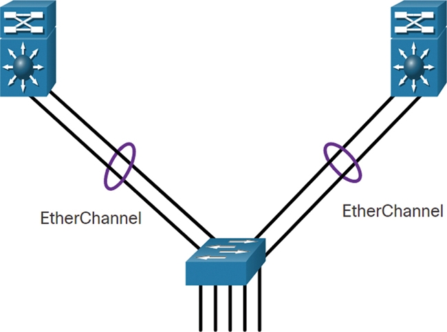
Figure 11-12 Multiple Links Example
Scalable Routing Protocol
Use a scalable routing protocol such as Open Shortest Path First (OSPF) and implement features to isolate routing updates and minimize the size of the routing table. Figure 11-13 illustrates a three-OSPF-area network consisting of Area 1, Area 0, and Area 51. Area 1 has four routers, with one labeled R1 at the edge. R1 is in both Area 1 and Area 0. Area 0 has two routers: R1 and R2. R2 is in both Area 0 and Area 51. Area 51 consists of four routers connected via serial links.

Figure 11-13 Scalable Routing Protocol Example
What if the number of routers in Area 1 and Area 51 increased to 40 routers each? OSPF provides the scalability features to support such an increase in routers.
Wireless Connectivity
Implement wireless connectivity to allow for mobility and expansion.
Figure 11-14 illustrates using wireless connectivity to allow for mobility and expansion. A router, R1, has a link to a switch, S1. S1 has redundant links to another switch, S2. S2 has links to two PCs and to a Cisco wireless access point. The Cisco wireless access point is connected wirelessly to a cellphone, a laptop, and a tablet.

Figure 11-14 Wireless Connectivity Example
Plan for Redundancy (11.2.2)
For many organizations, the availability of the network is essential to supporting business needs. Redundancy is an important part of network design. It can prevent disruption of network services by minimizing the possibility of a single point of failure. One method of implementing redundancy is by installing duplicate equipment and providing failover services for critical devices, as in the example shown in Figure 11-15.
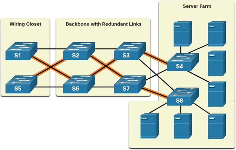
Figure 11-15 Example of a Redundant Design
Another method of implementing redundancy is by using redundant paths, as shown in the figure. Redundant paths offer alternate physical paths for data to traverse the network. Redundant paths in a switched network support high availability. However, due to the operation of switches, redundant paths in a switched Ethernet network may cause logical Layer 2 loops. For this reason, Spanning Tree Protocol (STP) is required.
STP eliminates Layer 2 loops when redundant links are used between switches. It does this by providing a mechanism for disabling redundant paths in a switched network until a path is necessary, such as when a failure occurs. STP is an open standard protocol that is used in a switched environment to create a loop-free logical topology.
Using Layer 3 in the backbone is another way to implement redundancy without the need for STP at Layer 2. Layer 3 also provides best-path selection and faster convergence during failover.
Reduce Failure Domain Size (11.2.3)
A well-designed network not only controls traffic but also limits the size of failure domains. A failure domain is the area of a network that is impacted when a critical device or network service experiences problems.
The function of the device that initially fails determines the impact of a failure domain. For example, a malfunctioning switch on a network segment normally affects only the hosts on that segment. However, if the router that connects the segment to other segments fails, the impact is much greater.
The use of redundant links and reliable enterprise-class equipment minimizes the chance of disruption in a network. Smaller failure domains reduce the impact of a failure on company productivity. They also simplify the troubleshooting process, thereby shortening the downtime for all users.
The following sections provide examples of failure domains of each associated device.
Edge Router
Figure 11-16 illustrates the failure domain of an edge router.
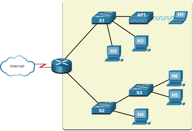
Figure 11-16 Edge Router Failure Domain
In this figure, a cloud depicting the internet is connected to an edge router. The edge router has two branched links to two switches, named S1 and S2. S1 has links to two PCs, labeled H2 and H3, and a wireless access point, labeled AP1. AP1 has a wireless connection to a laptop, labeled H1. The other switch, S2, has a link to a switch labeled S3 and a PC labeled H4. S3 has two links to two PCs, labeled H5 and H6. The failure domain for the edge router is highlighted in a square that encompasses all of the devices connected to the edge router, excluding only the link to the internet.
AP1
Figure 11-17 illustrates the failure domain of an access point, AP1.
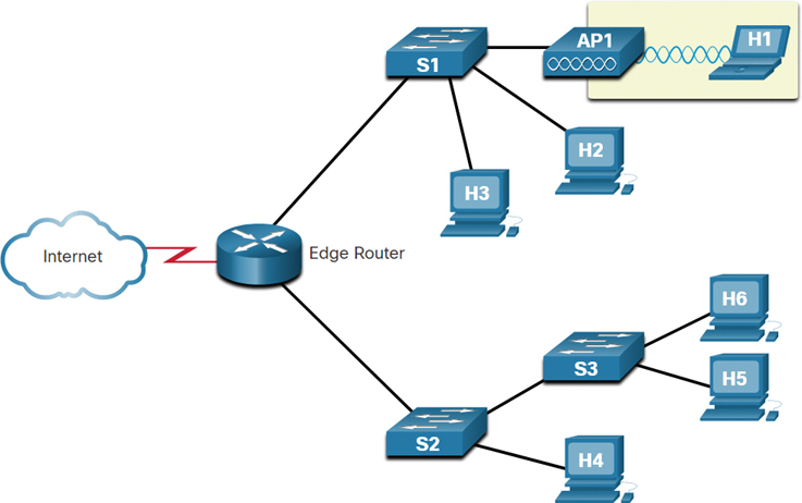
Figure 11-17 AP1 Failure Domain
In this figure, a cloud depicting the internet is connected to an edge router. The edge router has two branched links to two switches, named S1 and S2. S1 has links to two PCs, labeled H2 and H3, and a wireless access point, labeled AP1. AP1 has a wireless connection to a laptop, labeled H1. The other switch, S2, has a link to a switch labeled S3 and a PC labeled H4. S3 has two links to two PCs, labeled H5 and H6. The failure domain for AP1 consists of only the PC H1 that is wirelessly connected to AP1.
S1
Figure 11-18 illustrates the failure domain of S1.

Figure 11-18 S1 Failure Domain
In this figure, a cloud depicting the internet is connected to an edge router. The edge router has two branched links to two switches, named S1 and S2. S1 has links to two PCs, labeled H2 and H3, and a wireless access point, labeled AP1. AP1 has a wireless connection to a laptop, labeled H1. The other switch, S2, has a link to a switch labeled S3 and a PC labeled H4. S3 has two links to two PCs, labeled H5 and H6. The failure domain for S1 consists of all the devices connected to S1; the PCs H2 and H3; and AP1 and its wireless connection, H1.
S2
Figure 11-19 illustrates the failure domain of S2.
In this figure, a cloud depicting the internet is connected to an edge router. The edge router has two branched links to two switches, named S1 and S2. S1 has links to two PCs, labeled H2 and H3, and a wireless access point, labeled AP1. AP1 has a wireless connection to a laptop, labeled H1. The other switch, S2, has a link to a switch labeled S3 and a PC labeled H4. S3 has two links to two PCs, labeled H5 and H6. The failure domain for S2 consists of all the devices connected to S2; the PCs H4 and H3; and S3’s links to the PCs H5 and H6.
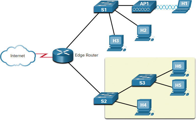
Figure 11-19 S2 Failure Domain
S3
Figure 11-20 illustrates the failure domain of S3.

Figure 11-20 S3 Failure Domain
In this figure, a cloud depicting the internet is connected to an edge router. The edge router has two branched links to two switches, named S1 and S2. S1 has links to two PCs, labeled H2 and H3, and a wireless access point, labeled AP1. AP1 has a wireless connection to a laptop, labeled H1. The other switch, S2, has a link to a switch labeled S3 and a PC labeled H4. S3 has two links to two PCs, labeled H5 and H6. The failure domain for S3 consists of all the devices connected to S3 and the PCs H5 and H6.
Limiting the Size of Failure Domains
Because a failure at the core layer of a network can have a potentially large impact, a network designer often concentrates on efforts to prevent failures. These efforts can greatly increase the cost of implementing the network. In the hierarchical design model, it is easiest and usually least expensive to control the size of a failure domain in the distribution layer. In the distribution layer, network errors can be contained to a smaller area, thus affecting fewer users. When using Layer 3 devices at the distribution layer, every router functions as a gateway for a limited number of access layer users.
Switch Block Deployment
Routers or multilayer switches are usually deployed in pairs, with access layer switches evenly divided between them. This configuration is referred to as a building switch block or a departmental switch block. Each switch block acts independently of the others. As a result, the failure of a single device does not cause the network to go down. Even the failure of an entire switch block does not affect a significant number of end users.
Increase Bandwidth (11.2.4)
In hierarchical network design, some links between access and distribution switches may need to process a greater amount of traffic than other links. As traffic from multiple links converges onto a single, outgoing link, it is possible for that link to become a bottleneck. Link aggregation, such as EtherChannel (shown in Figure 11-21), allows an administrator to increase the amount of bandwidth between devices by creating one logical link made up of several physical links.
EtherChannel uses the existing switch ports. Therefore, additional costs to upgrade the link to a faster and more expensive connection are not necessary. The EtherChannel is seen as one logical link using an EtherChannel interface. Most configuration tasks are done on the EtherChannel interface instead of on each individual port, ensuring configuration consistency throughout the links. Finally, the EtherChannel configuration takes advantage of load balancing between links that are part of the same EtherChannel, and depending on the hardware platform, one or more load-balancing methods can be implemented.

Figure 11-21 Increasing Bandwidth with EtherChannel
Expand the Access Layer (11.2.5)
The network must be designed to be able to expand network access to individuals and devices as needed. An increasingly important option for extending access layer connectivity is wireless access. Providing wireless connectivity offers many advantages, such as increased flexibility, reduced costs, and the ability to grow and adapt to changing network and business requirements.
To communicate wirelessly, an end device needs to have a wireless NIC that incorporates a radio transmitter/receiver and the required software driver to make it operational. In addition, a wireless router or a wireless access point (AP) is required for users to connect, as shown in Figure 11-22.
There are many considerations when implementing a wireless network, such as the types of wireless devices to use, wireless coverage requirements, interference considerations, and security considerations.

Figure 11-22 Adding Wireless to the Access Layer
Tune Routing Protocols (11.2.6)
Advanced routing protocols, such as Open Shortest Path First (OSPF), are used in large networks.
OSPF is a link-state routing protocol. As shown in Figure 11-23, OSPF works well for larger hierarchical networks where fast convergence is important.
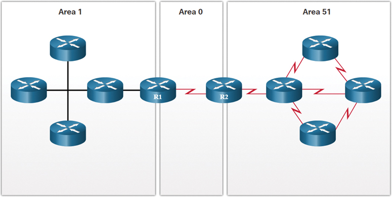
Figure 11-23 OSPF in a Large Hierarchical Network
OSPF routers establish and maintain neighbor adjacencies with other connected OSPF routers. OSPF routers synchronize their link-state database. When a network change occurs, link-state updates are sent, informing other OSPF routers of the change and establishing a new best path, if one is available.
Check Your Understanding—Scalable Networks (11.2.7)
Refer to the online course to complete this activity.
Switch Hardware (11.3)
Switches and routers are core network infrastructure devices, and selecting them may seem to be a fairly simply task. However, there are many different models of switches and routers available. Different models provide varying numbers of ports, different forwarding rates, and unique feature support.
In this section, you will learn how to select network devices based on feature compatibility and network requirement.
Switch Platforms (11.3.1)
One simple way to create hierarchical and scalable networks is to use the right equipment for the job. There are a variety of switch platforms, form factors, and other features that you should consider before choosing a switch.
When designing a network, it is important to select the proper hardware to meet current network requirements, as well as to allow for network growth. Within an enterprise network, both switches and routers play a critical role in network communication.
The following sections provide more information about the categories of switches for enterprise networks.
Campus LAN Switches
To scale network performance in an enterprise LAN, there are core, distribution, access, and compact switches. These switch platforms vary from fanless switches with eight fixed ports to 13-blade switches supporting hundreds of ports. Campus LAN switch platforms include the Cisco 2960, 3560, 3650, 3850, 4500, 6500, and 6800 Series. Figure 11-24 shows a Cisco 3650 Series switch.

Figure 11-24 Campus LAN Switches: Cisco 3650 Series
Cloud-Managed Switches
The Cisco Meraki cloud-managed switches, such as the one in Figure 11-25, enable virtual stacking of switches. They monitor and configure thousands of switch ports over the web, without the intervention of onsite IT staff.

Figure 11-25 Cloud-Managed Switches: Cisco Meraki
Data Center Switches
A data center should be built using switches that promote infrastructure scalability, operational continuity, and transport flexibility. The data center switch platforms include the Cisco Nexus Series switches, such as the 7000 Series switch shown in Figure 11-26.
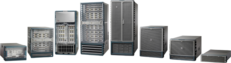
Figure 11-26 Data Center Switches: Cisco Nexus 7000 Series
Service Provider Switches
Service provider switches fall under two categories: aggregation switches and Ethernet access switches. Aggregation switches are carrier-grade Ethernet switches that aggregate traffic at the edge of a network. Service provider Ethernet access switches feature application intelligence, unified services, virtualization, integrated security, and simplified management. The Cisco ASR 9000 Series is shown in Figure 11-27.
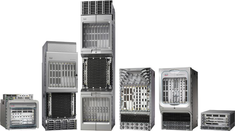
Figure 11-27 Service Provider Switches: Cisco ASR 9000 Series
Virtual Networking
Networks are becoming increasingly virtualized. Cisco Nexus virtual networking switch platforms, such as the Nexus 1000v in Figure 11-28, provide secure multi-tenant services by adding virtualization intelligence technology to the data center network.
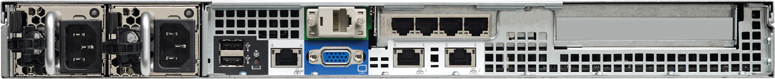
Figure 11-28 Virtual Networking: Cisco Nexus 1000v
Switch Form Factors (11.3.2)
When selecting switches, network administrators must determine the switch form factors. This includes fixed configuration, modular configuration, stackable, or non-stackable. The following sections provide more information about switch form factors.
Fixed Configuration Switches
Features and options on fixed configuration switches are limited to those that originally come with the switch. For example, the Cisco 3850 Series switches in Figure 11-29 are fixed configuration switches.

Figure 11-29 Fixed Configuration Switches: Cisco 3850 Series
Modular Configuration Switches
The chassis on modular switches accept field-replaceable line cards. The Cisco MDS 9000 Series switches in Figure 11-30 are modular configuration switches.
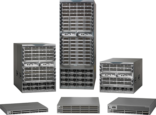
Figure 11-30 Modular Configuration Switches: Cisco MDS 9000 Series
Stackable Configuration Switches
Special cables, as shown in Figure 11-31, are used to connect stackable configuration switches that allow them to effectively operate as one large switch.
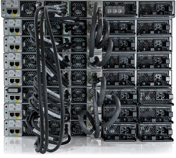
Figure 11-31 Stackable Configuration Switches
Thickness
The thickness of a switch, which is expressed in the number of rack units (RUs), is also important for switches that are mounted in a rack. For example, each of the fixed configuration Cisco 3650 Series switches shown in Figure 11-32 is one rack units (1U), or 1.75 inches (44.45 mm) in height.
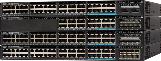
Figure 11-32 Four Switches, Each 1U Thick
Port Density (11.3.3)
The port density of a switch refers to the number of ports available on the switch. Figure 11-33 shows three different switches with different port densities.

Figure 11-33 Cisco Catalyst 3850 Switches with Different Port Densities
Fixed configuration switches support a variety of port density configurations. The Cisco Catalyst 3850 Series switches come in 12-, 24-, and 48-port configurations, as shown in Figure 11-33. The 48-port switch has an option for additional ports for small form-factor pluggable (SFP) devices.
Modular switches can support very high port densities through the addition of multiple switchport line cards. For example, the modular Catalyst 9400 switch shown in Figure 11-34 supports 384 switchport interfaces.
Large networks that support many thousands of network devices require high-density, modular switches to make the best use of space and power. Without a high-density modular switch, a network would need many fixed configuration switches to accommodate the number of devices that need network access—as well as many power outlets and a lot of closet space.
A network designer must also consider the issue of uplink bottlenecks. A series of fixed configuration switches may consume many additional ports for bandwidth aggregation between switches in order to achieve target performance. With a single modular switch, bandwidth aggregation is less of an issue because the backplane of the chassis can provide the necessary bandwidth to accommodate the devices connected to the switchport line cards.

Figure 11-34 Catalyst 9400 Switch Can Be Expanded to Provide More Ports
Forwarding Rates (11.3.4)
Forwarding rates define the processing capabilities of a switch by rating how much data a switch can process per second. Switch product lines are classified by forwarding rates. Entry-level switches have lower forwarding rates than enterprise-level switches. Forwarding rates are important to consider when selecting a switch. If the switch forwarding rate is too low, the switch cannot accommodate full wire-speed communication across all of its switch ports. Wire speed is the data rate that each Ethernet port on the switch is capable of attaining. Data rates can be 100 Mbps, 1 Gbps, 10 Gbps, or 100 Gbps.
For example, a typical 48-port Gigabit switch operating at full wire speed generates 48 Gbps of traffic. If the switch supports a forwarding rate of only 32 Gbps, it cannot run at full wire speed across all ports simultaneously. Fortunately, access layer switches typically do not need to operate at full wire speed because they are physically limited by their uplinks to the distribution layer. This means that less expensive, lower-performing switches can be used at the access layer, and more expensive, higher-performing switches can be used at the distribution and core layers, where the forwarding rate has a greater impact on network performance.
Power over Ethernet (11.3.5)
Power over Ethernet (PoE) allows a switch to deliver power to a device over the existing Ethernet cabling. This feature can be used by IP phones and some wireless access points, allowing them to be installed anywhere that there is an Ethernet cable. A network administrator should ensure that the PoE features are actually required for a given installation because switches that support PoE are expensive.
The following sections provide examples of PoE ports on different devices.
Switch
PoE ports look the same as any other switch ports. Check the model of a switch to determine whether its ports support PoE.
Figure 11-35 displays a Catalyst 3650 Layer 3 switch with 24 PoE-enabled ports.

Figure 11-35 PoE Ports on a Catalyst 3650 Layer 3 Switch
IP Phone
Figure 11-36 shows the external power source and PoE ports on the back of an IP phone.

Figure 11-36 PoE Ports on an IP Phone
WAP
PoE ports on wireless access points look the same as any other switch ports. Check the model of the wireless access point to determine if its ports support PoE.
Figure 11-37 shows a PoE port on the back of a wireless access point.
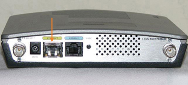
Figure 11-37 PoE Port on a WAP
Cisco Catalyst 2960-C
The Cisco Catalyst 2960-C and 3560-C Series compact switches support PoE pass-through. PoE pass-through allows a network administrator to power PoE devices that are connected to the switch, as well as the switch itself, by drawing power from certain upstream switches.
Figure 11-38 shows PoE-enabled ports on a Cisco Catalyst 2960-C switch.

Figure 11-38 PoE Ports on a Switch
Multilayer Switching (11.3.6)
Multilayer switches are typically deployed in the core and distribution layers of an organization's switched network. Multilayer switches are characterized by their ability to build a routing table, support a few routing protocols, and forward IP packets at a rate close to that of Layer 2 forwarding. Multilayer switches often support specialized hardware, such as application-specific integrated circuits (ASICs). ASICs along with dedicated software data structures can streamline the forwarding of IP packets, independently of the CPU.
There is a trend in networking toward a pure Layer 3 switched environment. When switches were first used in networks, none of them supported routing. Now, almost all switches support routing. It is likely that soon every switch will incorporate a route processor because the cost of doing so is decreasing relative to other constraints.
Figure 11-39 shows a Catalyst 2960. Catalyst 2960 switches illustrate the migration to a pure Layer 3 environment. With IOS versions prior to 15.x, these switches supported only one active switch virtual interface (SVI). With IOS 15.x, these switches now support multiple active SVIs. This means that a switch can be remotely accessed via multiple IP addresses on distinct networks.

Figure 11-39 Cisco Catalyst 2960 Series Supports Multilayer Switching
Business Considerations for Switch Selection (11.3.7)
Table 11-1 highlights some of the common business considerations when selecting switch equipment.
Table 11-1 Common Business Considerations
Consideration |
Description |
Cost |
The cost of a switch depends on the number and speed of the interfaces, supported features, and expansion capability. |
Port density |
Network switches must support the appropriate number of devices on the network. |
Power |
It is now common to power access points, IP phones, and compact switches using Power over Ethernet (PoE). In addition to PoE considerations, some chassis-based switches support redundant power supplies. |
Reliability |
A switch should provide continuous access to the network. |
Port speed |
The speed of the network connection is of primary concern to end users. |
The ability of a switch to store frames is important in a network where there may be congested ports to servers or other areas of the network. |
|
Scalability |
The number of users on a network typically grows over time; therefore, a switch should provide the opportunity for growth. |
Check Your Understanding—Switch Hardware (11.3.8)
Refer to the online course to complete this activity.
Router Hardware (11.4)
There are various types of router platforms available. Like switches, routers differ in physical configuration and form factor, in terms of the number and types of interfaces it supports, and be the features supported.
The focus of this section is on types of routers available to support network requirements in small to medium-sized business networks.
Router Requirements (11.4.1)
Switches are not the only component of a network that come with a variety of features. Your choice of router is another very important decision. Routers play a critical role in networking, connecting homes and businesses to the internet, interconnecting multiple sites within an enterprise network, providing redundant paths, and connecting ISPs on the internet. Routers can also act as translators between different media types and protocols. For example, a router can accept packets from an Ethernet network and re-encapsulate them for transport over a serial network.
A router uses the network portion (prefix) of the destination IP address to route packets to the proper destination. It selects an alternate path if a link goes down. All hosts on a local network specify the IP address of the local router interface in their IP configuration. This router interface is the default gateway. The ability to route efficiently and recover from network link failures is critical to delivering packets to their destination.
Routers also serve other beneficial functions, including the following:
They provide broadcast containment by limiting broadcasts to the local network.
They interconnect geographically separated locations.
They group users logically by application or department within a company, based on common needs or requiring access to the same resources.
They provide enhanced security, filtering unwanted traffic through access control lists.
Cisco Routers (11.4.2)
As a network grows, it is important to select the proper routers to meet its requirements. There are different categories of Cisco routers. The following sections provide more information about the categories of routers.
Branch Routers
Branch routers optimize branch services on a single platform while delivering an optimal application experience across branch and WAN infrastructures. Maximizing service availability at the branch requires networks designed for 24x7x365 uptime. Highly available branch networks must ensure fast recovery from typical faults while minimizing or eliminating the impact on service, and they must provide simple network configuration and management. Figure 11-40 shows Cisco Integrated Services Router (ISR) 4000 Series routers.
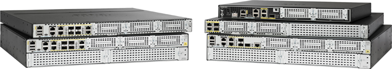
Figure 11-40 Cisco ISR 4000 Series
Network Edge Routers
Network edge routers enable the network edge to deliver high-performance, highly secure, and reliable services that unite campus, data center, and branch networks. Customers expect a high-quality media experience and more types of content than ever before. Customers want interactivity, personalization, mobility, and control for all content. Customers also want to access content anytime and anyplace they choose, over any device, whether at home, at work, or on the go. Network edge routers must deliver enhanced quality of service and nonstop video and mobile capabilities. Figure 11-41 shows Cisco Aggregation Services Routers (ASR) 9000 Series routers.
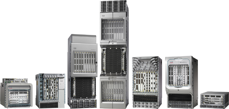
Figure 11-41 Cisco ASR 9000 Series
Service Provider Routers
Service provider routers deliver end-to-end scalable solutions and subscriber-aware services. Operators must optimize operations, reduce expenses, and improve scalability and flexibility in order to deliver next-generation internet experiences across all devices and locations. These systems are designed to simplify and enhance the operation and deployment of service-delivery networks. Figure 11-42 shows Cisco Network Convergence System (NCS) 6000 Series routers.

Figure 11-42 Cisco NCS 6000 Series
Industrial
Industrial routers are designed to provide enterprise-class features in rugged and harsh environments. Their compact, modular, ruggedized design is excellent for mission-critical applications. Figure 11-43 shows Cisco 1100 Series Industrial Integrated Services routers.

Figure 11-43 Cisco 1100 Series
Router Form Factors (11.4.3)
Like switches, routers also come in many form factors. Network administrators in an enterprise environment should be able to support a variety of routers, from small desktop routers to rack-mounted or blade models. The following sections provide more information on various Cisco router platforms.
Cisco 900 Series
Figure 11-44 shows the Cisco 921-4P, which is a small branch office router. It combines WAN, switching, security, and advanced connectivity options in a compact, fanless platform for small and medium-sized businesses.
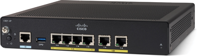
Figure 11-44 Cisco 921-4P
ASR 9000 and 1000 Series
The ASR routers in Figure 11-45 provide density and resiliency with programmability for a scalable network edge.

Figure 11-45 Cisco ASR 9000 and 1000 Series Aggregation Services Routers
5500 Series
The 5500 Series router in Figure 11-46 is designed to efficiently scale between large data centers and large enterprise networks, web, and service provider WAN and aggregation networks.

Figure 11-46 Cisco Network Convergence System 5500 Series Router
Cisco 800
The Cisco Industrial Router 829 in Figure 11-47 is compact and designed for harsh environments. It supports cellular, 2.4 GHz, and 5 GHz wireless access.

Figure 11-47 Cisco 800 Industrial Integrated Services Router
Fixed Configuration or Modular
Routers can also be categorized as fixed configuration or modular. With a fixed configuration, the desired router interfaces are built in. Modular routers come with multiple slots that allow a network administrator to change the interfaces on the router. Routers come with a variety of different interfaces, such as Fast Ethernet, Gigabit Ethernet, serial, and fiber optic.
A comprehensive list of Cisco routers can be found by searching the Cisco website, www.cisco.com.
Check Your Understanding—Router Hardware (11.4.4)
Refer to the online course to complete this activity.
Summary (11.5)
The following is a summary of the sections in this chapter.
Hierarchical Networks
All enterprise networks must support critical applications, support converged network traffic, support diverse business needs, and provide centralized administrative control. The Cisco Borderless Networks architecture provides a framework to unify wired and wireless access—including policy, access control, and performance management—across many different device types. A borderless network is built on a hierarchical infrastructure of hardware that is scalable and resilient. Two proven hierarchical design frameworks for campus networks are the three-tier layer and the two-tier layer models. The three critical layers within these tiered designs are the access, distribution, and core layers. The access layer represents the network edge, where traffic enters or exits the campus network. Access layer switches connect to distribution layer switches, which implement network foundation technologies such as routing, quality of service, and security. The distribution layer interfaces between the access layer and the core layer. The primary purpose of the core layer is to provide fault isolation and high-speed backbone connectivity. Networks have fundamentally changed to switched LANs in a hierarchical network, providing QoS, security, support for wireless connectivity, and IP telephony and mobility services.
Scalable Networks
A basic network design strategy includes the following recommendations: Use expandable, modular equipment, or clustered devices; design a hierarchical network to include modules that can be added, upgraded, and modified; create a hierarchical IPv4 and IPv6 addressing strategy; and choose routers or multilayer switches to limit broadcasts and filter other undesirable traffic from the network. Implement redundant links in the network between critical devices and between access layer and core layer devices. Implement multiple links between equipment, with either link aggregation (EtherChannel) or equal-cost load balancing to increase bandwidth. Use a scalable routing protocol and implement features within that routing protocol to isolate routing updates and minimize the size of the routing table. Implement wireless connectivity to allow for mobility and expansion. One method of implementing redundancy is to install duplicate equipment and provide failover services for critical devices. Another method of implementing redundancy is to create redundant paths. A well-designed network not only controls traffic but limits the size of failure domains. Switch blocks act independently of the others, so the failure of a single device does not cause the network to go down. Link aggregation, such as through EtherChannel, allows an administrator to increase the amount of bandwidth between devices by creating one logical link made up of several physical links. Wireless connectivity expands the access layer. When implementing a wireless network, you must consider the types of wireless devices to use, wireless coverage requirements, interference considerations, and security. Link-state routing protocols such as OSPF work well for larger hierarchical networks where fast convergence is important. OSPF routers establish and maintain neighbor adjacencies with other connected OSPF routers; they synchronize their link-state database. When a network change occurs, link-state updates are sent, informing other OSPF routers of the change and establishing a new best path.
Switch Hardware
There are several categories of switches for enterprise networks, including campus LAN, cloud-managed, data center, service provider, and virtual networking switches. Form factors for switches include fixed configuration, modular configuration, and stackable configuration. The thickness of a switch is expressed as the number of rack units. The port density of a switch refers to the number of ports available on a single switch. The forwarding rate defines the processing capabilities of a switch by rating how much data the switch can process per second. Power over Ethernet (PoE) allows a switch to deliver power to a device over the existing Ethernet cabling. Multilayer switches are typically deployed in the core and distribution layers of an organization's switched network. Multilayer switches are characterized by their ability to build a routing table, support a few routing protocols, and forward IP packets at a rate close to that of Layer 2 forwarding. Business considerations for switch selection include cost, port density, power, reliability, port speed, frame buffers, and scalability.
Router Hardware
Routers use the network portion (prefix) of the destination IP address to route packets to the proper destination. They select an alternate path if a link or path goes down. All hosts on a local network specify the IP address of the local router interface in their IP configuration. This router interface is the default gateway. Routers also serve other beneficial functions:
They provide broadcast containment by limiting broadcasts to the local network.
They interconnect geographically separate locations.
They group users logically by application or department within a company, based on common needs or requiring access to the same resources.
They provide enhanced security by filtering unwanted traffic through access control lists.
Cisco offers several categories of routers, including branch, network edge, service provider, and industrial routers. Branch routers optimize branch services on a single platform while delivering an optimal application experience across branch and WAN infrastructures. Network edge routers deliver high-performance, highly secure, and reliable services that unite campus, data center, and branch networks. Service provider routers differentiate the service portfolio and increase revenues by delivering end-to-end scalable solutions and subscriber-aware services. Industrial routers are designed to provide enterprise-class features in rugged and harsh environments. Cisco router form factors include the Cisco 900 Series, the ASR 9000 and 1000 Series, the 5500 Series, and the Cisco 800. Routers can also be categorized as fixed configuration or modular. With fixed configuration, the desired router interfaces are built in. Modular routers come with multiple slots that allow a network administrator to change the interfaces on the router. Routers come with a variety of different interfaces, such as Fast Ethernet, Gigabit Ethernet, serial, and fiber optic.
Packet Tracer—Compare Layer 2 and Layer 3 Devices (11.5.1)

In this Packet Tracer activity, you will use various commands to examine three different switching topologies and compare the similarities and differences between the 2960 and 3650 switches. You will also compare the routing table of a 4321 router with that of a 3650 switch.
Practice
The following Packet Tracer activity provides practice with the topics introduced in this chapter. The instructions are available in the companion Enterprise Networking, Security, and Automation Labs & Study Guide (CCNAv7) (ISBN 9780136634324). There are no labs for this chapter.
Packet Tracer Activity
Packet Tracer 11.5.1: Compare Layer 2 and Layer 3 Devices
Check Your Understanding Questions
Complete all the review questions listed here to test your understanding of the topics and concepts in this chapter. The appendix “Answers to the ‘Check Your Understanding’ Questions” lists the answers.
1. What is a basic function of the Cisco Borderless Networks architecture distribution layer?
Acting as a backbone
Aggregating all the campus blocks
Aggregating Layer 2 and Layer 3 routing boundaries
Providing access to end-user devices
2. What is a collapsed core in a network design?
A combination of the functionality of the access and core layers
A combination of the functionality of the access and distribution layers
A combination of the functionality of the access, distribution, and core layers
A combination of the functionality of the distribution and core layers
3. Which two previously independent technologies should a network administrator attempt to combine after choosing to upgrade to a converged network infrastructure? (Choose two.)
Electrical system
Mobile cell phone traffic
Scanners and printers
User data traffic
VoIP phone traffic
4. How is a two-tier LAN network design implemented?
The access, distribution, and core layers are collapsed into one tier to separate the backbone layer.
The access and core layers are collapsed into one tier, and the distribution layer is on a separate tier.
The access and distribution layers are collapsed into one tier, and the core layer is on a separate tier.
The distribution and core layers are collapsed into one tier, and the access layer is on a separate tier.
5. A local law firm is redesigning the company network so that all 20 employees can be connected to a LAN and to the internet. The law firm would prefer a low-cost and easy solution for the project. What type of switch should be selected?
fixed configuration
modular configuration
stackable configuration
data center switch
service provider switch
6. What is one function of a Layer 2 switch?
determining which interface is used to forward a frame, based on the destination MAC address
duplicating the electrical signal of each frame to every port
forwarding data based on logical addressing
learning the port assigned to a host by examining the destination MAC address
7. Which network device can be used to eliminate collisions on an Ethernet network?
Hub
NIC
Switch
Wireless access point
8. Which type of address does a switch use to build the MAC address table?
Destination IP address
Destination MAC address
Source IP address
Source MAC address
9. What are two reasons a network administrator would segment a network with a Layer 2 switch? (Choose two.)
To create fewer collision domains
To create more broadcast domains
To eliminate virtual circuits
To enhance user bandwidth
To isolate ARP request messages from the rest of the network
To isolate traffic between segments
10. Which statement describes the microsegmentation feature of a LAN switch?
All ports inside the switch form one collision domain.
Each port forms a collision domain.
Frame collisions are forwarded.
The switch does not forward broadcast frames.
11. A ____________________ network is one that uses the same infrastructure to carry voice, data, and video signals.
12. In the Cisco enterprise architecture, which two functional parts of the network are combined to form a collapsed core design? (Choose two.)
Access layer
Core layer
Distribution layer
Enterprise edge
Provider edge
13. Which design feature limits the impact of a distribution switch failure in an enterprise network?
The installation of redundant power supplies
The purchase of enterprise equipment that is designed for large traffic volume
The use of a collapsed core design
The use of the building switch block approach
14. What are two benefits of extending access layer connectivity to users through a wireless medium? (Choose two.)
Decreased number of critical points of failure
Increased bandwidth availability
Increased flexibility
Increased network management options
Reduced costs
15. As the network administrator, you have been asked to implement EtherChannel on the corporate network. What does this configuration involve?
Grouping multiple physical ports to increase bandwidth between two switches
Grouping two devices to share a virtual IP address
Providing redundant devices to allow traffic to flow in the event of device failure
Providing redundant links that dynamically block or forward traffic
16. Which statement describes Cisco Meraki switches?
They are campus LAN switches that perform the same functions as Cisco 2960 switches.
They are cloud-managed access switches that enable virtual stacking of switches.
They are service provider switches that aggregate traffic at the edge of the network.
They promote infrastructure scalability, operational continuity, and transport flexibility.
17. What term is used to describe the thickness or height of a switch?
Domain size
Module size
Port density
Rack unit
18. What are two functions of a router? (Choose two.)
It connects multiple IP networks.
It controls the flow of data via the use of Layer 2 addresses.
It determines the best path for sending packets.
It increases the size of the broadcast domain.
It manages the VLAN database.