Chapter 6
NAT for IPv4
Objectives
Upon completion of this chapter, you will be able to answer the following questions:
What are the purpose and function of NAT?
How do different types of NAT operate?
What are the advantages and disadvantages of NAT?
How do you configure static NAT using the CLI?
How do you configure dynamic NAT using the CLI?
How do you configure PAT using the CLI?
What is NAT for IPv6?
Key Terms
This chapter uses the following key terms. You can find the definitions in the Glossary.
Network Address Translation (NAT) page 226
inside global address page 229
outside local address page 229
outside global address page 229
Port Address Translation (PAT) page 233
Network Address Translation–Protocol Translation (NAT-PT) page 259
Introduction (6.0)
IPv4 addresses are 32-bit numbers. Mathematically, this means that there can be just over 4 billion unique IPv4 addresses. In the 1980s, this seemed like more than enough IPv4 addresses. Then came the development of affordable desktop and laptop computers, smartphones and tablets, many other digital technologies, and, of course, the internet. It rather quickly became apparent that 4 billion IPv4 addresses would not be nearly enough to handle the growing demand. This is why IPv6 was developed. However, most networks today are IPv4-only or a combination of IPv4 and IPv6. The transition to IPv6-only networks is still ongoing, and Network Address Translation (NAT) was developed to help manage the 4 billion IPv4 addresses so that we can all use our many devices to access the internet. As you can imagine, it is important that you understand the purpose of NAT and how it works. As a bonus, this chapter contains multiple Packet Tracer activities where you get to configure different types of NAT. Let’s get going!
NAT Characteristics (6.1)
Almost all networks connecting to the internet use NAT to translate IPv4 addresses. Typically, organizations assign private IP addresses to inside hosts. When communication exits the network, NAT translates those private addresses into public IP addresses. Return traffic to a public IPv4 address is re-translated to the internal private IPv4 address.
This section explains the purpose and function of NAT.
IPv4 Private Address Space (6.1.1)
As you know, there are not enough public IPv4 addresses to assign a unique address to each device connected to the internet. Networks are commonly implemented using private IPv4 addresses, as defined in RFC 1918. The RFC 1918 address classes are listed in Table 6-1. It is very likely that the computer that you use to view this course is assigned a private address.
Table 6-1 Private Internet Addresses Defined in RFC 1918
Class |
RFC 1918 Internal Address Range |
Prefix |
A |
10.0.0.0–10.255.255.255 |
10.0.0.0/8 |
B |
172.16.0.0–172.31.255.255 |
172.16.0.0/12 |
C |
192.168.0.0–192.168.255.255 |
192.168.0.0/16 |
These private addresses are used within an organization or site to allow devices to communicate locally. However, because these addresses do not identify any single company or organization, private IPv4 addresses cannot be routed over the internet. To allow a device with a private IPv4 address to access devices and resources outside the local network, the private address must first be translated to a public address.
NAT provides the translation of private addresses to public addresses, as shown in Figure 6-1. This allows a device with a private IPv4 address to access resources outside the private network, such as those found on the internet. Using NAT with private IPv4 addresses has been the primary method of preserving public IPv4 addresses. A single public IPv4 address can be shared by hundreds or even thousands of devices, each configured with a unique private IPv4 address.

Figure 6-1 NAT Router Translating Private IPv4 Addresses to Public IPv4 Address
Without NAT, the exhaustion of the IPv4 address space would have occurred well before the year 2000. However, NAT has limitations and disadvantages, which will be explored later in this chapter. The solution to the exhaustion of IPv4 address space and the limitations of NAT is the eventual transition to IPv6.
What Is NAT? (6.1.2)
NAT has many uses, but its primary use is to conserve public IPv4 addresses. It does this by allowing networks to use private IPv4 addresses internally and providing translation to a public address only when needed. NAT has a perceived benefit of adding a degree of privacy and security to a network because it hides internal IPv4 addresses from outside networks.
NAT-enabled routers can be configured with one or more valid public IPv4 addresses. These public addresses are known as the NAT pool. When an internal device sends traffic out of the network, the NAT-enabled router translates the internal IPv4 address of the device to a public address from the NAT pool. To outside devices, all traffic entering and exiting the network appears to have a public IPv4 address from the provided pool of addresses.
A NAT router typically operates at the border of a stub network. A stub network is one or more networks with a single connection to its neighboring network, with one way in and one way out of the network. In the example in Figure 6-2, R2 is a border router. From the ISP’s point of view, R2 forms a stub network.

Figure 6-2 The Role NAT Plays in a Stub Network
When a device inside a stub network wants to communicate with a device outside of its network, the packet is forwarded to the border router. The border router performs the NAT process, translating the internal private address of the device to a public outside routable address.
Note
The connection to the ISP may use a private address or a public address that is shared among customers. For the purposes of this chapter, a public address is shown.
How NAT Works (6.1.3)
In Figure 6-3, PC1 with private address 192.168.10.10 wants to communicate with an outside web server with public address 209.165.201.1.

Figure 6-3 NAT in Action
NAT Terminology (6.1.4)
In NAT terminology, the inside network is the set of networks that is subject to translation. The outside network refers to all other networks.
When using NAT, IPv4 addresses have different designations based on whether they are on the private network or on the public network (internet) and whether the traffic is incoming or outgoing.
NAT includes four types of addresses:
When determining which type of address is used, it is important to remember that NAT terminology is always applied from the perspective of the device with the translated address:
Inside address: The address of the device that is being translated by NAT
Outside address: The address of the destination device
NAT also uses the concept of local or global with respect to addresses:
Local address: Any address that appears on the inside portion of the network
Global address: Any address that appears on the outside portion of the network
The terms inside and outside are combined with the terms local and global to refer to specific addresses. The NAT router R2 in Figure 6-4 is the demarcation point between the inside and outside networks. R2 is configured with a pool of public addresses to assign to inside hosts. Refer to the network and NAT table in the figure for the following discussion of each of the NAT address types.

Figure 6-4 Topology for NAT Terminology
Inside Local
The inside local address is the address of the source as seen from inside the network. This is typically a private IPv4 address. In Figure 6-4, the IPv4 address 192.168.10.10 is assigned to PC1. This is the inside local address of PC1.
Inside Global
The inside global address is the address of the source as seen from the outside network. This is typically a globally routable IPv4 address. In Figure 6-4, when traffic from PC1 is sent to the web server at 209.165.201.1, R2 translates the inside local address to an inside global address. In this case, R2 changes the IPv4 source address from 192.168.10.10 to 209.165.200.226. In NAT terminology, the inside local address 192.168.10.10 is translated to the inside global address 209.165.200.226.
Outside Global
The outside global address is the address of the destination as seen from the outside network. It is a globally routable IPv4 address assigned to a host on the internet. For example, the web server is reachable at IPv4 address 209.165.201.1. Most often the outside local and outside global addresses are the same.
Outside Local
The outside local address is the address of the destination as seen from the inside network. In the example in Figure 6-4, PC1 sends traffic to the web server at the IPv4 address 209.165.201.1. While uncommon, this address could be different from the globally routable address of the destination.
PC1 has inside local address 192.168.10.10. From the perspective of PC1, the web server has outside address 209.165.201.1. When packets are sent from PC1 to the global address of the web server, the inside local address of PC1 is translated to 209.165.200.226 (inside global address). The address of the outside device is not typically translated because that address is usually a public IPv4 address.
Notice that PC1 has different local and global addresses, whereas the web server has the same public IPv4 address for both. From the perspective of the web server, traffic originating from PC1 appears to have come from 209.165.200.226, the inside global address.
Check Your Understanding—NAT Characteristics (6.1.5)

Refer to the online course to complete this activity.
Types of NAT (6.2)
In this section, you will learn about the operation of different types of NAT.
Static NAT (6.2.1)
Now that you have learned about NAT and how it works, this section discusses the many versions of NAT that are available to you.
Static NAT uses a one-to-one mapping of local and global addresses. These mappings are configured by the network administrator and remain constant.
In Figure 6-5, R2 is configured with static mappings for the inside local addresses of Svr1, PC2, and PC3. When these devices send traffic to the internet, their inside local addresses are translated to the configured inside global addresses. To outside networks, these devices appear to have public IPv4 addresses.

Figure 6-5 Static NAT Translation Scenario
Static NAT is particularly useful for web servers or devices that must have a consistent address that is accessible from the internet, such as a company web server. It is also useful for devices that must be accessible by authorized personnel when offsite but not by the general public on the internet. For example, a network administrator from PC4 can use SSH to gain access to the inside global address of Svr1 (209.165.200.226). R2 translates this inside global address to the inside local address 192.168.10.10 and connects the session to Svr1.
Static NAT requires that enough public addresses be available to satisfy the total number of simultaneous user sessions.
Dynamic NAT (6.2.2)
Dynamic NAT uses a pool of public addresses and assigns them on a first-come, first-served basis. When an inside device requests access to an outside network, dynamic NAT assigns an available public IPv4 address from the pool.
In Figure 6-6, PC3 has accessed the internet using the first available address in the dynamic NAT pool. The other addresses are still available for use. Like static NAT, dynamic NAT requires that enough public addresses be available to satisfy the total number of simultaneous user sessions.

Figure 6-6 Dynamic NAT Translation Scenario
Port Address Translation (6.2.3)
Port Address Translation (PAT), also known as NAT overload, maps multiple private IPv4 addresses to a single public IPv4 address or a few addresses. This is what most home routers do. The ISP assigns one address to the router, yet several members of the household can simultaneously access the internet. This is the most common form of NAT for both the home and the enterprise.
With PAT, multiple addresses can be mapped to one address or to a few addresses because each private address is also tracked by a port number. When a device initiates a TCP/IP session, it generates a TCP or UDP source port value or a specially assigned query ID for ICMP to uniquely identify the session. When the NAT router receives a packet from the client, it uses its source port number to uniquely identify the specific NAT translation.
PAT ensures that devices use a different TCP port number for each session with a server on the internet. When a response comes back from the server, the source port number, which becomes the destination port number on the return trip, determines to which device the router forwards the packets. The PAT process also validates that the incoming packets were requested, thus adding a degree of security to the session.
Figure 6-7 demonstrates the PAT process. PAT adds unique source port numbers to the inside global address to distinguish between translations.
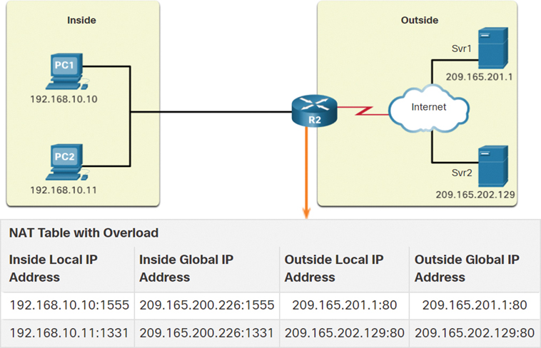
Figure 6-7 PAT Scenario
As R2 processes each packet, it uses a port number (such as 1331 and 1555 in this example) to identify the device from which the packet originated. The source address (SA) is the inside local address with the TCP/UDP assigned port number added. The destination address (DA) is the outside global address with the service port number added. In this example, the service port is 80, which is HTTP.
For the source address, R2 translates the inside local address to an inside global address with the port number added. The destination address is not changed but is now referred to as the outside global IPv4 address. When the web server replies, the path is reversed.
Next Available Port (6.2.4)
In the previous example, the client port numbers, 1331 and 1555, did not change at the NAT-enabled router. This is not a very likely scenario because there is a good chance that these port numbers may have already been attached to other active sessions.
PAT attempts to preserve the original source port. However, if the original source port is already used, PAT assigns the first available port number starting from the beginning of the appropriate port group 0 through 511, 512 through 1023, or 1024 through 65,535. When there are no more ports available and there is more than one external address in the address pool, PAT moves to the next address to try to allocate the original source port. This process continues until there are no more available ports or external IPv4 addresses.
In Figure 6-8, PAT has assigned the next available port (1445) to the second host address.

Figure 6-8 Source Port Reassignment
In the figure, the hosts have chosen the same port number, 1444. This is acceptable for the inside address because the hosts have unique private IPv4 addresses. However, at the NAT router, the port numbers must be changed; otherwise, packets from two different hosts would exit R2 with the same source address. This example assumes that the first 420 ports in the range 1024–65,535 are already in use, so the next available port number, 1445, is used.
When packets are returned from outside the network, if the source port number was previously modified by the NAT-enabled router, the destination port number is now changed back to the original port number by the NAT-enabled router.
NAT and PAT Comparison (6.2.5)
Table 6-2 provides a summary of the differences between NAT and PAT.
Table 6-2 NAT and PAT
NAT |
PAT |
One-to-one mapping between inside local and inside global addresses. |
One inside global address can be mapped to many inside local addresses. |
Uses only IPv4 addresses in the translation process. |
Uses IPv4 addresses and TCP or UDP source port numbers in the translation process. |
A unique inside global address is required for each inside host accessing the outside network. |
A single unique inside global address can be shared by many inside hosts accessing the outside network. |
NAT
Table 6-3 shows a simple example of a NAT table. In this example, four hosts on the internal network are communicating to the outside network. The left column lists the addresses in the global address pool that NAT uses to translate the inside local address of each host. Note the one-to-one relationship of inside global addresses to inside local addresses for each of the four hosts accessing the outside network. With NAT, an inside global address is needed for each host that needs to connect to the outside network.
Note
NAT forwards the incoming return packets to the original inside host by referring to the table and translating the inside global address back to the corresponding inside local address of the host.
Table 6-3 NAT Table
Inside Global Address |
Inside Local Address |
209.165.200.226 |
192.168.10.10 |
209.165.200.227 |
192.168.10.11 |
209.165.200.228 |
192.168.10.12 |
209.165.200.229 |
192.168.10.13 |
PAT
Whereas NAT only modifies the IPv4 addresses, PAT modifies both the IPv4 address and the port number. With PAT, there is generally only one or very few publicly exposed IPv4 addresses. The NAT table in Table 6-4 shows one inside global address being used to translate the inside local addresses of the four inside hosts. PAT uses the Layer 4 port number to track the conversations of the four hosts.
Table 6-4 NAT Table with PAT
Inside Global Address |
Inside Local Address |
209.165.200.226:2031 |
192.168.10.10:2031 |
209.165.200.226:1506 |
192.168.10.11:1506 |
209.165.200.226:1131 |
192.168.10.12:1131 |
209.165.200.226:1718 |
192.168.10.13:1718 |
Packets Without a Layer 4 Segment (6.2.6)
What about IPv4 packets carrying data other than a TCP or UDP segment? These packets do not contain a Layer 4 port number. PAT translates most common protocols carried by IPv4 that do not use TCP or UDP as transport layer protocols. The most common of these is ICMPv4. Each of these types of protocols is handled differently by PAT. For example, ICMPv4 query messages, echo requests, and echo replies include a Query ID field. ICMPv4 uses the Query ID field to identify an echo request with its corresponding echo reply. The Query ID field is incremented with each echo request sent. PAT uses the Query ID field instead of a Layer 4 port number.
Note
Other ICMPv4 messages do not use the Query ID field. These messages and other protocols that do not use TCP or UDP port numbers vary and are beyond the scope of this chapter.
Packet Tracer—Investigate NAT Operations (6.2.7)

You know that as a frame travels across a network, the MAC addresses change. But IPv4 addresses can also change when a packet is forwarded by a device configured with NAT. In this activity, you will see what happens to IPv4 addresses during the NAT process.
In this Packet Tracer activity, you will
Investigate NAT operation across the intranet
Investigate NAT operation across the internet
Conduct further investigations
NAT Advantages and Disadvantages (6.3)
NAT solves the problem of not having enough IPv4 addresses, but it can also create other problems. This section addresses the advantages and disadvantage of NAT.
Advantages of NAT (6.3.1)
NAT provides many benefits, including the following:
NAT conserves the legally registered addressing scheme by allowing the privatization of intranets. NAT conserves addresses through application port-level multiplexing. With NAT overload (PAT), internal hosts can share a single public IPv4 address for all external communications. In this type of configuration, very few external addresses are required to support many internal hosts.
NAT increases the flexibility of connections to the public network. Multiple pools, backup pools, and load-balancing pools can be implemented to ensure reliable public network connections.
NAT provides consistency for internal network addressing schemes. On a network not using private IPv4 addresses and NAT, changing the public IPv4 address scheme requires the readdressing of all hosts on the existing network. The costs of readdressing hosts can be significant. NAT allows the existing private IPv4 address scheme to remain while allowing for easy change to a new public addressing scheme. This means an organization could change ISPs and not need to change any of its inside clients.
Using RFC 1918 IPv4 addresses, NAT hides the IPv4 addresses of users and other devices. Some people consider this a security feature; however, most experts agree that NAT does not provide security. A stateful firewall provides security on the edge of the network.
Disadvantages of NAT (6.3.2)
NAT does have drawbacks. The fact that hosts on the internet appear to communicate directly with the NAT-enabled device, rather than with the actual host inside the private network, creates a number of issues.
One disadvantage of using NAT is related to network performance, particularly for real-time protocols such as VoIP. NAT increases forwarding delays because the translation of each IPv4 address within the packet headers takes time. The first packet is always process switched, going through the slower path. The router must look at every packet to decide whether it needs translation. The router must alter the IPv4 header, and it may also alter the TCP or UDP header. The IPv4 header checksum, along with the TCP or UDP checksum, must be recalculated each time a translation is made. Remaining packets go through the fast-switched path if a cache entry exists; otherwise, they too are delayed.
The forwarding delays caused by the NAT process become more of an issue as the pools of public IPv4 addresses for ISPs become depleted. Many ISPs are having to assign customers private IPv4 addresses instead of public IPv4 addresses. Such a customer's router translates a packet from its private IPv4 address to the private IPv4 address of the ISP. Before forwarding the packet to another provider, the ISP performs NAT again, translating a private IPv4 address to one of its limited number of public IPv4 addresses. This process of two layers of NAT translation is known as carrier-grade NAT (CGN).
Another disadvantage of using NAT is that end-to-end addressing is lost. This is known as the end-to-end principle. Many internet protocols and applications depend on end-to-end addressing from the source to the destination. Some applications do not work with NAT. For example, some security applications, such as digital signatures, fail because the source IPv4 address changes before reaching the destination. Applications that use physical addresses instead of a qualified domain name do not reach destinations that are translated across the NAT router. Sometimes this problem can be avoided by implementing static NAT mappings.
Another disadvantage of using NAT is that end-to-end IPv4 traceability is also lost. It becomes much more difficult to trace packets that undergo numerous packet address changes over multiple NAT hops, making troubleshooting challenging.
Using NAT also complicates the use of tunneling protocols, such as IPsec, because NAT modifies values in the headers, causing integrity checks to fail.
Services that require the initiation of TCP connections from the outside network, or stateless protocols, such as those using UDP, can be disrupted. Unless a NAT router has been configured to support such protocols, incoming packets cannot reach their destination. Some protocols can accommodate one instance of NAT between participating hosts (passive mode FTP, for example) but fail when both systems are separated from the internet by NAT.
Check Your Understanding—NAT Advantages and Disadvantages (6.3.3)
Refer to the online course to complete this activity.
Static NAT (6.4)
In this section, you will learn how to configure and verify static NAT. It includes a Packet Tracer activity to test your skills and knowledge. Static NAT is a one-to-one mapping between an inside address and an outside address. Static NAT allows external devices to initiate connections to internal devices using statically assigned public addresses. For instance, an internal web server may be mapped to a specific inside global address so that it is accessible from outside networks.
Static NAT Scenario (6.4.1)
Figure 6-9 shows an inside network containing a web server with a private IPv4 address. Router R2 is configured with static NAT to allow devices on the outside network (internet) to access the web server. The client on the outside network accesses the web server using a public IPv4 address. Static NAT translates the public IPv4 address to the private IPv4 address.

Figure 6-9 Static NAT Topology
Configure Static NAT (6.4.2)
There are two basic steps when configuring static NAT translations:
Step 1. The first task is to create a mapping between the inside local address and the inside global addresses. In Example 6-1, the 192.168.10.254 inside local address and the 209.165.201.5 inside global address in Figure 6-9 are configured as a static NAT translation.
Example 6-1 Static NAT Configuration
R2(config)# ip nat inside source static 192.168.10.254 209.165.201.5
R2(config)#
Step 2. After the mapping is configured, the interfaces participating in the translation are configured as inside or outside relative to NAT. In Example 6-2, the R2 Serial 0/1/0 interface is an inside interface, and Serial 0/1/1 is an outside interface.
Example 6-2 Configuring Inside and Outside NAT Interfaces
R2(config)# interface serial 0/1/0
R2(config-if)# ip address 192.168.1.2 255.255.255.252
R2(config-if)# ip nat inside
R2(config-if)# exit
R2(config)# interface serial 0/1/1
R2(config-if)# ip address 209.165.200.1 255.255.255.252
R2(config-if)# ip nat outside
R2(config-if)#
With this configuration in place, packets arriving on the inside interface of R2 (Serial 0/1/0) from the configured inside local IPv4 address (192.168.10.254) are translated and then forwarded toward the outside network. Packets arriving on the outside interface of R2 (Serial 0/1/1) that are addressed to the configured inside global IPv4 address (209.165.201.5) are translated to the inside local address (192.168.10.254) and then forwarded to the inside network.
Analyze Static NAT (6.4.3)
Using the previous configuration, Figure 6-10 illustrates the static NAT translation process between the client and the web server. Usually static translations are used when clients on the outside network (internet) need to reach servers on the inside (internal) network. The following steps are illustrated in Figure 6-10:

Figure 6-10 Static NAT Process
Step 1. The client wants to open a connection to the web server. The client sends a packet to the web server using the public IPv4 destination address 209.165.201.5. This is the inside global address of the web server.
Step 2. The first packet that R2 receives from the client on its NAT outside interface causes R2 to check its NAT table. The destination IPv4 address 209.165.201.5 is located in the NAT table and is translated to 192.168.10.254.
Step 3. R2 replaces the inside global address 209.165.201.5 with the inside local address 192.168.10.254. R2 then forwards the packet toward the web server.
Step 4. The web server receives the packet and responds to the client using the inside local address 192.168.10.254 as the source address of the response packet.
Step 5. a. R2 receives the packet from the web server on its NAT inside interface with the source address of the inside local address of the web server, 192.168.10.254.
b. R2 checks the NAT table for a translation for the inside local address. The address is found in the NAT table. R2 translates the source address 192.168.10.254 to the inside global address 209.165.201.5 and forwards the packet toward the client.
Step 6. (Not shown) The client receives the packet and continues the conversation. The NAT router performs steps 2 to 5b for each packet.
Verify Static NAT (6.4.4)
To verify NAT operation, issue the show ip nat translations command, as shown in Example 6-3. This command shows active NAT translations. Because the example is a static NAT configuration, the translation is always present in the NAT table, regardless of any active communications.
Example 6-3 Static NAT Translations: Always in the NAT Table
R2# show ip nat translations
Pro  Inside global       Inside local       Outside local     Outside global
---  209.165.201.5       192.168.10.254     ---               ---
Total number of translations: 1
R2#
If the command is issued during an active session, the output also indicates the address of the outside device, as shown in Example 6-4.
Example 6-4 Static NAT Translation During an Active Session
R2# show ip nat translations
Pro  Inside global       Inside local        Outside local         Outside global
tcp  209.165.201.5       192.168.10.254      209.165.200.254       209.165.200.254
---  209.165.201.5       192.168.10.254        ---                   ---
Total number of translations: 2
R2#
Another useful command is show ip nat statistics, which displays information about the total number of active translations, the NAT configuration parameters, the number of addresses in the pool, and the number of addresses that have been allocated, as shown in Example 6-5.
To verify that NAT translation is working, it is best to clear statistics from any past translations by using the clear ip nat statistics command before testing.
Example 6-5 NAT Statistics Before an Active Session Is Established
R2# show ip nat statistics
Total active translations: 1 (1 static, 0 dynamic; 0 extended)
Outside interfaces:
  Serial0/1/1
Inside interfaces:
  Serial0/1/0
Hits: 0  Misses: 0
(output omitted)
R2#
After the client establishes a session with the web server, the show ip nat statistics command displays an increase to 4 hits on the inside (Serial0/1/0) interface, as shown in Example 6-6. This verifies that the static NAT translation is taking place on R2.
Example 6-6 NAT Statistics After an Active Session Is Established
R2# show ip nat statistics
Total active translations: 1 (1 static, 0 dynamic; 0 extended)
Outside interfaces:
  Serial0/1/1
Inside interfaces:
  Serial0/1/0
Hits: 4  Misses: 1
(output omitted)
R2#
Packet Tracer—Configure Static NAT (6.4.5)
In IPv4 configured networks, clients and servers use private addressing. Before packets with private addressing can cross the internet, they need to be translated to public addressing. A server that is accessed from outside the organization is usually assigned both a public IPv4 address and a private static IPv4 address. In this activity, you will configure static NAT so that outside devices can access an inside server at its public address.
In this Packet Tracer activity, you will
Test access without NAT
Configure static NAT
Dynamic NAT (6.5)
In this section, you will learn how to configure and verify dynamic NAT. It includes a Packet Tracer activity to test your skills and knowledge. Whereas static NAT provides a permanent mapping between an inside local address and an inside global address, dynamic NAT automatically maps inside local addresses to inside global addresses. These inside global addresses are typically public IPv4 addresses. Dynamic NAT, like static NAT, requires the configuration of the inside and outside interfaces participating in NAT with the ip nat inside and ip nat outside interface configuration commands. However, whereas static NAT creates a permanent mapping to a single address, dynamic NAT uses a pool of addresses.
Dynamic NAT Scenario (6.5.1)
The sample topology shown in Figure 6-11 has an inside network using addresses from the RFC 1918 private address space. Attached to router R1 are two LANs, 192.168.10.0/24 and 192.168.11.0/24. Router R2, the border router, is configured for dynamic NAT, using the pool of public IPv4 addresses 209.165.200.226 through 209.165.200.240.
The pool of public IPv4 addresses (that is, the inside global address pool) is available to any device on the inside network on a first-come, first-served basis. With dynamic NAT, a single inside address is translated to a single outside address. With this type of translation, there must be enough addresses in the pool to accommodate all the inside devices needing concurrent access to the outside network. If all addresses in the pool are in use, a device must wait for an available address before it can access the outside network.

Figure 6-11 Dynamic NAT Topology
Note
Translating between public and private IPv4 addresses is by far the most common use of NAT. However, NAT translations can occur between pairs of IPv4 addresses.
Configure Dynamic NAT (6.5.2)
Figure 6-11 shows a sample topology where the NAT configuration allows translation for all hosts on the 192.168.0.0/16 network. This includes the 192.168.10.0 and 192.168.11.0 LANs when the hosts generate traffic that enters interface S0/1/0 and exits S0/1/1. The host inside local addresses are translated to an available pool address in the range 209.165.200.226 to 209.165.200.240.
Step 1. Define the pool of addresses that will be used for translation using the ip nat pool global configuration command. This pool of addresses is typically a group of public addresses. The addresses are defined by indicating the starting IPv4 address and the ending IPv4 address of the pool. The netmask or prefix-length keyword indicates which address bits belong to the network and which bits belong to the host for that range of addresses.
In this scenario, define a pool of public IPv4 addresses under the pool name NAT-POOL1, as shown in Example 6-7.
Example 6-7 Configuring a NAT Pool
R2(config)# ip nat pool NAT-POOL1 209.165.200.226 209.165.200.240 netmask
  255.255.255.224
R2(config)#
Step 2. Configure a standard ACL to identify (permit) only those addresses that are to be translated. An ACL that is too permissive can lead to unpredictable results. Remember that there is an implicit deny all statement at the end of each ACL.
In this scenario, define which addresses are eligible to be translated, as shown in Example 6-8.
Example 6-8 Defining the Traffic That Will Be Translated
R2(config)# access-list 1 permit 192.168.0.0 0.0.255.255
R2(config)#
Step 3. Bind the ACL to the pool, using the following command syntax:
Router(config)# ip nat inside source list {access-list-number |
   access-list-name} pool pool-name
The router uses this configuration to identify which devices (list) receive which addresses (pool). In the scenario, bind NAT-POOL1 with ACL 1, as shown in Example 6-9.
Example 6-9 Binding an ACL to a Pool
R2(config)# ip nat inside source list 1 pool NAT-POOL 1
Step 4. Identify which interfaces are inside, in relation to NAT; these will be any interfaces that connect to the inside network.
In this scenario, identify interface serial 0/1/0 as an inside NAT interface, as shown in Example 6-10.
Example 6-10 Configuring the Inside NAT Interface
R2(config)# interface serial 0/1/0
R2(config-if)# ip nat inside
Step 5. Identify which interfaces are outside, in relation to NAT; these will be any interfaces that connect to the outside network.
In this scenario, identify interface serial 0/1/1 as the outside NAT interface, as shown in Example 6-11.
Example 6-11 Configuring the Outside NAT Interface
R2(config)# interface serial 0/1/1
R2(config-if)# ip nat outside
Analyze Dynamic NAT—Inside to Outside (6.5.3)
Using the previous configuration, Figures 6-12 and 6-13 illustrate the dynamic NAT translation process between two clients and the web server.
Figure 6-12 illustrates the traffic flow from the inside network to the outside network:

Figure 6-12 Dynamic NAT Process: Inside to Outside
Step 1. The hosts with the source IPv4 addresses 192.168.10.10 (PC1) and 192.168.11.10 (PC2) send packets requesting a connection to the server at the public IPv4 address 209.165.200.254.
Step 2. R2 receives the first packet from host 192.168.10.10. Because this packet was received on an interface configured as an inside NAT interface, R2 checks the NAT configuration to determine if this packet should be translated. The ACL permits this packet, so R2 translates the packet. R2 checks its NAT table. Because there is no current translation entry for this IPv4 address, R2 determines that the source address 192.168.10.10 must be translated. R2 selects an available global address from the dynamic address pool and creates a translation entry, 209.165.200.226. The original source IPv4 address 192.168.10.10 is the inside local address, and the translated address is the inside global address 209.165.200.226 in the NAT table. For the second host, 192.168.11.10, R2 repeats the procedure, selects the next available global address from the dynamic address pool, and creates a second translation entry, 209.165.200.227.
Step 3. R2 replaces the inside local source address of PC1, 192.168.10.10, with the translated inside global address of 209.165.200.226 and forwards the packet. The same process occurs for the packet from PC2, using the translated address 209.165.200.227.
Analyze Dynamic NAT—Outside to Inside (6.5.4)
Figure 6-13 illustrates the remainder of the traffic flow between the clients and the server in the outside-to-inside direction:

Figure 6-13 Dynamic NAT Process: Outside to Inside
Step 4. The server receives the packet from PC1 and responds using the IPv4 destination address 209.165.200.226. When the server receives the second packet, it responds to PC2 using the IPv4 destination address 209.165.200.227.
Step 5. a. When R2 receives the packet with the destination IPv4 address 209.165.200.226, it performs a NAT table lookup. Using the mapping from the table, R2 translates the address back to the inside local address 192.168.10.10 and forwards the packet toward PC1.
b. When R2 receives the packet with the destination IPv4 address 209.165.200.227, it performs a NAT table lookup. Using the mapping from the table, R2 translates the address back to the inside local address 192.168.11.10 and forwards the packet toward PC2.
Step 6. PC1 at 192.168.10.10 and PC2 at 192.168.11.10 receive the packets and continue the conversation. The router performs steps 2 to 5 for each packet. (Step 6 is not shown in the figures.)
Verify Dynamic NAT (6.5.5)
The output of the show ip nat translations command in Example 6-12 displays all static translations that have been configured and any dynamic translations that have been created by traffic.
Example 6-12 Verifying NAT Translations
R2# show ip nat translations
Pro Inside global      Inside local       Outside local      Outside global
--- 209.165.200.228    192.168.10.10      ---                ---
--- 209.165.200.229    192.168.11.10      ---                ---
R2#
Adding the verbose keyword displays additional information about each translation, including how long ago the entry was created and used, as shown in Example 6-13.
Example 6-13 Verifying Verbose NAT Translations
R2# show ip nat translation verbose
Pro Inside global      Inside local       Outside local      Outside global
tcp 209.165.200.228    192.168.10.10      ---                ---
    create 00:02:11, use 00:02:11 timeout:86400000, left 23:57:48, Map-Id(In): 1,
    flags:
none, use_count: 0, entry-id: 10, lc_entries: 0
tcp 209.165.200.229    192.168.11.10      ---                ---
    create 00:02:10, use 00:02:10 timeout:86400000, left 23:57:49, Map-Id(In): 1,
    flags:
none, use_count: 0, entry-id: 12, lc_entries: 0
R2#
By default, translation entries time out after 24 hours unless the timers have been reconfigured with the ip nat translation timeout timeout-seconds global configuration mode command.
To clear dynamic entries before the timeout has expired, use the clear ip nat translation privileged EXEC mode command, as shown in Example 6-14.
Example 6-14 Clearing NAT Translations
R2# clear ip nat translation *
R2# show ip nat translation
R2#
It is useful to clear the dynamic entries when testing NAT configuration. The clear ip nat translation command can be used with keywords and variables to control which entries are cleared, as shown in Table 6-5. Specific entries can be cleared to avoid disrupting active sessions. Use the clear ip nat translation * privileged EXEC command to clear all translations from the table.
Table 6-5 The clear ip nat translation Command
Command |
Description |
clear ip nat translation * |
Clears all dynamic address translation entries from the NAT translation table. |
clear ip nat translation inside global-ip local-ip [outside local-ip global-ip] |
Clears a simple dynamic translation entry containing an inside translation or both inside and outside translation. |
clear ip nat translation protocol inside global-ip global-port local-ip local-port [outside local-ip local-port global-ip global-port] |
Clears an extended dynamic translation entry. |
Note
Only the dynamic translations are cleared from the table. Static translations cannot be cleared from the translation table.
Another useful command, show ip nat statistics, displays information about the total number of active translations, the NAT configuration parameters, the number of addresses in the pool, and how many of the addresses have been allocated, as shown in Example 6-15.
Example 6-15 Verifying NAT Statistics
R2# show ip nat statistics
Total active translations: 4 (0 static, 4 dynamic; 0 extended)
Peak translations: 4, occurred 00:31:43 ago
Outside interfaces:
  Serial0/1/1
Inside interfaces:
  Serial0/1/0
Hits: 47  Misses: 0
CEF Translated packets: 47, CEF Punted packets: 0
Expired translations: 5
Dynamic mappings:
-- Inside Source
[Id: 1] access-list 1 pool NAT-POOL1 refcount 4
 pool NAT-POOL1: netmask 255.255.255.224
       start 209.165.200.226 end 209.165.200.240
       type generic, total addresses 15, allocated 2 (13%), misses 0
(output omitted)
R2#
Alternatively, you can use the show running-config command and look for NAT, ACL, interface, or pool commands with the required values. Examine these carefully and correct any errors discovered. Example 6-16 shows the NAT pool configuration.
Example 6-16 Verifying the NAT Configuration
R2# show running-config | include NAT
ip nat pool NAT-POOL1 209.165.200.226 209.165.200.240 netmask 255.255.255.224
ip nat inside source list 1 pool NAT-POOL1
R2#
Packet Tracer—Configure Dynamic NAT (6.5.6)
In this Packet Tracer, you will complete the following objectives:
Configure dynamic NAT
Verify NAT implementation
PAT (6.6)
In this section, you will learn how to configure and verify PAT. It includes a Packet Tracer activity to test your skills and knowledge.
PAT Scenario (6.6.1)
There are two ways to configure PAT, depending on how the ISP allocates public IPv4 addresses. First, the ISP can allocate a single public IPv4 address that is required for the organization to connect to the ISP; alternatively, the ISP can allocate more than one public IPv4 address to the organization. Both methods are demonstrated using the scenario shown in Figure 6-14.

Figure 6-14 PAT Topology
Configure PAT to Use a Single IPv4 Address (6.6.2)
To configure PAT to use a single IPv4 address, simply add the keyword overload to the ip nat inside source global configuration command. The rest of the configuration is similar to the configuration for static and dynamic NAT except that with PAT, multiple hosts can use the same public IPv4 address to access the internet.
In Example 6-17, all hosts from network 192.168.0.0/16 (matching ACL 1) that send traffic through router R2 to the internet are translated to IPv4 address 209.165.200.225 (which is the IPv4 address of interface S0/1/1). The traffic flows are identified by port numbers in the NAT table because the overload keyword is configured.
Example 6-17 PAT Configuration to Overload an Interface
R2(config)# ip nat inside source list 1 interface serial 0/1/0 overload
R2(config)# access-list 1 permit 192.168.0.0 0.0.255.255
R2(config)#
R2(config)# interface serial0/1/0
R2(config-if)# ip nat inside
R2(config-if)# exit
R2(config)#
R2(config)# interface Serial0/1/1
R2(config-if)# ip nat outside
R2(config-if)# exit
R2(config)#
Configure PAT to Use an Address Pool (6.6.3)
An ISP may allocate more than one public IPv4 address to an organization. In such a case, the organization can configure PAT to use a pool of IPv4 public addresses for translation.
If a site has been issued more than one public IPv4 address, these addresses can be part of a pool that is used by PAT. The small pool of addresses is shared among a larger number of devices, with multiple hosts using the same public IPv4 address to access the internet. To configure PAT for a dynamic NAT address pool, simply add the keyword overload to the ip nat inside source global configuration command.
The same topology from the preceding example is used for this scenario and repeated in Figure 6-15 for your convenience.

Figure 6-15 PAT with a Single Address Topology
In Example 6-18, NAT-POOL2 is bound to an ACL to permit 192.168.0.0/16 to be translated. These hosts can share an IPv4 address from the pool because PAT is enabled with the keyword overload.
Example 6-18 PAT Configuration to Overload a NAT Pool
R2(config)# ip nat pool NAT-POOL2 209.165.200.226 209.165.200.240 netmask 255.255.255.224
R2(config)# access-list 1 permit 192.168.0.0 0.0.255.255
R2(config)# ip nat inside source list 1 pool NAT-POOL2 overload
R2(config)#
R2(config)# interface serial0/1/0
R2(config-if)# ip nat inside
R2(config-if)# exit
R2(config)#
R2(config)# interface serial0/1/0
R2(config-if)# ip nat outside
R2(config-if)# end
R2#
Analyze PAT—PC to Server (6.6.4)
The process of NAT overload is the same whether a single address or a pool of addresses is used. In Figure 6-16, PAT is configured to use a single public IPv4 address instead of a pool of addresses. PC1 wants to communicate with the web server Svr1. At the same time, another client, PC2, wants to establish a similar session with the web server Svr2. Both PC1 and PC2 are configured with private IPv4 addresses and with R2 enabled for PAT.

Figure 6-16 PAT Process: PCs to Servers
The following steps are illustrated in Figure 6-16:
Step 1. PC1 is sending packets to Svr1, and PC2 is sending packets to Svr2. PC1 has the source IPv4 address 192.168.10.10 and is using TCP source port 1444. PC2 has the source IPv4 address 192.168.10.11 and coincidentally uses the same TCP source port, 1444.
Step 2. The packet from PC1 reaches R2 first. Using PAT, R2 modifies the source IPv4 address to 209.165.200.225 (inside global address). There are no other devices in the NAT table using port 1444, so PAT maintains the same port number. The packet is then forwarded toward Svr1 at 209.165.201.1.
Step 3. The packet from PC2 arrives at R2. PAT is configured to use a single inside global IPv4 address, 209.165.200.225, for all translations. Much as in the translation process for PC1, PAT changes the source IPv4 address of PC2 to the inside global address 209.165.200.225. However, PC2 has the same source port number as a current PAT entry, the translation for PC1. PAT increments the source port number until it is a unique value in its table. In this instance, the source port entry in the NAT table and the packet for PC2 receives 1445.
Analyze PAT—Server to PC (6.6.5)
Although PC1 and PC2 are using the same translated address, the inside global address 209.165.200.225, and the same source port number 1444, the modified port number for PC2 (1445) makes each entry in the NAT table unique. This becomes evident with the packets sent from the servers back to the clients, as shown in Figure 6-17.
The following steps from the servers to the PCs are illustrated in Figure 6-17:
Step 4. The servers use the source port from the received packet as the destination port and the source address as the destination address for the return traffic. The servers seem as if they are communicating with the same host at 209.165.200.225; however, this is not the case.
Step 5. As the packets arrive, R2 locates the unique entry in its NAT table, using the destination address and the destination port of each packet. In the case of the packet from Svr1, the destination IPv4 address 209.165.200.225 has multiple entries but only one with the destination port 1444. Using the entry in its table, R2 changes the destination IPv4 address of the packet to 192.168.10.10, with no change required for the destination port. The packet is then forwarded toward PC1.
Step 6. When the packet from Svr2 arrives, R2 performs a similar translation. The destination IPv4 address 209.165.200.225 is located, again with multiple entries. However, using the destination port 1445, R2 is able to uniquely identify the translation entry. The destination IPv4 address is changed to 192.168.10.11. In this case, the destination port must also be modified back to its original value of 1444, which is stored in the NAT table. The packet is then forwarded toward PC2.

Figure 6-17 PAT Process: Servers to PCs
Verify PAT (6.6.6)
Router R2 has been configured to provide PAT to the 192.168.0.0/16 clients. When an internal host sends communication through router R2 to the internet, its address is translated to an IPv4 address from the PAT pool with a unique source port number.
The same commands used to verify static and dynamic NAT are used to verify PAT, as shown in Example 6-19. The show ip nat translations command displays the translations from two different hosts to different web servers. Notice that two different inside hosts are allocated the same IPv4 address, 209.165.200.226 (inside global address). The source port numbers in the NAT table differentiate the two transactions.
Example 6-19 Verifying NAT Translations
R2# show ip nat translations
Pro Inside global        Inside local       Outside local      Outside global
tcp 209.165.200.225:1444 192.168.10.10:1444 209.165.201.1:80   209.165.201.1:80
tcp 209.165.200.225:1445 192.168.11.10:1444 209.165.202.129:80 209.165.202.129:80
R2#
In Example 6-20, the show ip nat statistics command verifies that NAT-POOL2 has allocated a single address for both translations. The output includes information about the number and type of active translations, the NAT configuration parameters, the number of addresses in the pool, and how many have been allocated.
Example 6-20 Verifying NAT Statistics
R2# show ip nat statistics
Total active translations: 4 (0 static, 2 dynamic; 2 extended)
Peak translations: 2, occurred 00:31:43 ago
Outside interfaces:
  Serial0/1/1
Inside interfaces:
  Serial0/1/0
Hits: 4  Misses: 0
CEF Translated packets: 47, CEF Punted packets: 0
Expired translations: 0
Dynamic mappings:
-- Inside Source
[Id: 3] access-list 1 pool NAT-POOL2 refcount 2
 pool NAT-POOL2: netmask 255.255.255.224
       start 209.165.200.225 end 209.165.200.240
       type generic, total addresses 15, allocated 1 (6%), misses 0
(output omitted)
R2#
Packet Tracer—Configure PAT (6.6.7)
In this Packet Tracer activity, you will complete the following objectives:
Part 1: Configure dynamic NAT with overload
Part 2: Verify dynamic NAT with overload implementation
Part 3: Configure PAT using an interface
Part 4: Verify PAT interface implementation
NAT64 (6.7)
In this section, you will learn how NAT is used with IPv6 networks.
NAT for IPv6? (6.7.1)
Because many networks use both IPv4 and IPv6, administrators need to have a way to use IPv6 with NAT. This section discusses how IPv6 can be integrated with NAT.
IPv6, with a 128-bit address, provides 340 undecillion addresses. Therefore, address space is not an issue with IPv6 as it is with IPv4. IPv6 was developed with the intention of making NAT for IPv4—with translation between public and private IPv4 addresses—unnecessary. However, IPv6 does include its own IPv6 private address space, referred to as unique local addresses (ULAs).
IPv6 ULAs are similar to RFC 1918 private addresses in IPv4 but have a different purpose. ULAs are meant for only local communications within a site; they are not meant to provide additional IPv6 address space or to provide security.
IPv6 provides for protocol translation between IPv4 and IPv6 through NAT64.
NAT64 (6.7.2)
NAT for IPv6 is used in a much different context than NAT for IPv4. NAT64 is used to transparently provide access between IPv6-only and IPv4-only networks, as shown in Figure 6-18. It is not used as a form of private IPv6-to-global IPv6 translation.

Figure 6-18 IPv6 and IPv4 Networks Translated by a NAT64 Router
Ideally, IPv6 should be run natively wherever possible; that is, IPv6 devices should communicate with each other over IPv6 networks. However, to aid in the move from IPv4 to IPv6, the IETF has developed several transition techniques to accommodate a variety of IPv4-to-IPv6 scenarios, including dual stack, tunneling, and translation.
With dual stack, devices run protocols associated with both IPv4 and IPv6. Tunneling for IPv6 is the process of encapsulating an IPv6 packet inside an IPv4 packet. This allows the IPv6 packet to be transmitted over an IPv4-only network.
NAT for IPv6 should not be used as a long-term strategy but as a temporary mechanism to assist in the migration from IPv4 to IPv6. Over the years, there have been several types of NAT for IPv6, including Network Address Translation–Protocol Translation (NAT-PT). However, the IETF has deprecated NAT-PT and favors its replacement, NAT64. NAT64 is beyond the scope of this chapter.
Summary (6.8)
The following is a summary of the sections in this chapter.
NAT Characteristics
The limited number of public IPv4 addresses means there are not enough to assign a unique address to each device connected to the internet. Private IPv4 addresses cannot be routed over the internet. To allow a device with a private IPv4 address to access devices and resources outside the local network, the private address must be translated to a public address. NAT translates between private addresses and public addresses. The primary goal with NAT is to conserve public IPv4 addresses. It allows networks to use private IPv4 addresses internally and provides translation to a public address only when needed. When an internal device sends traffic out the network, the NAT-enabled router translates the internal IPv4 address of the device to a public address from the NAT pool. In NAT terminology, the inside network is the set of networks that is subject to translation, and the outside network is all other networks. When determining which type of address is used, it is important to remember that NAT terminology is always applied from the perspective of the device with the translated address:
Inside address: The address of the device that is being translated by NAT
Outside address: The address of the destination device
NAT also uses the concept of local or global with respect to addresses:
Local address: Any address that appears on the inside portion of the network
Global address: Any address that appears on the outside portion of the network
Types of NAT
Static NAT uses a one-to-one mapping of local and global addresses. These mappings are configured by the network administrator and remain constant. Static NAT is particularly useful for a web server or any other device that must have a consistent address that is accessible from the internet, such as a company web server. Static NAT requires that enough public addresses be available to satisfy the total number of simultaneous user sessions. Dynamic NAT uses a pool of public addresses and assigns them on a first-come, first-served basis. When an inside device requests access to an outside network, dynamic NAT assigns an available public IPv4 address from the pool. Like static NAT, dynamic NAT requires that enough public addresses be available to satisfy the total number of simultaneous user sessions. Port Address Translation (PAT), also known as NAT overload, maps multiple private IPv4 addresses to a single public IPv4 address or a few addresses. This is the most common form of NAT for both homes and enterprises. PAT ensures that devices use a different TCP port number for each session with a server on the internet. PAT attempts to preserve the original source port. However, if the original source port is already used, PAT assigns the first available port number, starting from the beginning of the appropriate port group. PAT translates most common protocols carried by IPv4 that do not use TCP or UDP as a transport layer protocol. The most common of these is ICMPv4.
Table 6-6 provides a summary of the differences between NAT and PAT.
Table 6-6 NAT and PAT
NAT |
PAT |
One-to-one mapping between inside local and inside global addresses. |
One inside global address can be mapped to many inside local addresses. |
Uses only IPv4 addresses in the translation process. |
Uses IPv4 addresses and TCP or UDP source port numbers in the translation process. |
A unique inside global address is required for each inside host accessing the outside network. |
A single unique inside global address can be shared by many inside hosts accessing the outside network. |
NAT Advantages and Disadvantages
NAT has a number of advantages: NAT conserves the legally registered addressing scheme by allowing the privatization of intranets. NAT increases the flexibility of connections to the public network. NAT provides consistency for internal network addressing schemes. NAT hides user IPv4 addresses.
NAT has a number of disadvantages: NAT increases forwarding delays because the translation of each IPv4 address within the packet headers takes time. The process of using two layers of NAT translation is known as carrier-grade NAT (CGN). End-to-end addressing is lost, but many internet protocols and applications depend on end-to-end addressing from the source to the destination. End-to-end IPv4 traceability is also lost. Using NAT also complicates the use of tunneling protocols, such as IPsec, because NAT modifies values in the headers, causing integrity checks to fail.
Static NAT
Static NAT is a one-to-one mapping between an inside address and an outside address. Static NAT allows external devices to initiate connections to internal devices using the statically assigned public address. The first task is to create a mapping between the inside local address and the inside global address, using the ip nat inside source static global configuration command. After the mapping is configured, the interfaces participating in the translation are configured as inside or outside relative to NAT using the ip nat inside and ip nat outside interface configuration commands. To verify NAT operations, use the show ip nat translations command. To verify that NAT translation is working, it is best to clear statistics from any past translations by using the clear ip nat statistics privileged EXEC command before testing.
Dynamic NAT
Dynamic NAT automatically maps inside local addresses to inside global addresses. Dynamic NAT, like static NAT, requires the configuration of the inside and outside interfaces participating in NAT. Dynamic NAT uses a pool of addresses translating a single inside address to a single outside address. The pool of public IPv4 addresses (that is, the inside global address pool) is available to any devices on the inside network on a first-come, first-served basis. With this type of translation, there must be enough addresses in the pool to accommodate all the inside devices needing concurrent access to the outside network. If all addresses in the pool are in use, a device must wait for an available address before it can access the outside network.
To configure dynamic NAT, first define the pool of addresses that will be used for translation by using the ip nat pool global configuration command. The addresses are defined by indicating the starting IPv4 address and the ending IPv4 address of the pool. The netmask or prefix-length keyword indicates which address bits belong to the network and which bits belong to the host for the range of addresses. Configure a standard ACL to identify (permit) only those addresses that are to be translated. Bind the ACL to the pool, using the following command syntax: Router(config)# ip nat inside source list {access-list-number | access-list-name} pool pool-name. Identify which interfaces are inside in relation to NAT. Identify which interfaces are outside in relation to NAT.
To verify dynamic NAT configurations, use the show ip nat translations command to see all static translations that have been configured and any dynamic translations that have been created by traffic. Adding the verbose keyword brings up additional information about each translation, including how long ago the entry was created and used. By default, translation entries time out after 24 hours, unless the timers have been reconfigured with the ip nat translation timeout timeout-seconds global configuration mode command. To clear dynamic entries before the timeout has expired, use the clear ip nat translation privileged EXEC mode command.
PAT
There are two ways to configure PAT, depending on how the ISP allocates public IPv4 addresses. First, the ISP can allocate a single public IPv4 address that is required for the organization to connect to the ISP; alternatively, the ISP can allocate more than one public IPv4 address to the organization. To configure PAT to use a single IPv4 address, simply add the keyword overload to the ip nat inside source global configuration command. The rest of the configuration is similar to the configuration for static and dynamic NAT except that with PAT, multiple hosts can use the same public IPv4 address to access the internet. Multiple hosts can share an IPv4 address from the pool when PAT is enabled with the keyword overload.
To verify PAT configuration, use the show ip nat translations command. The source port numbers in the NAT table differentiate the transactions. The show ip nat statistics command verifies that the NAT-POOL has allocated a single address for multiple translations. The output includes information about the number and type of active translations, the NAT configuration parameters, the number of addresses in the pool, and how many addresses have been allocated.
NAT64
IPv6 was developed with the intention of making NAT for IPv4—with translation between public and private IPv4 addresses—unnecessary. However, IPv6 does include its own IPv6 private address space, referred to as unique local addresses (ULAs). ULAs are similar to RFC 1918 private addresses in IPv4 but have a different purpose. ULAs are meant for only local communications within a site; they are not meant to provide additional IPv6 address space or to provide security. IPv6 provides for protocol translation between IPv4 and IPv6 through NAT64. NAT for IPv6 is used in a much different context than NAT for IPv4. NAT64 is used to transparently provide access between IPv6-only and IPv4-only networks. To aid in the move from IPv4 to IPv6, the IETF has developed several transition techniques to accommodate a variety of IPv4-to-IPv6 scenarios, including dual stack, tunneling, and translation. With dual stack, devices run protocols associated with both IPv4 and IPv6. Tunneling for IPv6 is the process of encapsulating an IPv6 packet inside an IPv4 packet. This allows the IPv6 packet to be transmitted over an IPv4-only network. NAT for IPv6 should not be used as a long-term strategy but as a temporary mechanism to assist in the migration from IPv4 to IPv6.
Packet Tracer—Configure NAT for IPv4 (6.8.1)
In this Packet Tracer, you will complete the following objectives:
Configure dynamic NAT with PAT
Configure static NAT
Lab—Configure NAT for IPv4 (6.8.2)
![]()
In this lab, you will complete the following objectives:
Part 1: Build the network and configure basic device settings
Part 2: Configure and verify NAT for IPv4
Part 3: Configure and verify PAT for IPv4
Part 4: Configure and verify static NAT for IPv4
Practice
The following activities provide practice with the topics introduced in this chapter. The labs are available in the companion Enterprise Networking, Security, and Automation v7 Labs & Study Guide (ISBN 9780136634690). The Packet Tracer activity instructions are also in the Labs & Study Guide. The PKA files are found in the online course.
Lab
![]()
Lab 6.8.2: Configure NAT for IPv4
Packet Tracer Activities
Packet Tracer 6.2.7: Investigate NAT Operation
Packet Tracer 6.4.5: Configure Static NAT
Packet Tracer 6.5.6: Configure Dynamic NAT
Packet Tracer 6.6.7: Configure PAT
Packet Tracer 6.8.1: Configure NAT for IPv4
Check Your Understanding Questions
Complete all the review questions listed here to test your understanding of the topics and concepts in this chapter. The appendix “Answers to the ‘Check Your Understanding’ Questions” lists the answers.
1. Typically, which network device would be used to perform NAT for a corporate environment?
DHCP server
Host device
Router
Server
Switch
2. When NAT is used in a small office, which address type or types are typically used for hosts on the local LAN?
Both private and public IPv4 addresses
Global public IPv4 addresses
Internet-routable addresses
Private IPv4 addresses
3. Which version of NAT allows many hosts inside a private network to simultaneously use a single inside global address for connecting to the internet?
Dynamic NAT
PAT
Port forwarding
Static NAT
4. Which type of NAT maps a single inside local address to a single inside global address?
Dynamic NAT
NAT overloading
Port Address Translation
Static NAT
5. What is a disadvantage of NAT?
The costs of readdressing hosts can be significant for a publicly addressed network.
The internal hosts have to use a single public IPv4 address for external communication.
The router does not need to alter the checksum of the IPv4 packets.
There is no end-to-end addressing.
6. Which statement accurately describes dynamic NAT?
It always maps a private IPv4 address to a public IPv4 address.
It dynamically provides IPv4 addressing to internal hosts.
It provides a mapping of internal hostnames to IPv4 addresses.
It provides an automated mapping of inside local to inside global IPv4 addresses.
7. A network administrator configures the border router with the ip nat inside source list 4 pool NAT-POOL global configuration command. What is required to be configured in order for this particular command to be functional?
A NAT pool named NAT-POOL that defines the starting and ending public IPv4 addresses
A VLAN named NAT-POOL that is enabled and active and routed by R1
An access list named NAT-POOL that defines the private addresses that are affected by NAT
An access list numbered 4 that defines the starting and ending public IPv4 addresses
ip nat outside enabled on the interface that connects to the LAN affected by NAT
8. When dynamic NAT without overloading is being used, what happens if seven users attempt to access a public server on the internet when only six addresses are available in the NAT pool?
All users can access the server.
No users can access the server.
The first user gets disconnected when the seventh user makes the request.
The request to the server for the seventh user fails.
9. Which configuration would be appropriate for a small business that has the public IPv4 address 209.165.200.225/30 assigned to the external interface on the router that connects to the internet?
access-list 1 permit 10.0.0.0 0.255.255.255
ip nat pool NAT-POOL 192.168.2.1 192.168.2.8 netmask 255.255.255.240
ip nat inside source list 1 pool NAT-POOL
access-list 1 permit 10.0.0.0 0.255.255.255
ip nat pool NAT-POOL 192.168.2.1 192.168.2.8 netmask 255.255.255.240
ip nat inside source list 1 pool NAT-POOL overload
access-list 1 permit 10.0.0.0 0.255.255.255
ip nat inside source list 1 interface serial 0/0/0 overload
access-list 1 permit 10.0.0.0 0.255.255.255
ip nat pool NAT-POOL 192.168.2.1 192.168.2.8 netmask 255.255.255.240
ip nat inside source list 1 pool NAT-POOL overload
ip nat inside source static 10.0.0.5 209.165.200.225
10. What are two of the required steps to configure PAT? (Choose two.)
Create a standard access list to define applications that should be translated.
Define a pool of global addresses to be used for overload translation.
Define the Hello and Interval timers to match the adjacent neighbor router.
Define the range of source ports to be used.
Identify the inside interface.
11. What is the name for the public IPv4 addresses used on a NAT-enabled router?
Inside global addresses
Inside local addresses
Outside global addresses
Outside local addresses