SWITCHES
Block Diagram
Figure 4-1. Block diagram of a single pole, double throw switch.
Switch Function and Performance
Function
Switches do what you think they do: they change the path which the RF signal is on, just like a switch on a train track. Referring to Figure 4-1, an RF signal cruising down "track" N is headed to track A, unless of course the path is switched to track B at the last minute. One interesting thing to note is that some switches work in both directions. Any component that works equally well in both directions is conveniently referred to as bidirectional. If the switch in Figure 4-1 is bidirectional, then two trains (RF signals) could be coming down tracks A and B at the same time, but only the one whose path is connected to N will get through. All switches are active devices (i.e.. they require some sort of power supply to function properly).
Performance
There are two key performance parameters which RF engineers look for when designing with RF switches. The first performance parameter of importance is loss. Because they are so fickle, RF switches just happen to have two different kinds of loss. In the case of Figure 4-1, an RF signal going from N to A will only experience a little bit of loss. The path from N to A is the low loss path and the loss the RF signal experiences is called insertion loss (remember insertion loss?). Insertion loss in the (closed) low loss path of an RF switch is 1 dB or less. On the other hand, if the signal at N tries to make its way to B it will not make it because the path from N to B is open and is therefore a high loss path. You may think that the open path also has insertion loss (only much higher than the closed path), and you are right. RF engineers being who they are, however, felt the need to call this "higher" insertion loss in the open path isolation. Isolation in a switch can be thought of as the insertion loss of the open path. Isolation in an RF switch depends on a lot of things, but the minimum useful isolation is about 20 dB.
In almost every case, RF engineers try to design switches with the lowest possible insertion loss and the highest possible isolation. And just like everything else in RF, RF switches can be made with super low insertion loss and/or super high isolation (for a price).
The other important performance parameter is switching speed, which is a measure of how long it takes for the switch to go from one position to another In general, RF engineers want the fastest possible switching speed, for the price, given the type of switch they are using.
Types of Switches
Electromechanical Switches
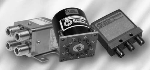
There are two basic types of switches in RF systems: electromechanical and solid state. Electromechanical switches are similar to the wall switch which controls a dining room light. In electromechanical switches, a control signal causes the contact to physically change positions during the switching process. The advantage to electromechanical switches is that they can handle high power RF signals because their insertion loss is very low and their isolation is very high. For this reason, they are quite often used in RF test equipment. In contrast, everything else about electromechanical switches is bad. They are big and heavy, they are slow in switching, and they cost a lot. (Other than that, they're terrific.) Switching speed for an electromechanical switch is in the order of milliseconds (thousandths of a second), which is an eternity in the RF world. Three electromechanical switches are shown in Figure 4-2.
Figure 4-2. Electromechanical switches. Courtesy of Dow-Key Microwave Corp.
Solid State Switches
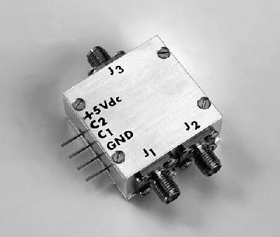
The other type of switch is solid state, which means that at the heart of the switch is some kind of semiconductor device. Unlike electromechanical switches, nothing inside solid state switches actually moves when they switch. This makes them very fast, although they cannot handle the large signals electromechanical switches can. Switching time for solid state switches is in the order of nanoseconds (billionths of a second), which is fast by anybody's measure. A solid state switch is shown in Figure 4-3. Solid state switches are either made from diodes or transistors, which you will learn about in the section on Semiconductors in Chapter 5. Why two choices? Diode switches have lower insertion loss, while switches made from transistors are faster.
Figure 4-3. A solid state switch. Courtesy of JFW Industries, Inc.
Poles and Throws
All RF switches come in different flavors categorized by their number of poles and throws. (It sounds like an Olympic event.) Referring to Figure 4-1, the big dot in the middle of the switch is known as a pole. The pole is the thing to which the "moving" part of the switch is hinged. A switch can have one or more poles. In essence, each pole represents a separate switch within the switch, but different poles within a single switch are not independent. They all switch at the same time.
Throws are all the different positions which the switch can switch to. In Figure 4-1, the switch can be "thrown" to two different positions, A and B, and this switch is therefore a two-throw switch. In fact, the switch in Figure 4-1 is referred to as a single-pole, double-throw switch. A switch can have any (practical) number of throws. A ten-throw switch will have ten different positions it can switch to, labeled A through J. A block diagram of a double-pole, double-throw (DPDT) switch is shown in Figure 4-4. Notice it has two poles (big dots) and each pole has two throws (positions). Ergo double pole, double throw.
Here is an interesting question. If a double-pole, double-throw switch is abbreviated DPDT, how is a single-pole, double-throw switch, like the one shown in Figure 4-1, abbreviated? SPDT. Here is a tricky one. How is a single-pole, four-throw switch abbreviated? SP4T. I think I have beaten this to death, and will therefore assume you can figure out any switch abbreviation you are likely to encounter for the rest of your life, for whatever that's worth.
Figure 4-4. Block diagram of a double-pole, double-throw switch.
Did You Know?
There is actually a type of RF switch called a single-pole, single-throw (SPST), which means the switch has one input (the pole) and only one output (the throw). This invites the question, when the SPST switch is not connected to its one output and an RF signal is applied to the input, where does the signal go? The signal gets reflected, which is why SPST switches are only used in very low power applications.
System Use
Where is a switch used in a RF system? Suppose a cellular phone wants to use its antenna for both transmitting and receiving. The phone could utilize a T/R switch, where the antenna is connected to the N path, the receiver to the A path, and the transmitter to the B path, as shown in Figure 4-5. Furthermore, the antenna could be made to switch to the receiver path every time a signal is coming in (the other person is talking), and it could be made to switch to the transmitter every time a signal is going out (you are talking). Not only would that work very well and eliminate the need for a second antenna, but that is precisely how many cellular phones work.
Figure 4-5. A T/R switch between an antenna, a transmitter, and a receiver.
Any switch which is connected to both a transmitter and receiver, like the one shown in Figure 4-5, is conveniently referred to as a transmit-receive switch, or T/R switch for short.