MATCH
What is Match?
The Meaning of 50 Ohms
Before an RF signal becomes airborne, it spends its existence cruising around on a conductor or inside some component. Every component has an entrance or exit, or both. It is easiest to think of the conductor and the components as parts of a garden hose system with the RF signal as the water inside. If an RF signal is to traverse a conductor and then enter a component, the conductor (garden hose) needs to be connected to the component (a sprinkler). That seems simple enough.
Because engineers run the RF world, no two garden hoses are exactly the same size. So no matter what conductor is connected to what component, some of the RF signal (water) leaks out. (No surprise there.) To make their lives easier, engineers in the RF world have standardized the size of the hose they all agree to use. In this way, a conductor (or component) made by one company will more or less work with a component made by another company—with only a little leaking. If I were actually talking about hoses, the standard size might be specified as "one half inch diameter." Since I'm talking about RF, the standard (hose) size is specified as 50 ohms (named after some famous engineer). Ohms are a measure of impedance, which describes the difficulty the RF signal (water) has in passing through the conductor (hose). There is no real significance to the 50 ohms, other than everyone agrees to make their RF stuff (garden hoses) that size.
The first thing RF engineers want to know, now that they have agreed to this standard size, is how much their hoses will leak when connected to someone else's. This is important to know because the goal is to get a certain amount of RF signal from one conductor or component to another, and if too much of it leaks out, the system will not work right.
VSWR
To measure the amount of leaking, RF engineers coined a term called VSWR (pronounced viz' wär). Technically, VSWR stands for Voltage Standing Wave Ratio, but you'll do yourself a favor if you pretend you never read that. VSWR is a numerical measurement of this thing called match. The better the match, the less the leaking.
The formula for VSWR is complicated, and to make matters worse, its unit of measure is nothing. It has no units. It does, however, have a format of X:1 (read "X to one"), where the bigger the X, the more it leaks (see Table 2-1).
| VSWR | Meaning |
|---|---|
| 1.0:1 | Perfect match, a hose with no leaking, cannot be done. |
| 1.4:1 | Excellent match, very little leaking, often a design goal. |
| 2.0:1 | Good match, acceptable amount of leaking. |
| 10:1 | Horrible match, a result of designing a circuit after reading this book. |
| ∞:1 | As a result of trying to hook up a garden hose to the Lincoln Tunnel.[a] |
[a] For those of you fortunate enough to have avoided calculus, ∞ means infinity.
Return Loss
Because RF engineers refuse to leave well enough alone, one measure of match is not enough. There is another measure of match called return loss, which is measured in, of all things, dB. There is a very straightforward formula for converting from VSWR to dB, but since no one can remember it (including most RF engineers), a conversion chart similar to the one shown in Table 2-2 is used. As you can see, the larger the VSWR, the smaller the return loss.
| VSWR | Return Loss (dB) |
|---|---|
| 1.0:1 | ∞ |
| 1.4:1 | 15.6 |
| 2.0:1 | 9.5 |
| 10:1 | 1.7 |
| ∞:1 | 0 |
Consequences of an Imperfect Match
As much as I enjoy condemning RF engineers for unnecessarily complicating matters, there is a good reason for using the term return loss. When the match is not perfect and the hose leaks, the water (RF) does not actually leak out. In reality, the RF energy heads back down in the direction from which it came. When RF energy starts heading back down in the direction from which it came, it is called reflection (sound familiar?). Since no match is perfect, there is always some RF energy which is reflected. Frequently, the amount of RF energy reflected is small, in which case it goes unnoticed. In situations where the match is poor and a lot of RF energy gets reflected, the device it came from tends to blow up, which is generally how a bad match is discovered.
Did You Know?
There are actually two extreme cases for return loss: a perfect open and a perfect short. A perfect open occurs when someone forgets to connect the rest of the circuit to the output of a component and the RF signal encounters nothing but air. A perfect short occurs when someone lays a screwdriver across a perfect open. In both cases, almost all of the RF energy is reflected and the VSWR approaches ?. Needless to say, this situation should generally be avoided, unless blowing up RF components seems like fun.
Impedance matching
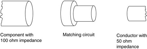
Quite often in the world of RF circuit design an engineer is forced to connect two things (a conductor to a component) with a bad match. For instance, the conductor may have the correct "size" (impedance) of 50 ohms, but the device it is attached to has a size (impedance) of 100 ohms. Connecting these two items as is would result in a bad match, and the circuit would not work very well, as there would be a great deal of power reflected. What do RF engineers do in this situation-after they get done crying? They insert, between the two disparate impedances, a neat little bit of technology called an impedance matching circuit. In the example above, the impedance matching circuit changes the 100 ohm impedance to 50 ohms, so the two items can be properly connected. Figure 2-6 is a graphical representation of an impedance matching circuit.
Figure 2-6. A graphical representation of a matching circuit.

As will be discussed later, impedance matching circuits come in many different varieties, but they all serve the same purpose: to change some RF item's impedance to 50 ohms.
