BROADCASTING
What is Broadcasting?
Characteristics
Broadcasting is nothing more than an RF system which transmits its signal over a "broad" geographic area and is intended for a "broad" audience. (You will never think of broadcasting the same way again.) Broadcasting is classified (in engineering speak) as a one-to-many system, which means there is one transmitter and many receivers. It also means there is no provision for the receiving party to communicate directly with the transmitting party. The three most recognizable broadcast applications are AM radio, FM radio, and television.
All forms of broadcasting in the United States have one thing in common: they have all been sanctioned, by the Federal Communications Commission (FCC), to operate within a very specific bandwidth. (Recall that a bandwidth is a frequency range uniquely defined by its upper and lower frequencies.) The FCC, being the kindhearted organization that it is, divides up these bandwidths into smaller bandwidths called channels, so that different broadcasters can transmit different things loosely referred to as entertainment.
Constraints
To comply with the FCC, broadcasters must operate within three constraints when transmitting their programs. Their first constraint is frequency. As mentioned above, each broadcaster is assigned a channel (frequency range) and can transmit RF energy only within that channel. Of course, to maintain order, everyone else is prohibited from broadcasting in that frequency range. Broadcasting is a perfect example of the need for filters in the output section of a transmitter.
The second constraint a broadcaster must obey is geography. Just because a radio station is granted the right to broadcast in San Francisco does not necessarily give it the right to broadcast in Oakland. In extreme cases, broadcasters have to "tailor" their radiated RF energy to conform to some agreed upon geographic boundary. If you recall from the discussion on antenna patterns, antennas can be designed to radiate RF energy in well-defined geometric patterns. Rarely, however, is there a need for such complex patterns (i.e., no clover leaves). A well positioned circle or oval will frequently do the trick.
Broadcasters place their transmitting antenna at the highest point in their allotted geographic region to ensure a "line of sight" to all the receivers. Suppose for a minute that the highest point (a hill) in a broadcaster's region happens to be at the northernmost point in the region. Further suppose that this northernmost point butts up against the southern edge of some other broadcaster's region (operating at the same frequency). In this situation, the first broadcaster is required to radiate RF energy strictly in the southerly direction (see Figure 6-1 for a visual depiction). By the way, it is entirely possible that the other region's broadcaster (broadcasting at the same frequency) will place their antenna on the same hill. They, of course, are required to transmit only in the northerly direction.
Figure 6-1. Antenna pattern of a broadcaster.

The final constraint a broadcaster must obey, closely related to geography, is power. There is a maximum limit to the amount of RF power a broadcaster can transmit. Two different RF behaviors serve to limit this power. First, as the transmitted power increases, the size of the antenna pattern grows (while the shape and direction stay the same). At some point, the antenna pattern will grow large enough to infringe on an adjacent broadcaster (operating at the same frequency). In Figure 6-1, if the antenna pattern grows too large, it will overlap the broadcast region to the south.
The other unwanted RF behavior, resulting from too much transmitted power, is due to the nature of the RF hardware. Because the output filter in a transmitter isn't perfect, as the RF power coming out of the transmitter within the broadcaster's allotted frequency range increases, so does the power coming out of the transmitter outside of the broadcaster's allotted frequency range. Above a certain power output, this power outside the allotted frequency range begins to interfere with channels in adjacent frequencies (operating in the same geographical region).
The Role of Frequency
Allocation
In the United States, the FCC has defined very specific frequency bands and channel allotments for AM radio, FM radio, and television (see Table 6-1).
| Service | Frequency Band(s) | Channel Allotment |
|---|---|---|
| AM radio | 535–1605 kHz | 10 kHz |
| FM radio | 88–108 MHz | 200 kHz |
| TV (VHF) | 54–72 MHz | 6 MHz |
| TV (VHF) | 76–88 MHz | 6 MHz |
| TV (VHF) | 174–216 MHz | 6 MHz |
| TV (UHF) | 470–890 MHz | 6 MHz |
Your intuition should tell you that the greater the channel allotment (in frequency), the more information that can be broadcast, which is why AM radio, with its 10 kHz allotment, can only broadcast in mono, while FM radio, with its 200 kHz allotment, can broadcast in stereo, and TV, with its 6 MHz allotment, can broadcast video.
A quick look at the AM radio frequency allotment might lead you to the conclusion that, with a total frequency allocation of 1070 kHz (1605-535 kHz) and a channel allotment of 10 kHz, there will be 107 (1070 kHz ? 10 kHz) different channels in the AM band, which is not the case. In practice, radio channels are not mathematically adjacent to one another, but are separated by a small frequency "buffer" to ensure that consecutive channels do not interfere with each other.
Referring again to Table 6-1, the first TV frequency band (54–72 MHz) includes channels 2, 3, and 4. Since each channel is allocated 6 MHz and the total frequency range is only 18 MHz, it appears as though TV channels butt up against one another. In reality, each 6 MHz channel allotment contains a frequency buffer within it. You now have the ability to calculate the 6 MHz frequency allocation of any channel, since the channels are listed in order (by frequency) in Table 6-1. For instance, 76–82 MHz is channel 5, 82–88 MHz is channel 6, and so on. For those of you with too much free time, what frequency range corresponds to channel 51? (I should be mean and not tell you, but I won't.) It's 692–698 MHz, for whatever it's worth.
Did You Know?
You can probably figure out by now why high definition television (HDTV) has taken so long to become reality. All the television sets in the United States are designed to receive an entire program's information in only 6 MHz. HDTV signals contain more information than can be crammed into 6 MHz. (More bandwidth equals more information.) Of course, there is also the infighting among all of the various manufacturers over standards, but that's another story.
Propagation
The way a broadcast signal behaves in the environment has a lot to do with its frequency. Recall from an earlier chapter that when an RF signal, traveling in the air, encounters a solid object (e.g., a building), the signal either gets reflected or absorbed (or both). This behavior makes RF signals what is known as line-of-sight signals, which means that the transmitting antenna must be able to "see" the receiving antenna, without obstruction, for a wireless connection to be made.
Line-of-sight behavior has four implications for anyone trying to receive a television signal over the air. First, there must not be any major obstructions between the transmitting antenna and the television's antenna. Second, the television's antenna must be constantly readjusted as all of the TV stations have their transmitting antennas located in different places. Third, trying to receive an over-the-air television signal in an area with tall buildings will probably result in a signal reception phenomenon called a ghost. A ghost is a double image in a TV's picture and it is very easy to understand. It is simply the result of a television receiving the same signal twice, at slightly different times. What causes a TV to receive the same signal twice? Signal reflections. One signal goes directly from the transmitting antenna to the television. The other signal reflects off of one or more large objects and then makes its way to the television. And since the second signal has farther to travel, it arrives later.
The final implication for line-of-sight signals, and probably the most significant for RF communications, is that to receive an RF signal the receiver must be within 25 miles of the (ground-based) transmitter or else the curvature of the Earth will make reception impossible. (Refer to Figure 6-7 to see a visual depiction of this.) There is one notable exception to this line-of-sight limitation, however. At lower frequencies (less than 30 MHz), signals can travel farther than line of sight by reflecting off the ionosphere (a layer of the Earth's atmosphere). This behavior explains why an AM radio station can occasionally be picked up at night from hundreds of miles away.
Tuning In
The Tuner
The following discussion pertains to television broadcasting, but it applies to AM and FM radio as well. Since all TV signals are only 6 MHz wide, the electronics within the television can only process signals between 0 and 6 MHz. This 6 MHz signal is what I have referred to as the "information" signal in earlier chapters. It contains all of the audio and video information necessary.
This presents a dilemma. The television's internal electronics can only accommodate signals between 0 and 6 MHz, but none of the transmitted signals are between 0 and 6 MHz. They are all at some higher frequency (see Table 6-1). How does the television get these higher frequency transmitted signals down to the frequency (called baseband) which the television's internal electronics can accommodate? It uses a device called a tuner. Before you start thinking that this tuner is some kind of a super-sophisticated piece of RF electronics, realize it is nothing more than a variable filter followed by a mixer (see Figure 6-2).
Figure 6-2. Block diagram of a TV tuner.

The tuner works in a two-step process. First, it selects the desired 6 MHz channel from all of the channels which are out there by adjusting the frequency of the variable bandpass filter to reject all of the unwanted signals, letting only the desired one pass. After which the mixer takes the one signal remaining and downconverts it to the baseband frequency (0-6 MHz). Note, that for the tuner to work properly, the oscillator needs to change its frequency for each different channel.
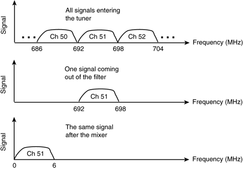
To help you visualize the workings of a tuner, refer to Figure 6-3. The upper graph is a frequency diagram showing all the channels which enter the tuner. After the variable filter, the only channel still remaining is the desired one, channel 51. (I figured you already knew the frequency band.) Of course, at this point the signal is at a frequency which is of no use to the television's electronics. After the mixer, however, channel 51 gets downconverted to baseband, where it is useful. It is at this point where the television's internal electronics take over, process the signal, and produce Seinfeld reruns.
Figure 6-3. The steps in the tuning process.

Television Delivery
Three ways
There are basically three (legal) ways to receive a television signal today: over the air, by cable, or via satellite. While they use completely different methods to relay the signals, all three try to accomplish the same objective: to get as many different 6 MHz channels to your television set as possible. With over-the-air television, the number of 6 MHz channels is limited by the amount of spectrum (frequency bands) allocated by the FCC. This gives both cable and satellite a distinct advantage.
In the case of cable delivery, the cable itself carries signals between the frequencies of zero and approximately 1000 MHz. At 6 MHz per channel, this gives the cable the theoretical ability to carry 166 different channels. The reason it can transmit this many signals is because the signals are trapped within the cable and therefore do not interfere with over-the-air signals.
In the case of satellite TV, the satellite has the ability to deliver a tremendous number of television channels because of something called digital signal processing, which is covered in the section on satellites.
There is actually a fourth method of television delivery, which is a hybrid of the other three, called Multichannel Multipoint Distribution Service (MMDS). MMDS is covered in the section Fixed Wireless Applications in Chapter 7.
Did You Know?
Cable TV providers do not deliver all 166 channels that they theoretically can. The reason they do not is because they have set aside a portion of the cable's frequency band (0-1000 MHz) for RECEIVING signals. Part of the cable's frequency band will be used for two-way communications, which makes it ideal for connecting to the Internet. Of course, since cable service was not originally intended for two-way communications, it may be some time before this service is available everywhere. Stay tuned.
Breaking News
I thought it might be interesting to show the path a television signal travels during a breaking news event—from the event to your TV. In this example, you will be exposed to all of the different roles which wireless communications play in an ordinary, everyday event.
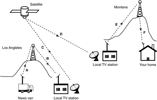
Assume you are in your living room somewhere in Montana and you decide you need some entertainment and so you turn on the television. When you turn it on you discover that you are watching a high-speed police pursuit happening in Los Angeles (a daily occurrence). How has the signal reached your TV (refer to Figure 6-4)?
Figure 6-4. The signal path of a news event.

In this particular example, the news event is being filmed by a camera crew out in the field represented by the news van. The news van needs to get the live feed back to the local television station for processing and retransmission. The news van has the ability to transmit the signal wirelessly back to the TV station. Of course, it cannot send the signal directly back to the station because, more often than not, there are tall buildings and other obstructions interfering with the line of sight. (Remember line of sight?) So the news van sends the signal to the station indirectly, by way of a microwave relay tower (paths A and B in the figure) located at some high point in the city. This form of wireless communication is called point-to-point microwave communication, which is covered in the next chapter on fixed wireless communication.
After the signal reaches the local television station, the program manager decides that the news story is exciting enough even for people in Montana to see. So the local news station transmits the signal up to a satellite (path C), hovering over the United States, and the satellite in turn retransmits the signal back down to the local TV station in Montana (path D). (The satellite doesn't just retransmit the signal to Montana, it retransmits it to every place in the United States, but you will learn more about that in the forthcoming section on Satellite Communications.)
Finally, the local television station in Montana needs to get the signal to you, and since you live way out on a farm, you do not have cable TV. So the local station in Montana uses point-to-point microwave communication to get the signal to a high point in your area (path E). It is at this point where the signal becomes a "broadcast" signal for the first time and gets transmitted to you (path F), and all of your neighbors, of course. The signal you received used six different wireless paths and traveled over 45,000 miles just so you could laugh at some crazy person in Los Angeles. (Where would you be without wireless communications?)
