RF BASICS
Transmitters and Receivers
Electrical energy moves from place to place in one of two ways. It either flows as current along a conductor (a bunch of electrons moving down a metal wire), or it travels in the air as invisible waves. In a typical wireless system, the electrical energy starts out as current flowing along a conductor, gets changed into waves traveling in the air, and then gets changed back into current flowing along a conductor again (see Figure 1-1).
Figure 1-1. Block diagram of a generic wireless system.

In Figure 1-1, the electrical signal flows as current along a conductor (from the left) into the box marked "T." Inside box T, a bunch of stuff happens and out comes essentially the same electrical signal—only this time it is traveling through the air. Box T is known as the transmitter. It turns electrical current into airborne waves. Now traveling at the speed of light, the airborne signal reaches the box marked "R." Inside of the box marked R, some more stuff happens and out pops, you guessed it, the same electrical signal as current flowing along a conductor. Box R is known as the receiver. It turns airborne waves into electrical current.
Did You Know?
Sometimes RF engineers combine a transmitter and a receiver into a single functioning unit. Now what do you suppose they call this ingenious amalgam? A transceiver.
Signals
Analog Signals
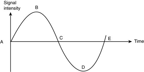
Electrical energy (either current or waves) can actually store information if it is made to vary (in intensity) over time. When electrical energy varies over time in a controlled manner it is called a signal. Signals fall into one of two general categories: analog or digital. For those of you who were unfortunate enough to have suffered through high school trigonometry, you probably remember the sine wave. At the risk of stirring up horrible memories, there is a sine wave shown in Figure 1-2. As time goes by (moving from left to right in Figure 1-2), the intensity of a sine wave grows to some maximum at point B, then back to zero at point C, and on to some minimum value at point D, before finally returning to zero at point E and starting the whole process all over again and again and again.
A sine wave is an example of an analog signal. Whether it is current flowing down a wire or a wave traveling in the air, a sine wave signal varies (in intensity) exactly as shown in Figure 1-2. In the RF world, the intensity of a signal is almost always a measure of power (remember watts?). The number of times a signal goes through a complete up and down cycle (from point[2] A to point E) in one second is the signal's frequency (measured in Hertz and abbreviated Hz). If you find it difficult to remember what Hertz means, every time you hear the word Hertz just replace it with the term "cycles per second." To get an appreciation for how fast these signals go up and down, a 900 MHz (megahertz) signal utilized in cellular telephony, not a particularly high frequency by today's standards, exhibits 900 million ups and downs in a single second. Wow!
[2] Now you know what this is.
Figure 1-2. A sine wave.

Frequency
As mentioned in the introduction, the concept of frequency is key to understanding RF, because all RF stuff is frequency-dependent. That is, it can distinguish between two different signals solely on the basis of their different frequencies. Frequency is what separates one RF signal from another and it is what distinguishes one wireless application from another. Table 1-2 contains a sample of different wireless activities at different frequencies. You may not know what they all are yet, but you can still observe two things. First, notice how many different frequency-dependent applications there are-this is just a small sample—and second, the table is organized in such a way as to give you an appreciation for the difference in magnitude of all the frequencies.
| Frequency in Hertz | Application |
|---|---|
| 60 | Electrical wall outlet |
| 2,000 | The human voice |
| 530,000 | AM radio |
| 54,000,000 | TV channel 2 (VHF) |
| 88,000,000 | FM radio |
| 746,000,000 | TV channel 60 (UHF) |
| 824,000,000 | Cellular phones |
| 1,850,000,000 | PCS phones |
| 2,400,000,000 | Wireless LAN |
| 2,500,000,000 | MMDS |
| 4,200,000,000 | Satellite big dish |
| 9,000,000,000 | Airborne radar |
| 11,700,000,000 | Satellite small dish |
| 28,000,000,000 | LMDS |
| 500,000,000,000,000 | Visible ligh0t |
| 1,000,000,000,000,000,000 | X-Files |
Table 1-3 uses frequency to quantify some terms introduced earlier. These are not strict definitions, but rather general guidelines.
| Term | Frequency Range |
|---|---|
| RF frequency | Less than 1 GHz |
| Microwave frequency | Between 1 GHz and 40 GHz |
| Millimeter wave frequency | Greater than 40 GHz |
Apparently back in the old days, describing a signal's frequency based solely on a number was too simple, so early RF engineers decided to use letters to reference certain frequency ranges called bands. To make matters worse, just when everyone memorized these bands, they went ahead and changed them all. Just by way of entertainment, I have included some of the more popular (old) band designations in Table 1-4. Now when somebody describes a satellite as working in "C-Band," you will at least have an idea what range the signal's frequency is in.
You now know that a signal at 3 GHz can be referred to as either a 3 GHz signal, a microwave signal, or an S-Band signal.
| Band | Frequency Range |
|---|---|
| L-Band | 1.0-2.0 GHz |
| S-Band | 2.0-4.0 GHz |
| C-Band | 4.0-8.0 GHz |
| X-Band | 8.0-12.0 GHz |
| Ku-Band | 12.0-18.0 GHz |
Did You Know?
Somewhere around 1889 a German physicist named Heinrich Hertz actually succeeded in generating the first airborne RF waves in his laboratory. For all his daring and brilliance, the RF engineers of the world have honored him by using his name as the unit of measure for frequency. I guess we're lucky the first RF wave wasn't generated by Heinrich Schmellingstonberger.
Digital Signals
The other type of electrical signal is a digital signal, which is the same type used in a computer. Unlike the (analog) sine wave signal, which varies gradually between its high points and low points, a digital signal is one which varies instantaneously between two electrical values. For all practical purposes, there are no values between the high and low levels in a digital signal. A digital signal is shown in Figure 1-3. Notice there are only two signal levels: up and down (high and low). Digital signals can represent information in the pattern of highs and lows. For instance, a certain pattern of highs and lows can be used to represent your voice as you talk on a cellular phone.
While digital signals are used to "represent" information, they aren't used to "carry" information over the air. Only analog signals (sine waves) are used to carry information "on their backs" as they travel through the air. These analog "carrier" signals can carry either analog or digital "information" signals. The process of combining information signals on top of carrier signals is called modulation, to be discussed later. When an information signal is combined with a carrier signal the result is known as wireless communications, and the analog signal doing the carrying is called RF or the carrier (go figure). An example of analog wireless communications is cellular telephony, the first generation of cellular phones. An example of digital wireless communications is Personal Communication Services (PCS), the second generation of cellular telephony. Both generations use RF to carry different formats of information.
Figure 1-3. A digital signal.

Did You Know?
When a transmitter is always on and the RF signal comes out uninterrupted or continuously, that RF signal is referred to as a continuous wave (CW) RF signal. As you will learn later, there are actually wireless applications in which the transmitter is turned off and on rapidly, and the RF wave is not continuous. You might think that this type of RF signal would be referred to as a "discontinuous" wave RF signal, but it isn't. Just to keep things interesting, RF engineers refer to that type of RF signal as a pulsed RF signal.
You may be wondering which is better—analog or digital wireless communications? The simple answer is it depends, as both approaches have their pluses and minuses. Two things are certain, though. First, digital wireless communications is newer than analog so most wireless communication today (circa 1999) is still analog, and second, digital wireless communication interacts seamlessly with all other digital appliances, like computers. For this reason alone, I think it is safe to say that most, if not all, new wireless communications systems coming on line in the future will be digital.
