ATTENUATORS
Block Diagram
Figure 4-6. Block diagram of a generic attenuator.

The Attenuator's Function
Think of attenuators as anti-amplifiers. A block diagram of a generic attenuator is shown in Figure 4-6. As hard as it is to believe, sometimes in a wireless system the darn signal is just too big, which is where attenuators come in. They make a signal smaller by attenuating it. You may recall from an earlier chapter that attenuation is the result of insertion loss. Attenuation and insertion loss mean the exact same thing. Attenuators allow RF engineers to install a known amount of insertion loss into a circuit.
Visually, a big signal enters the attenuator on the left side and leaves as a smaller signal on the right. Where does the rest of the signal go? You should know that by now: heat, which is why attenuators always come with a maximum power rating. It refers to the greatest amount of RF input power the attenuator can handle without melting. Attenuators can also be represented by the block diagram shown in Figure 4-7.
Figure 4-7. Alternative block diagram of a generic attenuator.

To demonstrate the complex nature of the average RF engineer, there are actually some RF systems in which an amplifier is immediately followed by an attenuator. Talk about indecision. They can't decide whether they want the signal bigger or smaller. There are actually good electrical reasons for doing this, but the explanation is way beyond what you need, and besides, it's just easier to think of RF engineers as complex.
Types of Attenuators
Fixed Attenuators
Attenuators fall into two categories: fixed and variable. Fixed attenuators, as the name implies, cause the signal to experience a fixed amount of loss, measured in dB. Sometimes fixed attenuators are referred to as pads. A typical fixed attenuator might exhibit 3 dB of insertion loss and is therefore referred to as a 3 dB pad. In this case, the signal coming out is half as big as the one going in. (Remember -3 dB is the same as dividing by 2.) A couple of fixed coaxial attenuators are shown in Figure 4-8. Notice that they look just like cylindrical hunk of metal, which is essentially what they are. Fixed attenuators are passive devices.
Figure 4-8. Fixed coaxial attenuators. Courtesy of JFW Industries, Inc.

Voltage Variable Attenuators
The other kind of attenuator is called a variable attenuator. Variable attenuators allow the RF engineer to control the exact amount of attenuation (or insertion loss), at any moment in time, by the use of an external control. There are two different kinds of variable attenuators: voltage variable attenuators (VVA) and digital attenuators, both of which are active devices.
Voltage variable attenuators vary the attenuation over a specified attenuation range and are controlled by a single external control voltage. (I guess that is why they call them voltage variable attenuators.) For instance, a VVA may be specified with an attenuation range from 2 to 30 dB, which means that by varying the control voltage, any value of insertion loss from 2 dB all the way to 30 dB can be obtained. It could even be adjusted to π (Pi) attenuation (3.14 dB) if the need arose. VVAs are used where exact amounts of insertion loss are needed in the system.
Digital attenuators
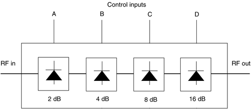
The other type of variable attenuator is a digital attenuator. Unlike the VVA, which has a single input control, digital attenuators have multiple input controls, each controlling a different value of attenuation. It is easiest to think of a digital attenuator as a bunch of fixed attenuators, all in a row, which can either be switched into or out of the circuit at any time. The trick is that each subsequent "fixed" attenuator has twice the attenuation of the previous attenuator. A quick look at Figure 4-9 will clear everything up.
An RF signal enters the digital attenuator at the left and goes through four fixed attenuators before it emerges on the right. Each attenuator which the signal goes through either has the attenuation value shown if it is on, or a value of zero if it is off. Each attenuator is turned on and off with their respective control lines A, B, C, and D. In this way, the total attenuation a signal experiences can range from 0 dB, if all the attenuators are off, to 30 dB, if all the attenuators are on. Note, however, that the attenuation value does not vary continuously from 0 to 30 dB. It cannot take any value between the two extremes, but only those which can be made by adding up various combinations of the four attenuators. For instance, 20 dB of attenuation is possible (by turning off the 2 dB and the 8 dB attenuators and turning on the 4 dB and 16 dB attenuators), but, alas, π dB of attenuation is not. For that you will need a VVA.
Figure 4-9. Block diagram of a digital attenuator.

Digital attenuators can be controlled by the same types of (digital) signals which run around inside a computer, which is why digital attenuators are used when RF engineers want to "program" the amount of attenuation in a circuit. A digital attenuator is shown in Figure 4-10. It cannot be seen from the outside, but inside is a very sophisticated electrical circuit. Also, compare the digital attenuator in Figure 4-10 with the fixed attenuator in Figure 4-8. They look so different, it is hard to believe they are both attenuators.
Figure 4-10. A digital attenuator. Courtesy of Mini-Circuits.

The key performance parameter for all types of attenuators is accuracy. Not only must the attenuation be the exact amount required—whether fixed or variable—but the attenuation must not vary over time, temperature, or anything else.
