MIXERS
Block Diagram
Figure 3-16. Block diagram of a mixer.

Ah, the evil mixer. The mathematics and physics underlying the functioning of a mixer (see Figure 3-16) are so complex, a spreadsheet is required to describe it. Fortunately, it is easy to explain conceptually.
The Mixer's Function
The Mathematics
The purpose of a mixer is to change the frequency of a signal while hopefully keeping everything else about the signal the same. Visually, one signal enters the mixer at the left side at one particular frequency (f1), while another signal enters the bottom of the mixer at a second frequency (f2), and what comes out of the right side are two different signals. One signal has a frequency equal to the sum of the two other frequencies (f1 + f2) and the second signal has a frequency equal to the difference between the other two frequencies (f1 − f2). A simple example will clear everything up (see Example 3-1).
This raises three questions. 1) Why does a signal's frequency need to be changed? 2) How does the fact that there are now two signals get resolved? 3) What makes mixers evil?
Example 3-1 Mixer mathematics.
Two signals are going into a mixer. One signal has a frequency of 500 MHz and the other signal has a frequency of 400 MHz. What are the frequencies of the two signals coming out of the mixer?
The first frequency can be calculated by adding the two numbers.
![]()
The second frequency can be calculated by subtracting the two numbers.
![]()
The two signals coming out of the mixer have frequencies of 900 MHz and 100 MHz.
Changing Frequencies
First, a signal's frequency must be changed because the signals which you and I encounter in everyday life are at different frequencies from the signals used to carry information over the air. For instance, when you speak you create sound waves in the neighborhood of 2 kHz (2000 Hertz). However, if you hope to talk on a cellular phone, the frequency of your voice (2 kHz) needs to be changed to the frequency used in cellular communications (900 MHz). In order to change the frequency of a human voice to that of the cellular carrier, one or more mixers is required.
Second, the two signals coming out of the mixer are dealt with by getting rid of the unwanted one. In the example above, if the desired signal is the 900 MHz signal, then the 100 MHz signal is eliminated. Now for the Final Jeopardy question of the day, how is the 100 MHz signal eliminated? Do do do do do do do, do do do do doo-da do do do do. With a filter, which is why there is always a filter right after a mixer, because the mixer puts out two signals and the filter gets rid of the one that isn't needed. This stuff all makes sense, if you give it a chance.
And finally, why are mixers evil? If mixers worked exactly as described above they wouldn't be evil. As you have already learned, in the world of RF, things aren't that simple. In reality, when two signals are fed into a mixer what comes out is not just two nice clean signals. Dozens of signals come out, at all different frequencies, which drive RF engineers crazy. (Come to think of it, that is one of the mixer's greatest benefits.) These unwanted signals are loosely referred to in engineering parlance as noise. Noise in an RF system is either a signal at a frequency which is unwanted, or an imperfection in the RF signal which is wanted. Mixers are notorious for injecting noise into RF systems, which is another reason why they are followed by a filter.
Other Names for Mixers
It needs to be pointed out that mixers are sometimes referred to as upconverters or downconverters. If the mixer is part of a receiver, then it is a downconverter. If it is part of the transmitter, well you can figure out the rest.
How Mixers Work
Three Ports
In an effort to expand your already vast RF vocabulary, the two inputs and one output (called ports) in a mixer are referred to as the RF, LO, and IF. The RF is the higher frequency signal which was previously referred to as the carrier (900 MHz in the previous example). The IF, or intermediate frequency, is the lower frequency signal, and the LO will be explained in the next chapter. As you might suspect, the RF, IF, and LO ports have very limited frequency ranges over which they work. Trying to operate a mixer outside one of its ports' frequency range will result in poor electrical performance. And, just like every other RF component, the wider the frequency range of the three ports, the more the mixer costs and the worse its performance is. Every attempt is made by RF engineers designing with mixers to choose the ones with the narrowest possible frequency ranges which will accomplish the task. A typical mixer is shown in Figure 3-17 (not much to look at). Make a note that the mixer does, in fact, have three ports.
There are both active mixers and passive mixers, but if the truth be told, 95% of all mixers used are passive. While active mixers do have gain, which is generally a good thing, the rest of the active mixer's performance parameters stink, so hardly anyone uses them.
Conversion Loss
Like all passive components, passive mixers exhibit insertion loss. Of course, RF engineers do not call it insertion loss, which would be too easy. Insertion loss in a mixer is called conversion loss (CL), just to be different. Conversion loss is one of the two most important parameters of a passive mixer. The lower the CL, the better. The other key parameter of a passive mixer is noise figure (NF). (Remember noise figure?) You thought only amplifiers have an NF. Not true. And just like LNAs, the lower the NF in a mixer, the better. Also, as indicated above, the wider the frequency ranges of the RF, IF, and LO ports, the worse will be the CL and the NF, and if you can understand this sentence with all its acronyms, you have truly grasped mixer terminology.
Figure 3-17. A mixer. Courtesy of Mini-Circuits

Mixer Configurations
Two-Stage Mixers
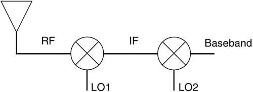
Here is one last attempt to complicate things. If there are two mixers in a transmitter or receiver, which is usually the case, the signal between them is the IF and the lowest frequency signal is referred to as the baseband signal (see Figure 3-18).
Figure 3-18. Block diagram of a two-stage mixer in a receiver.

Note that the baseband is just a lower frequency version of the RF signal. It still has the "information" signal riding on top of it. A complete receiver can be thought of as performing two functions. The first function is to lower the frequency of the carrier, and the second function is to strip off the "information" signal from the baseband signal. The second function is discussed in more detail in the section on Modulation. Of course, both of these steps also happen in the transmitter, only in the opposite order.
Did You Know?
When a receiver uses two mixers in a row, as shown in Figure 3-18, it is referred to as a superheterodyne receiver. Knowing that, plus two nickels, will get you a dime.
Mixer Types
Just to mention in passing, you should know that mixers come in three flavors: single-ended, double-balanced, and triple-balanced. These distinctions have to do with how the mixers are built internally and, for the sake of this book, have no effect on a mixer's function. All this is a long-winded way of saying when you hear any of the mixer descriptions mentioned above, ignore them and just think to yourself, mixer.
Frequency Doublers
There is another component which is closely related to the mixer: the frequency doubler. At the risk of insulting you, the output frequency of a frequency doubler is twice that of its input. Remember how mixers produce all sorts of unwanted signals at different frequencies? Frequency doublers use this behavior to double a signals' frequency. Enough said.
