
![]()
Project 1: Good Evening, Mr. Bond: Your Secret Panel
We’re in at the deep end with this project. There is some fairly complicated mechanical making and woodwork in this project. There is no reason at all why you should do this project first, so if it seems a bit daunting and you want to build up to it, have a look at some of the simpler projects first.
This project celebrates that old favorite of certain movie and story genres—the secret panel —the kind of panel that unexpectedly opens in the wood paneling of a classic country house library when you touch the contacts embedded in both eyes of a portrait on the wall, or turn the head of an apparently immobile statue! But what’s behind the panel . . .? Well, that’s rather up to you.
A Life Ruined by Movies and TV
I admit it. When I was younger, I watched way too much Batman, Thunderbirds, Scooby Doo, Secret Service movies, and body-in-the-library mysteries. Mystery and secrets are the themes that tie these entertainments together. All of them (at one time or another) featured a secret door or a secret panel, inside which was variously concealed an underground silo full of advanced technology, a crazy janitor named Jameson, a control panel with switches marked “Launch Missiles,” or a bloodstained murder weapon. I always wanted a reason to have secret panel in my own house, but I always struggled to think of a use for it in my own real life.
The shameful truth is that, if I’m honest, I still struggle to think of what I am really going to use it for—but the good news is that now that I have built my “secret panel,” I will finally have to give it some serious thought!
Making It Real
Oh boy, there are so many ways to do this, but the most obvious ones are not necessarily the best. Let’s start by stating the basic requirements, which are these:
- A small panel is to be dragged about 9–12 inches and back again by using an electric motor under the control of an MCU.
- The panel must slide smoothly (but not too quickly, you want to savor the moment of movement and revelation) between its open and closed positions.
- The panel must always return to the same open and closed positions; these positions cannot vary by more than very small amounts.
- The panel must be of a size that is easily concealed, or it must blend in as much as possible with whatever it is set into.
- The panel must only be activated by a concealed activation method (a hidden button, etc.).
- The secret panel assembly as a whole must operate in vertical or horizontal orientation. It must be able to be set in a wall or into a desk.
- The panel should be safe—that is, its mechanism should not be strong enough to cut off somebody’s finger!
- The panel, when it opens, must reveal something utterly astounding!
I’m afraid that although I have some ideas, the revelation is mostly going to be up to you!
My first attempt at this project involved a convoluted system of pulleys and used fireline (a very strong plastic thread that’s used for jewelry and fishing line) which allowed a single motor with two spools to push and pull the panel into position (see Figure 1-1).
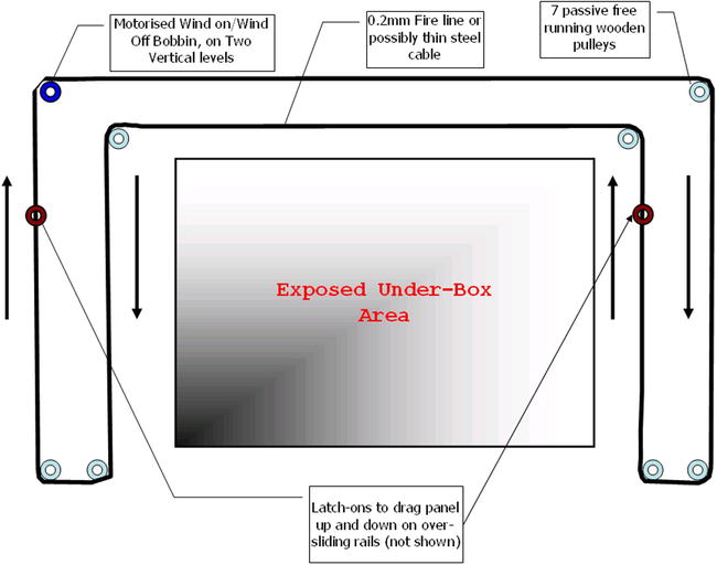
Figure 1-1. Thread and pulley version (failed)
This worked pretty well, but only for about a day! It turns out that fireline, at least for this use, stretches slightly and with a fairly long run like this, it meant that the push-pull motor arrangement (top left in the diagram) was not viable since the thread got progressively longer and thus looser. After a day or so of use, it got slack enough to jump off the winding spools and wreck the whole scheme!
Next, I tried using some steel garden wire in place of the fireline, but this idea was a nonstarter with the motors that I had on hand. Steel garden wire is not very flexible, and when used with the required number of right-angled turns, it exerted more drag than the motor could handle. With a more powerful motor and a slightly thinner wire, this idea might work. The other problem that I became aware of, before I gave up on this approach, was that the wooden pulleys (I used the same arrangement as described in the Solenoid leverage example in Chapter 4 of Practical AVR Microcontrollers [Apress, 2012]) started to chew through the wooden mount and go off the true when subjected to the force required. So, no prize for this approach! I have no doubt that with a metal frame, some metal pulleys with smooth bearings, and a powerful motor, it probably could work, but it would get pretty expensive, pretty fast!
My next idea was a simple one. The panel is pulled open by the motor, again just using fireline threads. Then, when the motor turns the other way, a counterbalancing weight pulls the panel from the other end to return it to the closed position. Since, in this arrangement, the fireline is not pushing and pulling, it doesn’t matter if it stretches a little. However, this scheme would presuppose that the panel will be mounted in a place where there would be space for this counterbalance to travel up and down, and, actually, I struggled to envisage many installation scenarios where that might be true. Similarly, I tried out but discounted the idea of return springs; the kind of return springs you would need would be quite long and might be hard to fit into the overall mechanism space. Also, you would have to tether the panel to the springs with something lightweight but strong, and if that something stretched . . . then again you would encounter the precision problem.
Thinking Again
The absolutely ideal solution would be a helical spring. This is the kind of rotary spring that’s built into extensible measuring tapes, or extensible “queue barriers,” the kind you often see in stores, museums, or stadiums. However, I tried using the helical spring from a measuring tape (the most obvious low-cost source of such a spring) and found that it’s not nearly strong enough for this purpose. Springs with the kind of return force required are meant for use in things like elevator car doors, and they come with a very unattractive price tag of several hundred dollars. Curses! Foiled again!
Next, I tried some steel-threaded rod. This stuff can be bought in almost any hardware store and is used for a variety of things in the building trade. It’s also pretty cheap. If you put a nut on the threaded rod and turn the rod while holding the nut still, the nut slowly moves up or down. You do have to spin the rod fairly fast to get a decent speed of movement—but the amount of force required to turn the rod is actually quite small due to the immense amount of leverage involved. So this idea was promising.
After a search on the Internet, I found that many model makers and woodworking sources have a “threaded insert,” which you can put inside a block of wood and which presents an internal thread suitable for use with a threaded rod. Figure 1-2 shows one of these.
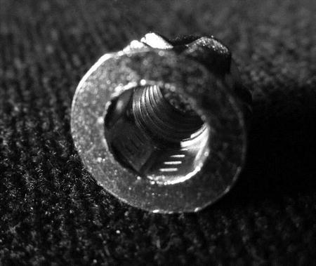
Figure 1-2. Threaded insert
This insert in Figure 1-2 has a metric M6 thread through the center—but you can get these in various metric or imperial sizes from the following sources:
- www.amazon.com (United States). Search for “threaded insert” in “Industrial and scientific” category.
- www.modelfixings.co.uk (UK).
On the outside, the insert has a coarse thread that can chew its way into a suitably sized hole through a wooden block and an Allen key head to help you screw it into the wood.
My idea was to use a couple of these fixed onto some small wood blocks on each side of the sliding panel. I built this idea up, but it has two crucial drawbacks. First, it’s far, far too slow; I started with a 60 rpm motor and the panel movement was positively glacial! I tried using a 500 rpm motor, but the panel still moved too slowly. Worse (and this is the second problem), when you spin the threaded rods at that speed you really do need proper metal ball-race bearings at each end. Using holes in the wood at each end of the rod really doesn’t work when those spin speeds are involved. Since these threaded rods are almost never quite straight, they generate vibration when spun at any speed—especially at the lengths required here; in short, the mechanism would shake itself apart in no time. The threads on the standard rods are too fine.
Again, there is a fix for this. You could use “Acme” threaded rods (or the similar “trapezoidal threaded” rods) and nuts. These kind of threads are much more suitable and high precision. The rods are usually thicker and the threads are more coarse, but deeper. These are intended for exactly this kind of use. If you look at the thread on a bench vise or a manual car jack, you’ll likely find one of these threads in use there. The problem is that if you elect to use one of these threads you increase the cost of the project by something like an order of magnitude—they are not cheap. You’d also have to find a source of Acme or Trapezoidal threaded inserts—which I have not yet managed to do. So, this approach comes close, but it seems to run into the sand on details and cost.
Racking Up a Success
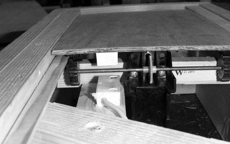
Finally, I settled on something intended for robotics or model vehicle use. There are lots of gearboxes made for driving wheeled vehicles. Here, a motor/gearbox assembly is mounted in a robot, or a model vehicle, and provides controlled drive to its wheels. If we hold such an assembly captive in a frame, and fit it with cogs instead of wheels, it can drag a panel back and forth. This is effectively a rack-and-pinion system. The panel is fitted with tracks on its underside that mesh with the cogs, as in Figure 1-3.
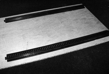
Figure 1-3. Sliding panel underside
Many suitable gearboxes and motor assemblies are available:
- www.pololu.com/catalog/category/34 (United States and global).
Or, for a very low-cost example—the one I used, in fact:
You can get the rack parts from
- www.robotmarketplace.com (various products—search for rack).
- www.technobots.co.uk (search for part numbers 4600-024 and 4600-110).
The exact details of the woodwork part of this project will vary. The essential requirement is to make the panel that you want to slide and build everything else around it. The panel should be as symmetrical as you can make it, it should be as smooth and flat as you can make it, and it should be fairly lightweight. If the panel surface will be visible, it will have to match the surrounding surface if it’s not to stick out like a sore thumb. If you’re lucky enough to have a wood-paneled room (or, even better, be building one), you might be able to find a way to set your project into the paneling—everybody’s idea of a classic secret panel.
Probably (as in my prototype), it will have to be of a size that can easily hide behind a “concealer,” which might be a picture, a mirror, or a drape or wall hanging of some kind. If it’s set into a horizontal surface like a desk, worktop, or shelf, it might be concealed beneath a mouse mat, a desktop CD-ROM, a blotting pad, a writing surface, an “in tray,” a clock, a large ornament, a small loudspeaker, a desk tidy—really the possibilities are endless.
The sticking point is usually going to be space; you’ll need space behind or under your secret panel to allow for the mechanism and the concealed compartment. Hollowing out such a space in a brick or concrete wall can be done but is problematic. There may not be enough space back there for what you need. However, it can be a lot easier to accommodate in a less solid structure, such as the following:
- A drywall.
- A large walk-in closet or an enclosed shelving unit.
- The kind of custom cabinetry often made for a home-theatre setup.
- A desk or work surface.
Of course, always bear in mind that your panel doesn’t have to be a sliding one (although that’s what we’re building here). It could be a flip-open panel that looks like a picture or a decorative molding; one that flips open when you activate a solenoid via your AVR.
Once you have your panel made, you need to design a frame. The frame must
- Be rigid enough to remain square and not distort when you mount it behind something else.
- Be suitable for fitting a backbox or under-box onto.
- Be suitable for mounting the motor on.
- Provide a slideway for the panel.
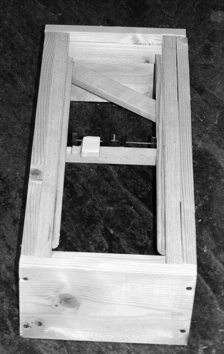
The photo sequence in Figures 1-4 through 1-6 shows my version of the project parts; luckily I had a drywall that I could play around with so I was able to cut a hole, right through into a closet on the other side. This meant that I could keep everything hidden from view. I’ll go into some of these parts in more detail later in the chapter.
![]() Caution Are you making a permanent version of this project for serious use? It’s important to ensure that if the panel jams, its fuse blows, or its power supply fails, you can still access the mechanism and electronics in some way. You don’t want to have to smash the thing apart if somebody fools around with it and blows the fuse. It’s meant to be secure by virtue of being secret; it’s not meant to be impregnable!
Caution Are you making a permanent version of this project for serious use? It’s important to ensure that if the panel jams, its fuse blows, or its power supply fails, you can still access the mechanism and electronics in some way. You don’t want to have to smash the thing apart if somebody fools around with it and blows the fuse. It’s meant to be secure by virtue of being secret; it’s not meant to be impregnable!
|
Figure 1-4 shows the frame for my prototype sliding panel. |
|
In Figure 1-5 you can see the panel set into the slideway and how the tracks on its underside mesh with the cogs on the axle. |
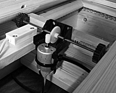
|
Here’s another view of the drive mechanism. The sliding panel has been removed; you can now see the concealed compartment behind the motor assembly (see “The Secret Compartment” below for details). |
Of course, it’s pointless to have a secret panel if you have an obvious activation button for it. So finding a nonobvious method of activating your secret panel is quite important.
You could just have a hidden keypad that sits alongside the panel, but that’s a bit, well, tedious. In all the best movies, it just takes a finger jab at a cunningly concealed button to make the panel slide or flip open. So, where can we hide the button? I investigated several possibilities.
- Inside a figurine of “The Stig” (the mystery test driver from the BBC TV series “Top Gear”). This started out life as a novelty gift. It contained shower gel. When it was empty I decided not to throw it away but to keep it as a shelf ornament. Actually, though, having washed it out, it occurred to me that if I could thread a pair of wires through it and mount a tiny push button under Stig’s removable head (the lid for the shower gel)—well, that might work!
- Inside a clock. I have a carriage clock that has its own secret compartment behind the face. How about hiding the button in there? The clock seldom needs to move, so hiding the wires is pretty easy.
- Inside a hollow book, the kind sold as a “security safe” or “book safe” on numerous web sites and stores. It’s an old idea, but still a good one. The problem is the trailing wires. You could go for the additional complication of battery operation and a wireless sender inside the fake book; however, if you’re really that serious about security, this would have to send an encrypted activation signal. Of course, you’d also need a receiver and decoding software at the AVR board end of things.
Without resorting to wireless, you’re going to have wires trailing when you pull the book off the shelf. You could do it another way; use a piece of reflective foil on the back of the book and a reflective sensor built into the back of the book case that recognizes when the book is removed, but that makes you dependent upon several assumptions, such as that the book will always be in the same position and that when the room is in darkness the light doesn’t give away the position of the device, and so on. So, the hollow book idea is do-able, but it has a lot of snags to work out.
- A pair of touch contacts disguised as screw heads or random furniture features. I actually tried this with an old chair that had its covering fixed on with metal furniture studs. I tried wiring one stud into one of the AVR’s analog inputs and the other to ground. The idea is that when you use one finger from each hand to bridge between the two, the panel opens. Unfortunately, as you can’t use adjacent studs which might be discovered accidentally by anyone sitting on the chair, the cable lengths get a little too long and you get a lot of noise which can result in random activations even just because somebody walks past the chair. I also feared that it might not be long before static electricity might zap the AVR input. Somebody in nylon clothing shuffling around on a chair can probably generate quite a lot of static and that static might well want to escape through the AVR input. It might be possible to resolve these issues with a different electrical arrangement and smarter discriminating software, but it seemed like a long job and, well, there were other, more attractive, alternatives.
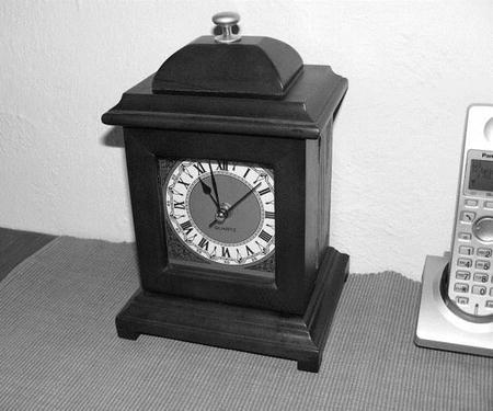
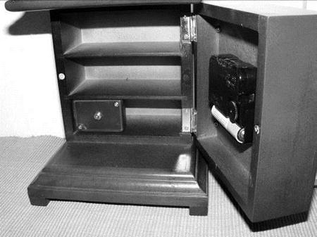
In the end, I built the shower gel Stig version and the clock version. Unfortunately, the owners of the Stig copyright were unable to give us permission to use pictures of that version, but take it from me, it looks very cool! The clock version (which we can show in a picture) is also pretty good. Figures 1-7 and 1-8 show the clock normally and with secret frontage opened to reveal the push-button box.
|
An unassuming modern-day repro carriage clock. |
|
First, it has an opening front which reveals a set of tiny storage shelves. |
I briefly considered the idea of using some distance sensors to allow the software to know the panel position. However, the cost of using these is not really justified here. All we really need is a momentary switch closure when the panel reaches its fully open or fully closed position. This could be done with mechanical switches with long actuation arms—as covered in “Sensing Movement” in Chapter 4 of Practical AVR Microcontrollers (Apress, 2012). However, I was not keen on this approach because
- I wanted to avoid anything that might impede the panel’s movement, or have the potential to do so as the mechanism wears.
- Mounting physical switches on the prototype frame was actually going to be problematic.
In the end I went for a contactless approach. I found some small magnetic security sensors which used encapsulated reed switches that can detect a magnet being within about 1/2" (12 mm) of them. These products are made to be used as simple door or window sensors in alarms and security systems.
All I had to do was mount a small magnet on the lower—unseen—side of the sliding panel and mount one reed switch at the fully open point and another at the fully closed point of the panel’s travel. The software is written such that it continually polls the switches whenever the panel is in motion, so it won’t miss the switches being activated as the magnet passes.
These small magnet/switch products are widely available, for example
- www.amazon.com (United States) search for “magnetic window alarm sensor”—you’ll find lots of examples.
- www.maplin.co.uk (UK)—search for stock number MM08, or look on B&Q web site, etc.
When the sliding panel has slid gracefully aside, it will reveal the secret compartment. This is the nub of the whole thing—the reason for doing it; I think that means it deserves to have some magic about it!
I built a small wooden box sized to fit snugly inside the frame. I made quite a wide brim for it out of wide flat wood. Underneath the brim I put two flexible LED strips (blue ones) and fixed them on with twists of garden wire drilled through holes in the side of the box (similar to the technique used to fix the LED strips in the waterfall passageway light project).
When seen from straight on (as it normally would be once installed), you can’t see the LED strips—you just see a circle of blue light fading up (thanks to the software) as the panel opens. It looks superb. Figures 1-9 and 1-10 show the backbox made and ready to be installed in the frame, with LED strips installed.
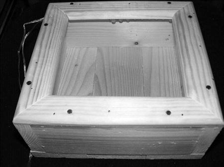
Figure 1-9. The compartment before installing in the frame
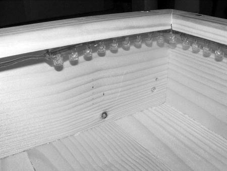
Figure 1-10. The compartment showing LED strip
Obviously if you’re building one of these for yourself the size of your backbox or under-box is going to depend on how much space you have and the size of the frame. Finally, with the backbox installed in the frame, the motor fitted, and the panel in place and ready to slide we have the mechanical side of things settled; it’s time to look at the electronics.
Figure 1-11 shows the circuit diagram for the electronics side of the secret panel project.
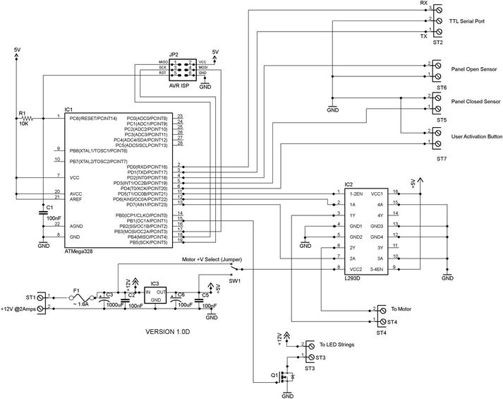
Figure 1-11. Secret panel circuit diagram
In my version of this project a +12-volt supply is needed for the LEDs and the +5V is derived from that using a 7805 voltage regulator. That regulator should be fitted with a heatsink. If you are using a LED string product that needs only +5V (as many SMD (surface mount device) LED strings do) and your motor is happy running on +5V, then you can simplify this design quite a lot.
![]() Caution It’s very important to make sure that you use a fuse—as indicated in the Figure 1-11—nasty things can happen if something goes wrong and there is no fuse to blow! This is especially important in any device with moving parts where fingers may get caught.
Caution It’s very important to make sure that you use a fuse—as indicated in the Figure 1-11—nasty things can happen if something goes wrong and there is no fuse to blow! This is especially important in any device with moving parts where fingers may get caught.
Whichever side of the power supply (12V or +5V) is running, the motor should have C3 on it. This is a fairly large capacitor, which is there to counteract the motor’s startup demand. It’s shown on the +12V side on the diagram, but swap around C3 and C6 if you’re running your motor from +5V.
The electronics for this project consists of two chips, one voltage regulator, and one transistor. The first chip is of course our trusty ATmega328 (you could easily use ATmega168 instead if you wanted to—the code for this project is quite small). As with all our projects, the AVR has to be running at 8 MHz (as detailed in Chapter 3 of Practical AVR Microcontrollers [Apress, 2012]). We of course have our usual ISP jack for programming the AVR and the reset RC network across the RESET pin and we have the TTL level serial port. If you’re building the circuit on the test bed breadboard (which is what I did) then you’ll already have all these items. If you’re building this on a solder board or some other way, you’ll need to provide these things.
The second chip is an L293D chip; this was the one used in Chapter 4 of Practical AVR Microcontrollers (Apress, 2012) when we looked at “H” switches and push-pull drivers for use with stepper motors. Here, though, we’re only using a single coil motor so we’re only using half of the chip—we disable the other half. The chip can drive a motor up to about 600 ma, so you’ll need to make sure that your motor is not going to overload it. The L293 does feature over current protection, though, so if you are in any doubt, try out your motor and see what happens.
Three I/O lines go from the MCU to the L293D
- AVR pin 11 (Arduino digital pin 5) connects to the enable input we are using (pin 1). The AVR has to make this pin HIGH for the L293D to be enabled.
- AVR pin 12 and pin 13 (Arduino digital pins 6 and 7, respectively) are used to set the polarity of the power going to the motor (i.e., which of the “Y” outputs is pushing and which is pulling). If they are both set to LOW then the motor gets no power. The software PWM pulses whichever is the positive lead to make the motor ramp up. The enable pin overrides these signals.
Pin 8 of the LS293D is the motor supply pin. As shown in the diagram in Figure 1-11, you can use a simple wire jumper to provide power from +5 volts or +12 volts, depending on the voltage your motor requires. The L293D spec says you can use up to +36V as the motor supply. The unused half of the L293D simply has its inputs tied to ground. We don’t need to use snubber diodes or any current limiting; the chip has all that built in.
The AVR’s pin 15 (Arduino digital pin 9) interfaces to the MOSFET, and that drives the LED strings. The MOSFET used is over spec for this purpose, which means that you could add a lot more LED strings to your own creation.
The two limit switches (in the software these are called PANEL_FULLY_OPEN and PANEL_FULLY_CLOSED) connect to AVR pins 4 and 5 (Arduino digital pins 2 and 3, respectively). These are simple magnet-operated reed switches which connect to ground when the magnet attached to the moving panel passes near them. The internal AVR 20K pull-ups are enabled on these pins, so there is no need for external pull-up resistors.
Finally, the user’s push button (wired across from inside the clock—as shown earlier) interfaces via AVR pin 6 (Arduino digital pin 4). This is, again, a simple connection to ground with a pull-up enabled on the AVR. The software only activates this push button when it is released; this is to prevent a user from holding it down to make the panel cycle continuously, which it is not meant to do (the L293D would go over temperature and shut down, for one thing).
That’s it for the electronics, all the external connections in the prototype are—as shown—made by screw connectors, but you could use something else if you wanted to. I used PCB mounting screw connectors with fairly long pins.
Sliding Panel Electronics Troubleshooting
You can find out quite a lot by connecting to the TTL level serial port (see Chapter 3 of Practical AVR Microcontrollers [Apress, 2012] for details) because the software outputs quite a few messages as it goes about its work. It will indicate each operation as it starts and ends; it also indicates fault conditions and sensor events.
You’ll find that the reed switches used as limit detectors do tend to bounce quite a lot. The software counteracts this bounce by reacting to the first “sighting” of the limit switch it is expecting to close. For example, if the software is commanding the panel to close, it continuously monitors the fully closed sensor and reacts to the first pulse it sees from the PANEL_FULLY_CLOSED switch and then stops looking at that switch.
If you are having problems, there is provision in the software for fitting a “fault” LED provides additional assistance (it’s not shown on the circuit diagram in Figure 1-11 because I never needed it and hopefully you won’t either). If you want additional indication of what the MCU is doing, attach an LED with its + lead to AVR pin 14 (Arduino digital pin 8) and its negative lead through a 330R resistor to ground. When this LED lights up it means that a panel transit has taken too long. During building you’d see messages about this on the serial channel. However, once installed and working it could be handy to have an LED indicator showing there is a problem.
If the LED comes on (or you see a panel transit time-out message on the serial channel) it could be caused by several things.
- The panel is stuck due to some blockage or mechanical jam.
- You’re using a slower motor than I did (in which case, adjust the time-out value MAX_PANEL_MOVE_TIME).
- You’ve adjusted the parameters of the ramp-up function within the software which has altered the total transit time of the motor.
In most cases you’ll know if the mechanism jams; it will make a ghastly noise. If it used to work but now times out, maybe the panel slides need cleaning and are slowing down the panel movement? In my design the panel is held captive in its slides by the wall or surface onto which you fix it. If the surface has warped slightly so that it’s squeezing the panel and restricting its ease of movement, that can easily cause a problem.
If you’re having problems with the electronics of a newly built panel it may be because your motor has different startup characteristics than the one I used and it’s spiking your power supply or momentarily dragging it down (if the power supply is not providing enough power). Such a problem can have many negative effects, such as a complete software restart whenever the motor is commanded to start, or garbled text coming out of the TTL serial port, or the motor starting for a moment then stopping again.
If you do suspect that the motor is causing problems, try modifying the rampPanelMotorUp function within the software to make a softer, more gradual, start.
If the problem remains, in many cases the answer will be to add a larger reservoir capacitor across the supply rail supplying the motor. Try duplicating the existing reservoir capacitor (in my design this would be C3) to see if that fixes the problem, or at least changes it a little which would indicate that you’re on the right track and just need to increase the capacitor value. Also, try adding some duplicates of C2 and C5, placing them near the L293D. If you can, try a different power supply which offers a little more amperage, or try a different motor.
The software is—downloadable from this book’s web site (www.apress.com/9781430244462). The following is a code walk through the main functions of the program.
|
Function |
Commentary |
|---|---|
|
Declarations Header Section (args: none) |
In this initial section the Arduino pin numbers for the various external connections are defined (see previous text) and various constants are declared. Of special interest are:
|
|
setup() args: None |
The setup() function initializes all the I/O pins as required (including enabling pull-up resistors for inputs) and initializes the serial port. It then collects the initial sensor states. Then, it fades the LED strings up and down to provide a visual verification that they are working. Finally, if the panel seems to be open, it is closed. |
|
loop() args: None |
The main loop() function of this program is pretty simple. If the user button has not been pressed then it just updates the limit switch states—and that’s it! If the user switch has been pressed then it checks to see if the panel looks as if it is closed; if so, it opens it. In any other case (the panel is open, or neither sensor is active) the panel is closed. All user button press actions result in a message going out to the serial port. |
|
closePanel() args: ledFaderStart AND openPanel() args: ledFaderStart |
These functions command the motor to ramp up in the required direction to open or close the panel. They then wait until either the appropriate sensor is activated (e.g., closePanel waits for the PANEL_FULLY_CLOSED sensor to be hit) or a time-out occurs. The LED strings are faded in or out while waiting for the panel to complete its transit. The LEDs are left fully on (panel open) or off (panel closed) at the end of the function. The motor is always turned off when these functions end. LED fading doesn’t start until ledFaderStart milliseconds after the function is called. This allows an adjustment point to allow fading and panel movement to be better synced when using different motors and processors. Messages are issued to the serial port, and the failStateLed pin is put ON in the case of a time-out. |
|
rampPanelMotorUp() args: pwmLead |
This function does a feathered start on the motor. Electrically and mechanically, this works a lot better than just putting full power on the motor straight away, and in this application it looks classier! The function takes one argument which is pwmLead. As detailed earlier in this chapter (see “The Electronics” section earlier.) there are two control lines into the motor driver. By setting one or other of these to low and the other to high you control the polarity of the power supplied to the motor. pwmLead in this function specifies which of the possible two Arduino pin numbers is to be the positive. The polarity setup is actually done by the setMotorControls() support function. We initially increase the PWM pulses into the motor quite gently but more aggressively as the PWM pulses get longer. You’ll probably need to tune the point at which this happens (as per comment in the code) to best suit your chosen motor. |
|
motorOff() args: None |
Sets both motor leads to LOW so that no power flows through the motor. Used to stop the motor quickly when the panel movement is over. As an alternative to this you could also add a rampPanelMotorDown() function which slow-stops the panel, but that depends on how much momentum your mechanical components have and whether they might overshoot too badly. |
|
progressLedPwm() args: fadingUp |
This function progresses a LED string fade up or down (the Boolean argument fadingUp indicates which type of activity is in progress). In order to make sure that fading is pretty and doesn’t happen too fast, we use a ledDelayCtr (a static variable). This effectively counts how many times this function is called and only does a fade step every LED_DELAY calls. |
|
Various Others |
The other remaining functions are very small and self-explanatory. |
All Together Now!
So, finally, it is time to put it all together. I made a hole in the drywall. On the panel side that was just large enough to let the secret compartment become visible. On the other side, it had to be big enough to mount the frame into the wall, so it was quite a large hole (but inside the closet mentioned earlier). I put a frame around the hole on the front side and secured the frame assembly on the rear side mounted so that the secret compartment lined up to be visible. After making sure that the panel could move back and forth freely, which involved a tedious amount of smoothing of the rear face of the drywall (which had to be dead flat to ensure that the panel stayed trapped in its slide run and could not jump out), it finally all came together. I used a picture as the concealer to hide the panel under normal circumstances.
The sequence in Figures 1-12 through 1-15 shows the final installation.
|
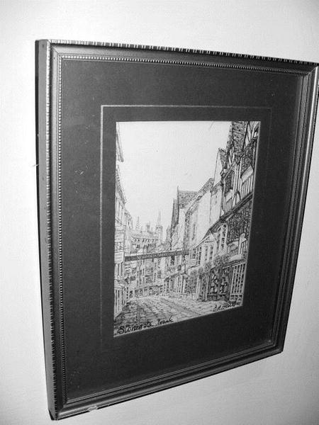
A picture hanging on the drywall. |
|
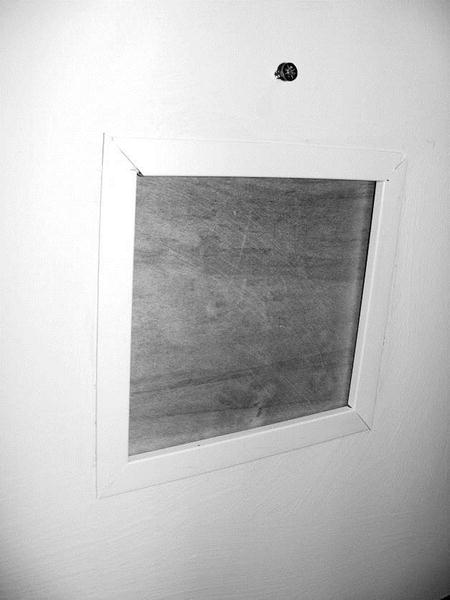
Behind the picture, a framed opening, blocked by a wooden panel. |
The panel slides aside and behind it, a secret compartment is slowly revealed. |
|
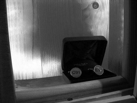
|
A presentation box containing a pair of “CTRL” and ESC” cuff links! |
|
There, wasn’xsxsxst that worth all the waiting? |

Summary
This was a great project for me, I learned a lot from doing it and had frustration and fun in pretty much equal measure.
Who knew there would turn out to be so many different ways to do it! I guess the beauty of it is that there is not a single “right” way to do it; if it works, it works—whatever method you use. It’s an unusual project for an electronics book because it has as many dependencies on where you install it as on what components and parts you use.
This project was one that I have always had in the back of my mind to do. Finally, this book gave me an excuse to do it, and it did not disappoint!
However, I’m afraid I still don’t know what to keep in my secret compartment.
Coming up Next
Here Kitty, Kitty: Random laser beams to drive your pets crazy.