
![]()
Moving to Mesmerize
In this chapter we’ll look at three small projects and some associated ideas and techniques. Each project involves actual or virtual movement. Each of these projects is—while simple in itself—intended to provide some interest and provoke other ideas, or just provide a little simple fun for you or whoever you feel like sharing it with.
Duck Shooter is a classic game that you’ve probably played at the fairground or arcade. In those real-world versions of the game, hinged cartoon duck targets go around on a chain and you have to use the provided air guns to try to hit them as they move across your line of sight. If you get all the ducks down before your time is up, you get a prize (usually quite a perfunctory one).
There have been duck shooter arcade games, pinball games, and alley games since the late 1930s. Ever since computer games were new, versions of this game have been available. For example, Sega had a version of it in 1975, various versions of the game have appeared over the years which use TTL or CMOS logic chips, and of course in more recent years there have been numerous MCU implementations and numerous Java game implementations of the same basic game. Well, you’ll be glad to hear that although the format of this game follows the duck shoot format, there isn’t a duck in sight. They’re LEDs really, but we’ll call them ducks. Okay then!
Following is a summary of the rules:
- You have an 11-slot “duck run”; each slot is represented by an LED.
- You have a button to press that represents your gun. Your gun is locked into position and can only shoot at the middle slot of the duck run, represented by LED number 6.
- At the start of each level in the game, a single duck (represented by a lit LED) progresses across the duck run from left to right. When it reaches the end, it reappears at the left and starts again.
- You must time your shot so that you hit the duck when it reaches the center slot. If you do it right, you hit the duck and its light fades out. If you miss, the duck is cloned! So now there are two ducks parading around in front of you. Miss again and there’ll be three ducks—and so on. When you fire your gun, the duck run stops for a moment, so you can see what’s happening.
- When you have managed to kill off all the ducks, the level ends and you move on to the next one. Each level is the same, except the duck’s progress gets faster and faster and that means that you have to be more and more precise.
- If you manage to play through all the levels your reward is . . . a little light show on the duck run. It’s a perfunctory prize, just like at the fairground. How true to life is that?
In hardware terms, this is quite a simple game. Eleven LEDs are connected from the +5-volt supply, via 11 270 ohm resistors to 11 AVR pins. A push button is connected to a twelfth AVR pin. And that’s it really!
![]() Note We’ll also build in a secret Easter egg feature; when the player presses the gun button for more than ten seconds, the game will show a preview of the winner’s light show.
Note We’ll also build in a secret Easter egg feature; when the player presses the gun button for more than ten seconds, the game will show a preview of the winner’s light show.
The Duck Shooter Circuit
Figure 5-1 shows the circuit diagram. In the diagram, I have instanced a push button with a built-in LED (S2-LED), but you don’t have to use such a push button. I just used a little PCB-mounted push button on my prototype (as we shall see later). An illuminated push button is just for show really, but it would look nice!
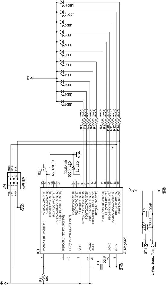
Figure 5-1. Duck Shooter game circuit diagram
I’m going to use this project to show how to transfer a design from a breadboard to something more permanent. It’s not an overly complex design, but it is complex enough to show you how to make the transfer from breadboard to solder board.
Making Duck Shooter into a Keeper
All electronics enthusiasts have their own favorite way of producing a “keeper” project (i.e., one they want to keep, not just a breadboard version that they subsequently break up). Some favor making a printed circuit board (or using services allied to open source packages like Fritzing or Eagle to get a PCB produced for them); some favor a strip board on which they solder their components and cut away sections of copper strip to isolate them from one another; some people like using protoboards, where they solder their components into individual holes and then solder on wires from point to point; some people use various kinds of wire-wrap schemes. For a selection of different solder boards see the following link:
www.verotl.com/prototyping-products
My own favorite for simpler keeper projects is tri-pad solder strip board. This simplifies the tedious business of cutting off copper connections between components because, on a tripad board there are only ever three holes connected to any one connection point—thus the name. For an example product, see
- www.maplin.co.uk (UK) (stock number JP52G).
I haven’t found a U.S. source of this product, though I’m sure there must be one, but you could use various protoboards.
- www.mouser.com (stock number 574-45P80-1).
- www.sparkfun.com (stock number PRT-08619).
Figure 5-2 shows a close-up of a tripad board.
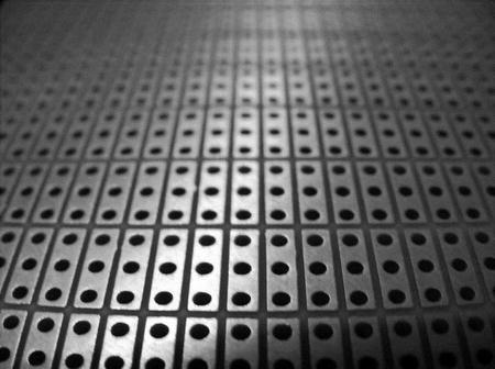
Figure 5-2. Close-up of a tripad board
As you can see, the solder pads are arranged in groups of three pads (thus the name), so you just need to choose your component positions such that they bridge across tripad islands and then you can make other connections from there. There is no tedious track cutting required—as when you use continuous solder strip boards—but you can still get a useful number of components on quite a small board space. The holes are 0.1" (2.54 mm) apart and for the Duck Shooter game we need a board that is 33 holes by 38 holes (give or take one or two either way). This makes the board dimensions about 3.5" ´ 3.75" (850 mm ´ 952 mm).
Building Duck Shooter
Figure 5-3 shows a piece of tripad board cut to size and with some mounting holes drilled through it, one near each corner. Drill carefully and slowly and hold the board steady; it’s very easy to break off a corner if the drill catches because you go too fast. Been there, done that!
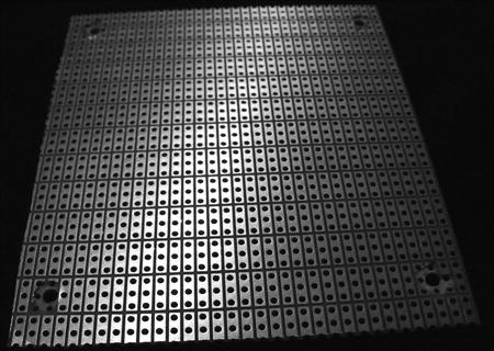
Figure 5-3. Tripad board cut to size for Duck Shooter game
I’m a fan of IC (integrated circuit) sockets; some people don’t like them, but I’ve found that they save a lot of hassle if in the future you need to change a chip out. Yes, after some period of time (usually years) they can cause connection problems due to contact oxidization; however, such problems are easily fixed by reseating the chip in its socket. Also, using sockets means that you don’t have to expose your chips to soldering heat, since you solder the socket into place and plug the chip in later on. So, I almost always use sockets—as you can see from the picture of the completed topside of the Duck Shooter board in Figure 5-4.
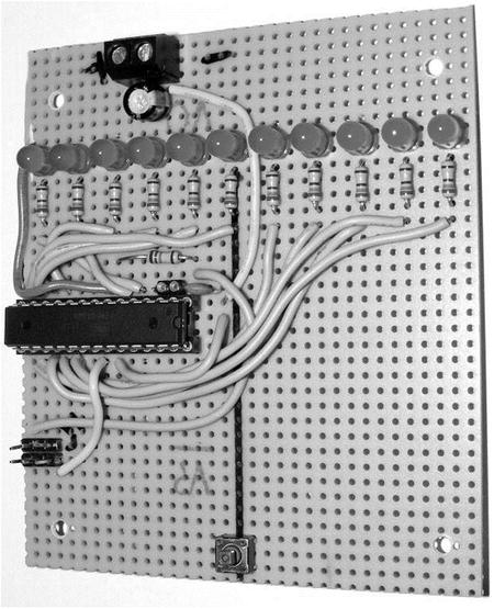
Figure 5-4. Duck Shooter project board topside
As the photo shows, the LEDs are arranged across the board at three-hole intervals. The button is at the opposite end of the board. The MCU is in the middle, and ISP jack is close to it. The power connector is at the top of the board above the LEDS. Before installing any wiring jumpers or resistors on the board, I used a Sharpie pen to make a bold line from the button to the target center LED, indicating the line of fire.
It’s not strictly required (and it’s not on the circuit diagram) but since I had an old IC socket, I cut a couple of pin sections from it to install a socket arrangement for pins 2 and 3 (serial RX and TX, respectively) in case I needed them. The software for this game does output some game metrics to the serial port, which might be of interest to someone . . . sometime! Figure 5-5 shows the serial port and the ISP plug for programming the MCU in situ.
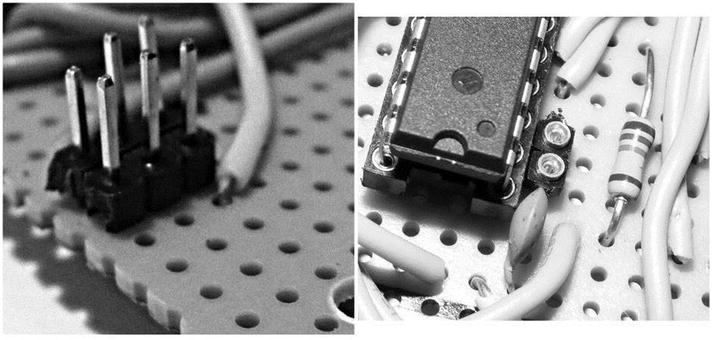
Figure 5-5. ISP -plug and serial port add-on wire socket
Most of the wires for the ISP plug (and a few other wires) are actually routed under the board as you can perhaps tell from the photo in Figure 5-6. For details about the ISP connector, refer to the “About In-System Programming” section of Chapter 2 of Practical AVR Microcontrollers (Apress, 2012), specifically Figure 2-9.
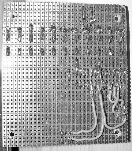
Figure 5-6. Duck Shooter board underside
You may just be able to see in Figure 5-6 the line of stiff wire that goes from left to right along the + side of all the LEDs. This carries the +5V feed to the LEDs.
If you’ve never made a board like this before it can seem quite a daunting task. However, the reality is that as long as you have the right tools for the job and some patience, it’s not hard. It’s just a question of methodically working through it and not rushing it. Your fine-tip soldering iron, your helping-hands gripper, and your magnifying glass should all help make it easier and even enjoyable. Use the solid wire—similar to the breadboard jumper wire—which, by now, you should be used to using. Avoid using stranded wire, which tends to “feather” at the ends and make hard-to-spot short circuits between components.
Following are some tips and points to watch out for:
- If you are unfamiliar with soldering, find one of the many tutorials on the Internet before you begin. The golden rule (as you will see in any of those tutorials) is “heat the job, not the solder.” In other words, if you’re soldering the pin of an LED, heat up the pin and then apply the solder to the pin: don’t heat the solder and let the melted solder fall onto the pin! The latter method will make what is known as a “dry joint” which—in a digital circuit—may initially work but will soon fail. Heat the job, not the solder. Did I say that before? Good! It’s very important.
- Be safety aware: if you have some safety glasses that give you good visibility, use them. Never, ever, flick solder around. Hot solder burns, and burns and burns. It burns holes in carpets, furniture, and, given half a chance, you. Don’t give it any chance. Use a soldering iron with a proper holder or holster.
- Inhale as little solder smoke as possible. If you have a desk fan around, run it on low to waft the smoke away from you toward an open window if at all possible. If the room has an extractor fan, use it. Don’t solder in a confined space. In any case, find a way to avoid breathing in any significant amount of solder smoke.
- Be methodical. Work from the circuit diagram (or a photo copy of it) and as you install each component or wire, cross it off on the diagram. Use a pencil so that you can erase any mistakes you make.
- Don’t solder one point for too long. Even things like resistors and capacitors can be damaged if exposed to the heat of a soldering iron for too long. ICs, transistors, LEDs, and other semiconductor devices are very easily heat damaged, so don’t hold the soldering iron tip on their leads for more than two or three seconds.
- Where two adjacent pins need to be connected, don’t bother putting a wire between them, heat both pins and flood that little area with solder until they are joined together by a solder blob.
- Keep the soldering iron tip reasonably clean. Use a piece of kitchen paper towel which has been dampened with a little water to wipe the tip with if it gets messy. After cleaning, melt a little solder onto the tip to keep it coated. Many soldering stations (usually consisting of the iron itself and a holder or holster) will come with a cloth or special sponge that you can moisten with a little water. You then use this dampened surface for cleaning the soldering tip.
- When you have finished (or think you have—there’s always one more thing to do!) go around the board with a watchmakers’ fine-blade screwdriver or perhaps a craft knife and carefully run it between adjacent pins that are not meant to be connected to make sure there are no minute solder bridges shorting them together.
- When you connect your power source, make sure you have a fuse in the + lead. See the “A +5-Volt Regulated Supply” section in Chapter 2 of Practical AVR Microcontrollers (Apress, 2012) for information on how to do this if you are in any doubt. The Duck Shooter game uses no more than 1 amp, so a fuse at that value should be sensitive enough. If you’re using a bench supply that has a current limiter, make sure the current limiter is set on low for the first power-up of any new board.
If you are truly daunted by the prospect of building this as your first soldering project, try an easier “get started” project to cut your teeth on. A good project for this might be one of the 555 timer chip circuits shown in Chapter 3 of Practical AVR Microcontrollers (Apress, 2012). That might give you the confidence to progress to this one. Like most things, it does get easier, the more you do it!
As the circuit diagram shows, the Duck Shooter game is intended to run from a +5V supply. However, you could also run it from 3 x AA batteries (giving about 4.5V) if you wanted to. The LEDs won’t be quite as bright, but the difference is very small.
Going Further
Many developments of the basic game presented here are possible. You may want to build your version into a project box of some kind, or even build it into something else. A friend suggested it might be fun to build it into the arm of a chair in a TV room. I guess it would give you something to do during those interminable commercial breaks! If you wanted to box the project, you would need to raise up the LEDs above the rest of the circuit, either by leaving their legs longer than I have done on my prototype or perhaps by using bits of socket strips (like the one I added on for the serial port) to raise up the level of the LEDs. For a compact version of the game you could use bar graph LEDs such as
- www.sparkfun.com (sku: com-09935) (United States).
- www.maplin.co.uk (stock number BT65V) (UK).
The problem is, those only come in ten-LED groups (you can also get eight-way groups if you shop around), and so you’d have to rearrange the game somehow.
If you wanted to go nuts on the game you could dispense with the idea of driving the LEDs from the AVR directly. You could use a smaller AVR and one or more TLC5940 chips (see Chapter 4) to drive a much larger number of LEDs which you could arrange in various shapes (circles, circuits, etc.).
The Duck Shooter game software is quite big and so is not reproduced in full in the book itself, but you can download it via the book’s web site (www.apress.com/9781430244462). The following is a code walk, function by function:
And that’s it for the Duck Shooter game. I hope you enjoy building and playing it.
The second of our simple projects in this chapter is somewhat grandiosely called an animation projector—but it’s really just a simple MCU controller version of a shadow puppet. The idea is that a single strong light source in a darkened room can, when interrupted by a shape, cause that shape to appear enlarged on a screen or an opposite wall. If the shape moves across the light source, then you get the illusion of a large moving object on the wall opposite the apparatus. We’ve all played with this idea at some time or another.
In this project we set up a single bright light source (a high-intensity LED light) and we build a simple motorized movement mechanism using a servo motor and a few household bits and pieces to move a shape around in front of the light. In a darkened or low-lighted room it’s very effective. We give the MCU the ability to control the light source and to move the shape and we can even allow the MCU to be commanded via the serial port, which would make it easier for this little project to form part of something larger, such as a coordinated display or an art installation using many such mechanisms, synchronized by a central controller.
Building the Shadow Puppets
To build this quickie project I used some bits of scrap wood, a few self-tapping screws, a strip of 1/4" (about 6 mm) plastic that I cut out of an old storage box that was out for recycling, some stiff wire, a rubber band, and a couple of hooks with self-tapping screws. I used a servo motor and 3W high-intensity LED. I only intended this as a proof of concept, not a “keeper” project.
First the servo motor is mounted on a frame made of scrap bits of wood, as you can see in Figure 5-7. Then, I drilled a pilot hole in one end of the frame and screwed one of the hooks into it. These don’t have to be hooks; they could be long wood screws. Next, I drilled a hole in each end of the plastic strip and fixed the rubber band through one end: the other end of the rubber band goes around the hook.
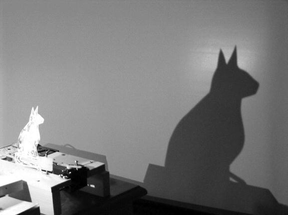
Figure 5-7. MCU shadow puppet
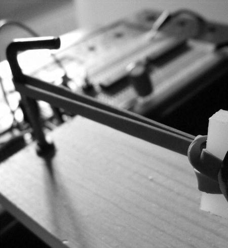
Figure 5-8. Rubber band and end anchor hook
At the other end of the plastic strip, I used a piece of stiff solderable wire to link the plastic strip to the motor horn, which has a self-tapping screw (supplied with the motor accessories kit). I soldered the wire ends together to keep them from coming undone.
As it is pulled back and forth, the plastic strip (to which we will fix a silhouette) wants to twist axially. To stop this, I fitted a second hook into the frame to hold the plastic strip roughly vertical (see Figure 5-9). The photo in Figure 5-10 shows the whole thing.
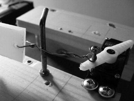
Figure 5-9. Motor end linkage
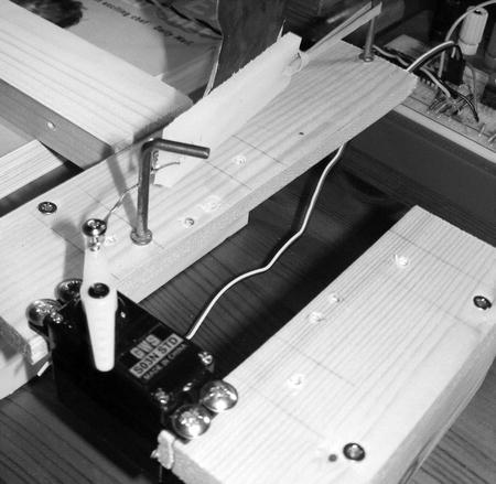
Figure 5-10. Shadow puppet assembly complete
Finally I used transparent tape to stick a silhouette to the plastic strip: since I can’t draw to save my life, my wife kindly drew two sample silhouettes for me on 120 GSM paper. I had planned to mount these on cardboard once I had cut them out, but that proved unnecessary, the thick paper worked fine. In case you too are artistically challenged, I include these silhouettes (see Figure 5-11).
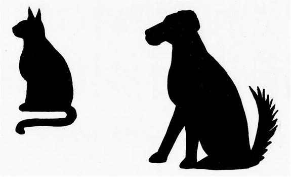
Figure 5-11. Sample silhouettes by Wendy Trevennor
The LED needs to be separate from the main frame so that its distance and height relative to the moving silhouette can be varied according to situation. So, I used some flat-head screws to fix it onto a couple of pieces of scrap stick wood that I made up into an L shape¨ as shown in Figure 5-12.
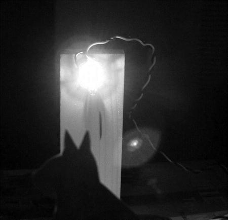
Figure 5-12. LED shining on the silhouette
When the whole thing is put together, with the room darkened and the software running (see Figure 5-13), the effect is really excellent.
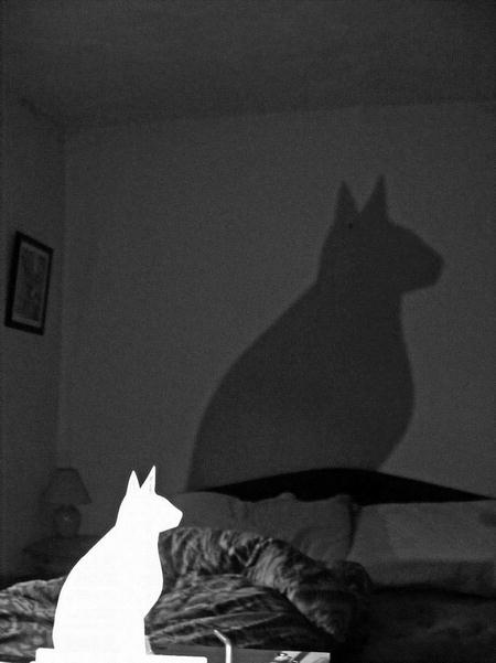
Figure 5-13. Big cat, little cat: the project running
As you can see from the final picture in Figure 5-13, the silhouette size obtainable in a semidarkened room is quite impressive—it certainly impressed our real cat, which ran out of the room in a hurry. Of course, this is just a 3W LED; if you used a higher-power LED you could get an even better effect. I was so impressed by the results of this quickie project that I plan to build a more permanent version. I will use a 5- or 7-watt LED for the permanent version. The mechanism will use a reversible winding motor to get longer travel, and I will use a proper metal spring return instead of the rubber band.
The Shadow Puppet Circuit
The circuit diagram for this project is very simple (Figure 5-14). If you plan to build your own version of this as a keeper project, you’ll need to build as per the circuit diagram.
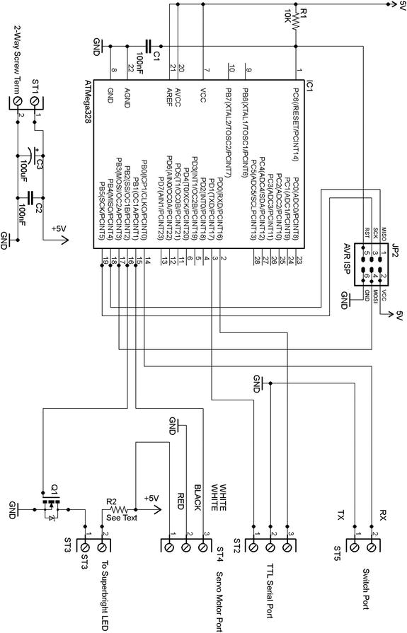
Figure 5-14. Shadow puppets circuit diagram
Referring to the circuit diagram you can see that this project only requires +5V, at about 1 amp—depending on which LED and motor you use. Because this project involves a motor (which can pull big startup currents for a brief instant) you will need to make sure the power supply rails have a good reservoir capacitor. You’ll need at least a 100 uF capacitor across your +5V rail, 200 uF would be better! Without this, the motor might spike the power rail sufficiently enough to cause the MCU to crash or hang up. 100 uF proved sufficient for the motor I used, but if you, using a different motor, experience problems, try a larger value smoothing capacitor (or multiple 100 uF capacitors).
In this project, only three items are hung off the MCU: the switch, the servo motor, and the high-intensity LED.
The switch port (screw terminal 5, ST5) allows the connection of a push button to step the software through its different modes (see the “Shadow Puppets Software” section below). The ISP connector is the same as in the Duck Shooter project described earlier in this chapter.
The motor (attached via ST4) is a servo motor, as covered in Chapter 3 of Practical AVR Microcontrollers (Apress, 2012) and other places. This takes a direct logic connection from Arduino digital pin 9 (AVR pin 15). The servo motor is directly connected to the +5V supply lines and its control lead is connected to Arduino digital pin 9. We drive this in PWM mode in the software for this project.
There is a driver transistor for the high-power LED, and this hangs off Arduino digital pin 10 (AVR pin 16). Since the 3W LED that I used requires far more current than the AVR can directly supply to it, we have to use a driver transistor. I used a VNP10N6 MOSFET, which is a logic-level compatible MOSFET that includes a snubber diode. This device can sink up to 10 amps of current, so sinking 330 ma for our 3W high-intensity LED (or even a much more powerful one, should you choose to go down that route) is well within its capabilities. You could just as easily use some other logic-compatible MOSFET (e.g., an IRL540) in its place.
The MOSFET used here does not need a heatsink; it barely gets warm to the touch even after the LED has been on for half an hour. However, if you’re using different components, remember to check for heat issues. The VNP10N6 MOSFET comes in a TO220 package, and the pinout (see diagram below) is a pretty standard one.
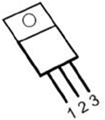
However, don’t assume that all MOSFETs are connected like this, because although most of them are, there will be exceptions and if you make the wrong connections, you can all too easily damage your MOSFET and probably other components too. Always check the data sheet for your device to make sure you have the pinout right. For the VNP10N6 (and the IRL540), if you lay the component on its steel back, the three leads from it are as follows, from left to right:
- Terminal 1 is the input (gate).
- Terminal 2 is the drain (connect to the load): the metal tab is also connected to this terminal to aid in heatsinking.
- Terminal 3 is the source (connected to ground in this application).
The MOSFET connects to the screw terminals for the LED.
The serial port, although not used in the software as it stands, is extended out to ST2 so that it could be used with a TTL level serial port to receive commands if you wanted to extend the project for use in some larger scheme—as previously discussed.
The ISP connector is the same as in the Duck Shooter project described earlier in this chapter.
The listing for the software for the shadow puppet project is quite short and reproduced in full here. There is nothing very complex about this software and I have commented it quite freely. The only thing that bears a little explanation is the program mode variable thisMode. Although it’s an integer, in fact, we only care about the lowest weight two bits. Bit zero, if set, tells the program to power on the LED. Bit one, if set, tells the program to advance the motor position once each time through the main loop and to reset it when it has done a full sweep of the desired range. The following truth table summarizes the arrangement.
|
Bit 1 |
Bit 0 |
State selected |
|---|---|---|
|
0 |
0 |
Motor and LED off |
|
0 |
1 |
LED on. Motor off |
|
1 |
0 |
LED off, motor on. |
|
1 |
1 |
Both on. |
/*

A sketch to control the simple shadow puppet rig
detailed in chapter 16 of "Practical AVR Microcontrollers".
The program runs in one of four modes:

00 = LED off, Motor Off
01 = LED on, Motor Off
02 = LED off, Motor On
03 = LED On, Motor On

When enabled, the motor sweeps back and forth to draw the
puppet across the light shone by the LED. This casts a moving
shadow on whatever surface the light hits (opposite wall etc).
*/

#define SWITCH_PIN 8
#define MOTOR_PIN 9
#define LED_PIN 10

#include <Servo.h>

Servo myMotor;   // The servo motor
int theAngle=0;  // Remembered angle of the motor.
int thisMode =0; // Program's current mode.

void setup()
{
  myMotor.attach(MOTOR_PIN);     // Setup the motor control pin
  pinMode(LED_PIN,OUTPUT);       // Make the LED control pin an o/p
  pinMode(SWITCH_PIN,INPUT);     // Make the switch pin an input.
  digitalWrite(SWITCH_PIN,HIGH); // Enable the pull up.

  digitalWrite(LED_PIN,LOW);     // Ensure the LED starts Off
  myMotor.write(0);              // Ensure the motor starts at home pos.

  Serial.begin(9600);            // Init serial - minimal use.
}

void loop()
{
  // Is the switch pressed?
  if (digitalRead(SWITCH_PIN) == LOW)
  {
  do
    {
      delay(5); // Wait for switch to be released
    }
    while (digitalRead(SWITCH_PIN) == LOW);
    // Switch was released.
    delay (5); // debounce delay
    thisMode++; // Increment the program mode
    if (thisMode >= 4) // If it maxes out, reset to zero
    {
      thisMode =0;
    }
    Serial.print("Software Mode Now = "); // Say the mode
    Serial.println(thisMode,DEC);
  }

// If bit zero of thisMode is set, then the LED is on.
  if (thisMode & 1)
  {
    digitalWrite(LED_PIN,HIGH);
  }
  else
  {
    digitalWrite(LED_PIN,LOW);
  }

// If bit one of thisMode is set, then advance the motor angle.
  if (thisMode & 2)
  {
    theAngle+=3;
    if (theAngle >=150) // Are we at end of desired travel for mtr?
    {
      theAngle = 0;     // We are: reset the motor back to home pos
    }
    myMotor.write(theAngle);
  }

  delay(75);
  if (theAngle==0) // If we just reset the motor, give it time to get home.
  {
    delay(1500);
  }

}
As previously alluded to, you could easily extend this program to receive input via the serial channel to take commands or set the mode. Look at the software for the “WordDune” project (see Chapter 3) for an example of serial channel functions of this type.
Before the era of animated graphics and CGI, the moiré wheel was a beloved staple of sci-fi films and TV show set designers. This wheel creates a pretty simple but very striking effect. You print a fine mesh pattern on two transparent surfaces. You shine a bright light behind them, hold one still and slowly move the other one back and forth across the moiré pattern point. The intersection points of the lines form a morphing grid pattern. When the eye views this pattern, it resolves the result into forming and deforming shapes which come and go with a pleasing fluidity.
If you want a taste of this effect you can get it quite easily. It’s only enough to give you the right idea—not as good as the finished effect, but it gives you a preview without much effort!
You’ll need some thin (60 gsm or less) printer paper. Use a graphics package or the “draw” facility of your word processor to make a page containing a couple of oblong boxes on a single page. Specify no outline and set the fill pattern to be a hatched, as Figure 5-15 shows:
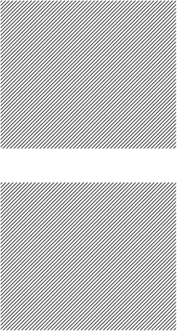
Figure 5-15. An example hatched pattern that could be used on your Moire wheel
As long as both boxes have the same lined pattern, it doesn’t matter whether the lines are diagonal (as in my example), vertical, or horizontal.
Print the page containing the boxes, using the best print quality available to you. If your printer is not reproducing the lines very well, try using a fill pattern where the lines are a bit bolder and not as close together. You can still get the same effect with less dense patterns; it’s just less intense.
Now, cut the page in half with scissors. Find a bright light (e.g., the LED we used in the last project, or just a regular 100W house lightbulb should do). Hold the page halves one on top of the other, right in front of the light. Hold one of the pages steady while you slowly rotate the other one. As long as enough light is getting through the paper (you’ll need thinner paper or brighter light if not) you should at some point see the waves formed by the changing intersections. This gives you a rough idea of what the real thing will look like! So much for the art side of the project! Now, how do we make it?
You’ll need the following things:
- A couple of transparent discs, made of fairly rigid plastic. I’d suggest using discs of between 3" and 5" (76-127 mm) across, but the size and type of these are up to you. They must be the same size and must be transparent (or almost transparent) plastic. A few possible sources:
- Raid the recycling. Quite a lot of consumer goods and foods are packed in semirigid transparent plastic boxes or trays. You may find something you can cut discs from in that line.
- Your local artist’s shop will sell various thicknesses of clear plastic. Go for a thickness that’s not floppy, but which is still transparent and easily cut to shape with normal household scissors.
- DVD or CD recordable “cake box” packs. Most of these come with a “guard disc” at top or bottom (sometimes both) of the disc stack. These are DVD-sized discs, but they are uncoated and therefore almost transparent. You may already have some of these around, but if not, think of someone you know who burns a lot of discs (perhaps at work) and see if he or she would save some guard discs for you. They almost certainly throw them out in large numbers anyway.
- Your local Home Depot, DIY store, or garden center may have some clear plastic sheet that you could use. These kinds of materials are often used for greenhouses, or secondary glazing for outhouse windows.
![]() Note Don’t forget, your disc will need to have a center hole. If it doesn’t already have one, you’ll need to make a center hole of at least 1/4" (about 6 mm) to allow the center spindle through.
Note Don’t forget, your disc will need to have a center hole. If it doesn’t already have one, you’ll need to make a center hole of at least 1/4" (about 6 mm) to allow the center spindle through.
- Some spray-on acrylic varnish. This goes by various names and is used to seal a surface, much like a brush applies varnish. Own-brand products tend to be a cheaper than branded ones and work just as well. You need a spray can; brush-on products won’t work in this application. I used a product called triple thick by Krylon.
- Some inkjet (or laser) decal waterslide paper. This is sold under various names and brands. Most office supply outlets will have it, and you can buy it online from Amazon and eBay among many others. Just search for “waterslide decal inkjet” and you’ll find lots of vendors. We’ll look at how to use this stuff in just a while.
- A +5V servo motor—just like the one we used earlier for the shadow puppets.
- A long thin bolt that can screw into the center hole on the motor shaft. It needs to be a couple of inches long ideally. This bolt is needed to couple the drive shaft of the motor to the uppermost of your plastic discs. You will also need some way to secure your plastic disc to the center bolt. In my prototype I used two of the supplied horns that came with the servo motor. Using a nut, I was able to secure the disc to the center bolt (see Figure 5-19).
Figure 5-16 shows the general arrangement.
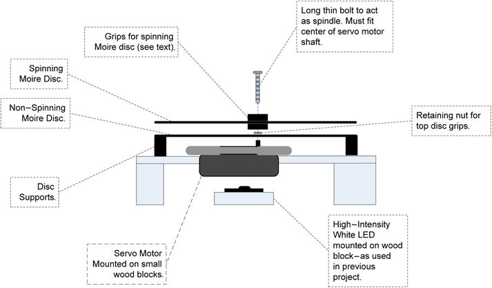
Figure 5-16. Moiré wheel rig
If you have already used waterslide decals in the past and you’re comfortable with using then, please feel free to skip this section. Waterslide paper lets you print transparent designs (photos, logos, moiré patterns, or whatever you want) onto a film that you can detach from its backing and affix to any plastic, metal, or glass surface. You can use it for decorating surfaces such as windows, plastic lunchboxes, or whatever else you might want.
My favorite use for waterslide paper is making light boxes. If you put a waterslide photo on a piece of thin white Plexiglas or Lexan and backlight it with a white or colored LED string you can get a lovely effect—a smaller version of the light boxes you see in stores and that light up advertising displays (see photo in Figure 5-17). If you have the skills, you could make a grid of these backlit boxes and have your own backlit photo gallery! You could use an AVR board and ULN2803 chip combination (see waterfall lights project in Chapter 4) to fade these up at down at will.
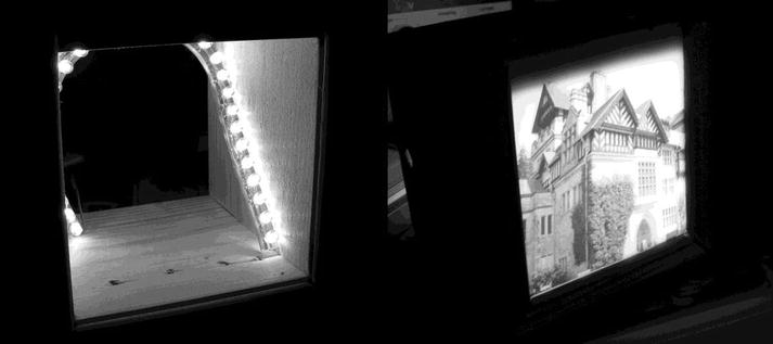
Figure 5-17. Example of using waterslide on a backlit light box
Sadly, I have found that it’s only possible to use waterslide film with comparatively small photos (maximum 5" square is my recommendation) because it can crease and tear at larger sizes. I did once do an 8" ´ 10" but it was far from perfect and took several tries.
Another use I have found is making low-cost 5" touch panels. This method is limited in scope but quite a lot cheaper than using a LCD screen. In my version, the “press buttons” are on a backlit slide (similar to the one in Figure 5-17) and you overlay the image with a cheap four- or five-wire touch screen. Your software then uses touch coordinates to figure out which of the graphical buttons is being tapped. Of course, this approach is only good for applications where one set of permanent buttons is needed. It’s no good for multilevel menu systems. Also, if you want to vary the button layout, you have to remake the backlit image. However, if used in appropriate situations, it makes a vivid and good-looking touch panel, at quite low cost as compared to the LCD approach.
So, how do we use this stuff? Waterslide paper arrives as what looks like standard sheets of photo paper. However, if you look closely you will see that it’s actually a piece of paper with a film bonded to one side of it. The idea is that you print your design onto the film (shiny) side of it, using your normal printer (in color or monochrome). I usually try to do two or three designs at once. The waterslide paper is not cheap and so it makes sense to batch up your usages of it. You’ll also find that you will spoil some of your designs and have to try again, especially at first.
Having printed your designs, you then roughly cut up the paper into pieces, each of which will contain a design you want to transfer.
Next, comes a very important step: spray at least three (preferably four or five) thin coats of acrylic varnish on. This coat seals the printed surface to protect it against moisture (as you know, inkjet print is easily washed away by moisture). Allow each coat to dry (it takes about 20–30 minutes) before applying the next. Make sure you keep count of how many coats you have put on.
![]() Caution Many of these kinds of products give off nasty fumes; be sure to work in a well-ventilated area! Open a window or turn on an extractor fan if there is one.
Caution Many of these kinds of products give off nasty fumes; be sure to work in a well-ventilated area! Open a window or turn on an extractor fan if there is one.
You’ll need a “wet area” such as a sink or drainer to do the next bit. When the last coat of acrylic varnish is dry, prepare a bowl of clean water and get your target surface (in the moiré wheel project, it will be your plastic discs) close to the water bowl ready to have the film applied to them. It can help to dampen the target surface with clean water beforehand.
Place the waterslide paper into the bowl of water (cover it with water). It will immediately try to roll up around itself. Try to prevent it from rolling up, or if it rolls up before you can stop it, gently unroll it back to a flat shape, while it’s still in the water. After you have done this, it should be happy to stay reasonably flat. If the ink is starting to come off the paper at this stage then, you didn’t apply enough coats of acrylic varnish and you’ll probably have to start over! After 30-50 seconds it should become easy to slide the film off the backing paper. Slowly and carefully lift it away from the backing paper. As quickly as you can, transfer the film onto the target surface. If you dampened the target surface you should, at first, be able to slide the film into position (thus the name) but only for a very short time. Apply the film to the target surface as smoothly as you can. Start from the center and using a smooth cloth or a plastic sponge in a wiping motion, gently smooth out any air bubbles that get trapped or creases that may form. It’s pretty easy to tear the film at this stage, so be gentle. Be prepared to mess up and have to start again a few times before you get the knack.
When you have the film applied successfully, leave it to dry for an hour or two. Then, trim off any excess film from the edges of the target surface. Hey, presto! You have a light-transparent surface with your own design on it. Yes, you can use this technique for full sheets of waterslide paper, but don’t expect it to be easy: this technique is most useful when the designs concerned are no more than about half a normal printed page.
Building the Moiré Wheel Project
By now you should have applied your moiré patterns to both discs using the techniques described in the previous section and trimmed off the excess (don’t forget to open up the center hole of the disc). The next step is to secure the top disc to the spindle (see Figure 5-16). I used a 0.1" (M2.5) bolt that was about 1" (25 mm) long. This bolt screws very nicely into the center of the servo motor.
I found that I could use two of the horns (one on top of the disc and one underneath it) that came with the servo motor along with a retaining nut underneath, to grip the disc firmly and secure it to the spindle (see Figures 5-18 through 5-20 ). However, you will have to take a view of what suits your needs when you have the materials and parts at hand. Some large metal washers with small center holes would do the job too.
The bottom disc does not move; it simply needs to be held to position at the required height. If, like me, you’re only building a temporary version of this project, you just need to hold it steady at roughly the right height. I found some metal spacers that were approximately the right height. If you can’t find anything suitable you could try using something like blocks of blu-tack. You need to position the fixed (lower) disc so that it is close to, but not touching, the moving (upper) disc. If the discs are too far apart, the moiré effect will be lessened. The fixed disc needs to allow the spindle to rotate freely, but the disc must not touch the spindle, so its center hole should be quite a lot larger than the spindle.
The underlight can be provided either by a LED string or by the high-intensity LED that we used in the shadow puppet project.
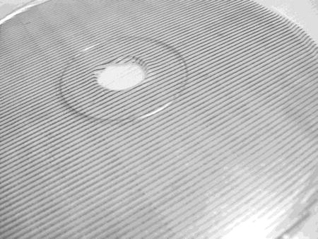
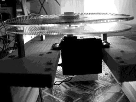
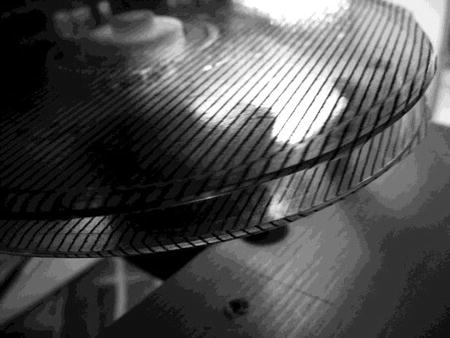
Finally, Figures 5-18 through 5-20 show the prototype rig.
|
This first photo show a close-up of one of the uncoated CD discs I used. This view of the disc is after the waterslide film carrying the mesh pattern has been applied to it but before trimming. |
|
This is a side view of the entire rig. You can see the upper disc is held onto the spindle by the horns borrowed from the servo motor kit. |
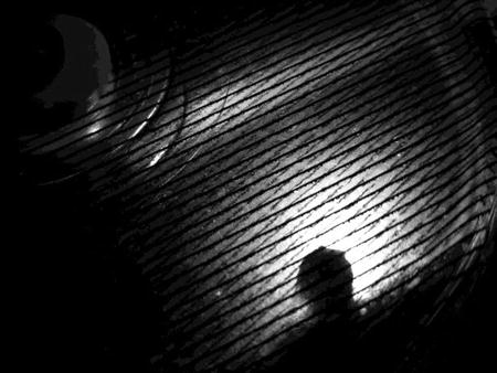
|
A closer view of the two discs with the light shining through them from underneath. |
|
Looking through the two discs with the mesh patterns at the start of the moiré zone. |
The circuit diagram we need for this project is exactly the same as we used for the shadow puppet project in Figure 5-14. The software is different.
Moiré Wheel Software
The software for this project only has to do one thing—slowly and smoothly move the servo motor back and forth in the “moiré zone.” Once you have built up the project you will see that you get the most pleasing effects (the moiré zone) within a comparatively small area of movement. You’ll need to find this zone by experiment since it will depend on what line pattern you used and the relative mounting positions of your discs. You can, if you prefer, just let the servo motor sweep up and down its full arc of travel (the software starts from this assumption) and you will be sure to see a moiré effect at some point during each sweep.
If you do want to tune into the moiré zone, you’ll need to hook up the project’s TTL serial channel to your desktop. As you will recall, the Arduino servo motor library abstracts the angle of the motor for us. So all we have to do is set start and end values in the software. This allows us to quite precisely control the sweep of the turning moiré wheel.
The moiré wheel software reacts to the following commands received at the serial channel:
- S—Increase the motor’s sweep start point.
- s—Decrease the motor’s sweep start point.
- E—Increase the motor’s sweep end point.
- e—Decrease the motor’s sweep end point.
- L—Toggle the state of the LED (on/off).
- M—toggle the state of the motor (stop/start)
- A—show the current state report. Shows sweep start and end points, current angle (useful when you are trying to judge moiré zone boundaries), and LED and motor on/off states.
The adjustment commands enforce bounds checking to make sure the start and end points don’t collide and that the start point doesn’t go below zero or the end point above MAX_ANGLE. If you were building a permanent version of this project, a worthwhile addition to the code would be to write the moiré zone values into EEPROM so that they are not lost at power off and can be remembered for the next session.
Generally I found that fairly short (50 ms) delays between motor steps give the best results. I also tried it with a more general light source, an LED string. It made the moiré effect appear over a slightly larger area but didn’t really enhance it. I found that the moiré zone on my prototype was within a range of about 25 degrees of travel. Obviously that is highly specific and will vary according to the line density you use for your patterns, the spacing of the discs, and so on, but it gives you a guide at least.
The software is quite simple but rather too large to reproduce here. You can download it from the book’s web site (www.apress.com/9781430244462). Following is a summary code walk:
Summary
In this chapter we have looked at three fairly different ways of using AVR controlled movement (actual or simulated). As discussed at the outset of the book, the ways in which you can use a microcontroller to create and control movement are effectively unlimited. None of the ideas or techniques presented in this chapter are in the least bit trailblazing or earth shattering; they are just intended as examples of the kind of things that, when used in combination with other ideas of the same type, can cumulatively add up to something special.
Coming Up Next
The final chapter: Smart Home?