
![]()
Project 4: The Lighting Waterfall
Light the Way—Ever So Prettily!
In this chapter we look at a project that is not only useful but pretty. If you have a passageway or corridor or even a long, thin room in your home that could do with some nice lighting, then this could be the project for you.
People used to expect very little of the lighting in their homes. One nice bright light in the middle of the room, a simple on/off switch, and the job was done. The fact that our parents and grandparents were happy with this kind of lighting was probably a reflection of the fact that their forefathers had to spend their darkness hours trying to read or work by feeble gaslights or even candlelight: so, to them, being able to make a room as bright as daylight whenever they wanted must have seemed like a dream come true. Viva Edison and Swann!
But pretty soon people realized that controlled and varied lighting could greatly enhance and transform even a very plain room: the more chic lighting styles of the 1950s and 1960s were born. Semiconductor technology entered the scene when—in the 1970s—it became possible to make a light dimmer that would fit into the footprint of a standard wall switch. Now, you could not only place lights strategically to enhance a room, you could set their brightness to whatever you wanted. Why not have several lights? Have some with plain white lamps in, and perhaps some different colored ones to create different pools of light within the room.
A steady stream of incremental developments to lighting followed that continues to this day. If you could make a device that would allow people to manually control the brightness of their lights, why couldn’t you give them an IR remote control, so that they could do it from their seat? If you could remotely control the state and brightness of all the lights in a room, why couldn’t you give control of those functions to an automated system? If that system could be given access to “people sensors,” why couldn’t the lights automatically come on when someone entered the room and go off a little while after the last person left it? Do you need different lighting setups in the room for different times of the day, or days of the week? No problem; the control system could be made to remember “scenes”: each scene can have preset color combinations, brightness settings, even light directions if you add a motorized direction setting to the light fittings.
In more recent times, the LED—previously thought of mostly as an indicator light or for making seven-segment displays for clocks or technical equipment—suddenly got brighter and jazzier. Developments such as Professor Shuji Nakamura’s invention of the blue LED in the mid-1990s (he also perfected bright LEDs in green and white colors) made LEDs a serious contender for the filament lamp’s crown as light source of choice. LED lights use a great deal less electricity than conventional lighting methods, and they have a much longer lifetime. However, LED lighting was initially far more expensive than traditional lighting. This is partly because LEDs work on low-voltage DC, not high-voltage mains AC and so the additional cost of providing a converter is involved, but the price difference is also due to higher production costs. Also, LED light gives a different, more directional light than the lights we have been used to, which has met with some consumer resistance. However, with innovations such as “warm” LED lighting, better diffusers, and ever higher intensity devices, plus the ever increasing cost of domestic electricity and desire for more lighting control, the advance of LED lighting has been slow but relentless—to the point where it’s no longer impossible to imagine a time when most homes will be mainly lit by LED lighting.
One characteristic of LED lighting is that it often aggregates lots of small LEDs to form a light source. For example, the LED work light pictured (assembled and disassembled) in Figure 4-1 uses 72 pure white LEDs to provide a bright directional work light1 from a 6V battery source. In the case of this particular light all the LEDs come on at the same time and brightness; this is just a work light. However, in other products, LED lights intended for use as disco light shows or ambient lighting components for restaurants, LEDs are organized into groups or banks of lights to give very fine control over lighting levels and sequencing.
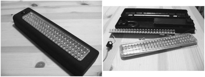
Figure 4-1. 72 LED worklight
When you bring this together with the ability of an MCU to exercise detailed control over a large number of individual LEDs or sets of LEDs, you can suddenly see the possibility of exercising endlessly detailed variable control over room lighting schemes and doing things that, previously, were prohibitively complex or expensive.
The project we’re about to see is but one example . . .
Most homes have some kind of hallway, corridor, or passageway, either inside or as a covered way outside. Some homes have long, thin rooms which can be difficult to light with any style. When we moved into our house, the 16-foot (5 meters) passageway that goes along the middle of it was lit by a single pendant, an unshaded bulb hanging from the ceiling. The switch for this light was at one end of the passageway. It let you see where you were going, but it received zero points for eye appeal, convenience, and style. I wondered what I could do to light this space better: this project (or, more precisely, projects, since we’ll also see the design for a MKII version) was the result.
I’m a great believer in the interior designer’s notion that if you want to give a room some style, you must light it with indirect light sources. Okay, you do still need to have a brash, bright light available for cleaning, decorating, looking for a lost key, and so on, but take a cue from the hospitality industry! Most clubs, restaurants, and bars have fluorescent tubes on the ceiling, but they’re only there so that the cleaners and maintenance staff can see what they’re doing—and those places can look pretty plain and ugly in that mode. There’s a reason we refer to the “cold light of day”! However, when serving their main purpose, being a party place, the plain lights go off and the atmosphere lighting takes over—usually making the place look superb. Why should the relaxation rooms of your home be any different? Cold but bright lights for working in them (found that key yet?) and softer, more varied, lights for when you’re relaxing in them. So, I started with the idea that these would be hidden, indirect lights.
Nobody stays in the passageway, people only pass through on their way to one of the other rooms, and so my next design goal was that the lights should come on when needed but automatically go off again after some fixed amount of time. Then, inspired by the long, thin nature of the space, I seized on the idea of a lighting waterfall; the lights would come on in sequence along the line of the passageway and go off in sequence again when the time-out was reached. Since there were entrances at both ends of the passageway, why couldn’t the waterfall come on in the direction of travel? Could the lights fade in and fade out, rather than clicking on or off one by one? Whoa! Suddenly I had a spec in my head for this project!
I was convinced early on that this was going to be a LED lighting scheme. At this time, RGB (Red Green Blue) LED strips were still pretty expensive, but I was quite taken with some flexible LED lights strips that I bought from an online auction site. Being, I think, intended for used on vehicles, these run on 12V DC and seem to be completely waterproof. They can be flexed into pretty much any shape you might need.
I decided to use these for the project and so I bought some single color strips, like the one shown in Figure 4-2, from a well-known Internet auction site. These are available in different lengths containing 12, 24, 30, or 48 LEDs on a flexible PCB set inside a very flexible plastic gel casing. Alternative sources of supply are
- www.bestlightingbuy.com/motorcycle-led-strip-car-lights-flexible-grill-light.html (United States).
- www.brightlightz.co.uk/categories/led-strip-lights-flexible (UK).
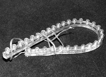
Figure 4-2. Flexible single color LED strip
There is, of course, no reason why you should not use SMD (Surface Mount Device) LED strips—cut to your desired length—in your implementation, in which case you would probably need:
- www.sparkfun.com (search for COM-10259; they do many others too) (United States).
- www.maplin.co.uk (search for stock number N56CF, and others) (UK).
This was so obviously a job for an MCU that I never considered any other implementation approach, but that requirement for the LEDs to fade in and out gave me a problem. The ATmega328 that I wanted to use for this project offers four pins with usable hardware PWM capability. These are
- Pin 5 (Arduino D3).
- Pin 15 (Arduino D9).
- Pin 16 (Arduino D10).
- Pin 17 (Arduino D11).
Pins 11 and 12 (Arduino pins D5 and D6, respectively) also offer PWM; however, as noted on the Arduino web site, the millis() and delay() functions of the Arduino software share the same internal timer used to generate PWM on those pins and so when used at low-duty cycles these pins may not fully turn off. Well, we need a reliable black level for this project and we make extensive use of the delay() function in its software; therefore, it seems sensible to stick to using just the PWM pins that can be guaranteed to behave as expected.
All of the above meant that I could only drive four LED strips from the MCU in the way that the spec called for. After a lot of thought, I decided that I would go ahead and build a four-way setup and see how it looked and revisit the project for a MKII approach if necessary.
The project requirements were
- To provide a set of four LED lighting strips (I eventually settled on warm yellow as the LED color, mainly because the walls of the passageway are painted white and would mix well with it).
- To have each lighting strip’s brightness be independently software controllable and dimmable between nothing and full brightness using PWM.
- To provide a “person detector” at either end of the passageway which, when triggered, will turn on the lights for a preset 40 seconds.
- To have the lights to come on and go off in a waterfall sequence, starting at the end at which a person enters the passageway. At the end of the time-out sequence, lights go off in the same sequence they came on (i.e., first off is the one that was first on).
- To put the lights permanently on at full intensity via a manual button on the control box.
- To turn the lights off permanently, via a button on the control box, so that they cannot be triggered.
I elected to use two Paradox PA-461 PIR sensors as the “people sensor” elements in this project. These can be obtained at quite low cost if you shop around. You can find a lot of details about these sensors in Chapter 4 of Practical AVR Microcontrollers (Apress, 2012), so I won’t recap here. Suffice it to say that you feed the sensors a +12-volt supply and they momentarily break a closed loop contact whenever anyone walks past them. If you can’t get these particular sensors, it doesn’t matter; your local vendor or favorite online source should be able to supply something similar.
For the purposes of this project I refer to the sensors as
- Sensor 1—also called the “near sensor” because it is near the control box
- Sensor 2—also called the “far sensor” because it is not near the control box
The physical layout diagram in Figure 4-7 makes this arrangement clear.
Proving Circuit
In order to develop the software for this project and to refine the hardware design I used the circuit diagram shown in Figure 4-2 to build up the design on the test bed —as built in Chapter 2 of Practical AVR Microcontrollers (Apress, 2012). If you want to try this design out for yourself, follow this circuit diagram.
As you can see, there is nothing special about it; it uses a ULN2803A Darlington transistor array chip to allow the AVR to drive the LED strips. Each of my LED strips (24 LEDs per strip) uses about 220 ma at 12V, which is well within the capabilities of the 2803, but your LED strip consumption may vary, so check with the vendor before you buy. Some longer (48 LED) strips pull quite a lot more current, so you need to make sure you don’t go above about 350 ma per driver or you may get into heat problems with the 2803 and start needing to fit a heatsink.
The circuit diagram shows the MCU as an ATmega328, but originally this used an ATmega168: they are pin-compatible devices, the 168 just has less memory, but that should not matter in this application: if you have an ATmega168 and want to use it, give it a try!
Whichever MCU you use, you should make sure it’s running at 8 MHz. Running the MCU at the “out of the box” speed of 1 MHz is not sufficient in this application; it is too slow. If you’re not sure how to set your AVR to run at 8 MHz, see the discussion on AVRDude and the CKDIV8 fuse in “AVRDude Out of the Box” in Chapter 3 of Practical AVR Microcontrollers (Apress, 2012).
As the circuit diagram in Figure 4-3 shows, the four outputs of the AVR which are capable of hardware PWM are used to drive the inputs of the ULN2803A driver chip and therefore the LED strips. The remaining, unused, driver stages on the 2803 have their bases (5B-8B) grounded.
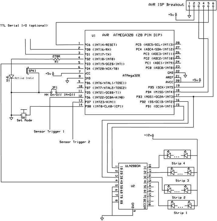
Figure 4-3. Waterfall lights on test bed rig
Mostly this will be used as an automatic system, and so the control box is tucked away somewhere unobtrusive. Therefore, rather than use multiple buttons, I decided to have just one push button and to use it to step through the three (plus one) possible controller modes.
- Automatic mode: Sensors trigger lights to fade up in appropriate order according to which sensor triggers them.
- ON mode: Lights come on and stay on.
- OFF mode: Lights go off and stay off—even if sensor triggers received.
- A “pretties” mode: The LED sets fade up and down in quick alternation. This is the “Easter egg” feature of this program—you get into it by holding down the mode button for about seven seconds until the unit bleeps. Nothing spectacular, but something to surprise your friends or family with, especially once they have gotten used to the normal functions.
The downside of using only one button is that the unit needs to signal to the user which mode is being selected at each button press. For this purpose I added a small piezo speaker. It can be directly attached to an AVR pin and can, if installed properly, be easily loud enough for making the required bleeping noises inside a box. The speaker emits
- A rising tone when a button press sets the unit into Automatic mode.
- A constant pitch tone when entering ON mode.
- A falling tone when entering OFF mode.
I did toy with the idea of having the unit do a short beep whenever the sensors sent in a trigger pulse, but I quickly concluded (based on experience in the past) that such a feature would quickly get to be annoying.
I added a heartbeat LED connected to pin 4 of the MCU (Arduino pin D2). This is just a single LED that is pulsed on and off once per second by the program (and just blips very briefly when the unit is in OFF mode). This is handy as a visual confirmation that the software is still running and on the rails!
I also added a jumper, JP1: This is intended to let the software know whether or not it is being used with an integrated home help “smart home” system. When this jumper is IN (i.e., the two contacts are bridged) then the software will not expect to output status information on its serial channel to a superior system. This is largely a future-oriented feature, not of immediate use.
Whether or not the unit thinks it is participating in a larger “smart home” setup, it will always accept incoming commands from the serial channel. Most of these were originally for helping with test purposes (e.g., to be able to simulate sensor activations when no sensors were actually wired up to the initial version built up on the test rig). However, many of them are useful to keep in the mix for troubleshooting the unit, should any problems occur. I originally envisaged just one or two commands, but by the time I had completed the software, the command set had grown. The following table lists the commands in the finished software,
|
Command |
Effect |
|---|---|
|
ALLOFF |
All LED strips go off and stay off. |
|
ALLON |
All LED strips come on and stay on at full brightness. |
|
BEEP |
Makes the unit beep. Useful to ensure the unit is still operating properly. |
|
CLOCK |
Shows the system time, this is how many milliseconds since the unit started. |
|
CYCLE |
The unit enters FADECYCLE mode for 1.5 times the length of the period set for sensor triggering. |
|
FDN |
Fade Down: all LEDs fade from maximum brightness to off. |
|
FUP |
Fade UP: all LEDs fade up from minimum to maximum brightness. |
|
Ixxx |
Intensity. Sets all LED strips to the indicated intensity level, where xxx is a number from 0 to 255. Illegal values are ignored. |
|
SPP |
Show PWM Parameters. Prints a table of the current PWM settings for each LED strip |
|
Txx |
Trigger: Simulates a trigger from an external sensor. xx should 01 or 02 according to the sensor to be simulated. |
The final software for the MKI waterfall lights (then still called the “passageway lights”) was version 2.0a. The software is rather too big to reproduce in full here, but it is downloadable from the book’s web site (www.apress.com/9781430244462). The following is a function-by-function code walk summary of the software:
|
Function Name |
Args/return type |
Commentary | |||
|---|---|---|---|---|---|
|
Global header |
None/void |
In the global header section of this program a set of hardware related constants are declared. For example, these set pin numbers for items like the BUTTON and the SOUNDER. Then the constants for the three different available fade rates are set. The SEQUENCE_STAGGER constant is declared to be 500 milliseconds: this determines the speed of the waterfall effect (i.e., the time delay between each LED strip down the line being taken to its next level of brightness during a fade up or fade down). Then the sensor count is declared. You could just run this with one sensor if you wanted to. Constants are declared for the various light modes that the LED strips can enter. Only FADEIN, FADEOUT, FADECYCLE, and ON and OFF are actually implemented in this version. After explaining PWM, the main data structure used by the program—a LIGHT_STRUCT—is defined and an instance of it (the lights[] array) is created and filled with details such as pin numbers that control each light represented in the array. All PWM values are set to zero, meaning all lights start as off. Next, constants are declared to define things like how many lights are being controlled and how long they stay on when triggered. After defining the program modes and the push-button long press duration (for the Easter egg) and doing a few more initializations and declarations, the header is done. | |||
|
setup() |
None/void |
In the setup() function the various pins required for the control button, the LED strip drivers, the heartbeat LED, the sense pin, etc., are all set to the appropriate pin type, INPUT or OUTPUT. All input pins have their pull-up resistors enabled by writing a HIGH to them. The smart home help jumper is read to see if that mode is needed. The serial channel is initialized and an announcement sent to it with the program version number and build date. Finally, the power up sound is made on the internal speaker. |
|||
|
loop() |
None |
The program now enters the main loop. For various reasons, we don’t want the loop() function to continually reinitialize at each loop in the usual way. So all the code in the loop() function is run inside a do-while loop that can never end. It will run round until forever, but without reinitializing any of loop()’s resources as it otherwise would. We could use static variables but. . . nah! The loop starts by calling the doSerialInput() function (see below in this table) Then, it looks to see if the mode button is pressed. If the button is NOT pressed now, but it was pressed last time we checked, then we check if it was a long press (Easter egg) or a normal press. If it was a normal length press, we call the shortPress() function, or the longPress() function if not. If the button IS pressed now, we check to see how long it’s been pressed for and action a longPress() if that is called for. If the button is pressed now, but was not pressed last time we looked, then we remember the time now: this, when the button is released in future, allows us to know how long it was pressed for. Next the program checks the sensor inputs. If the program is in normal (automatic) mode and a sensor is found to have been triggered then the sensorEvent() function is called. The sensors used in the prototype stay active for about one second, easily long enough for the main loop to spot their activation. Different sensors with shorter activation durations might need some adjustment to this approach. |
|||
|
Now, the program enters the lights processing loop. Inside this, the required state of the lights—as represented by the contents of the lights[] array—are made real by writing out each light’s PWM state to the pin that controls it. Individual lights can be set to enter different modes in future, principally in the fadeCycle() function (see below in this table). We next check to see if any such change is pending for the current light and action it if so. Turn-off times for lights are processed, and the lights processing loop ends. If the 100th-of-a-second function is due to be run it is invoked now. The hundredthSec() function does fade advances and other things — see below in this table. |
|||||
|
oneSec() |
None/void |
The oneSec() function is called once per second from hundredthSec(); it pulses the heartbeat (a.k.a. “active”) LED at a rate appropriate to the current mode of operation (once per second for normal, very short bursts of light for OFF. |
|||
|
hundredthSec() |
None/void |
hundredthSec() is a function that is called once every 100th of a second from loop(). It acts as a dispatcher for once per second events and for lights processing events (such as fade progressions and control changes). The various lighting modes (FADEIN, etc.) are implemented in a switch table within this function. Important to realize that this function only works on the lights[] array, it does not directly change the pin states—that only happens in the main loop() as we saw above. |
|||
|
doInputBufferParser() |
None/Boolean |
doInputBufferParser() is called from doSerialInput() when that function recognizes it has received a terminator character. This function uses a switch table to try to recognize one of the implemented command and checks the supplied command line arguments (if any are needed) before it calls the required command’s implementation function. Unknown commands get the “unknown command” response, and commands that fail to return a success value, or command line arguments that are incorrect in some way all result in a “Cannot execute command” message. The function returns TRUE if the command succeeded or FALSE if not. |
|||
|
showPwmParameters() |
None/void |
This function simply prints a short report out to the serial channel showing contents of the lights[] array. |
|||
|
sensorEvent() |
Int sensorNum /Boolean |
The sensorEvent() function carries out the light sequencing when a sensor trigger is received. Triggers only have effect if the lights are currently OFF. If the lights are already active, nothing is changed and the function returns FALSE. The currentState of lights[0] is sampled to determine whether the lights are OFF at the time of the trigger. The lights are programmed to fade up in a time-staggered sequence starting from now. If the sensorNum is 1 then the lights fade in the array order 0,1,2,3 If the sensor number is 2, then they switch on in descending order. When a trigger has been accepted and actioned the function returns TRUE. |
|||
|
doBeep() |
None/void |
The sounder makes a steady one KHz tone for half a second. |
|||
|
setFadeCycleMode() |
None/Boolean |
If the current mode is not INACTIVE (i.e., OFF) then this function puts the lights into FadeCycle mode for one minute. If the unit is currently in INACTIVE mode, then the function returns FALSE. The function acts upon the lights[] array, not the hardware directly and returns TRUE when the mode has been set. This function is called from the longPress() function. |
|||
|
longPress() |
Unsigned long pressDuration /void |
This function is called from loop() when a long button press is deemed to have occurred. In fact in this version it simply calls setFadeCycleMode() and doesn’t use its arg. |
|||
|
shortPress() |
None/void |
This function advances the current program mode by one, wrapping back to the first mode if needs be. It invokes other functions to make appropriate bleeps and noises for the new mode. |
|||
|
doPowerUpSound() |
None/void |
This function sounds a rising note sound to indicate a power up or activation. |
|||
|
doPowerDownSound() |
None/void |
This function sounds a falling note sound to indicate a deactivation. |
|||
|
doSerialInput() |
None/void |
In this function we check for any incoming characters on the serial channel. It uses processKeyboardChar() to assess the incoming character (see below in this table). If the incoming character is a terminator, then the input buffer is tailed with a zero byte to make it into a complete zero terminated string and the parser (see above in this table) is called. Upon return from the parser, the input buffer is reinitialized, and a fresh user prompt is issued, to invite more commands. |
|||
|
processKeyboardChar() |
Char the Char/int |
This function actions an ASCII input character received as its arg. It buffers the char, if it’s a printable one. If it’s a control char, then it actions it if possible, or ignores it. It also processes backspaces (which it treats as a rubout character) and CTRL/R to show and reprint the input buffer contents. If it’s a CR char, then the function returns 1, else it returns zero. |
|||
|
turnAllOn() |
None/void |
Processes the lights[] array to turn all the LEDs full on. This will be implemented shortly afterward in the main loop. |
|||
|
turnAllOff() |
None/void |
Processes the lights[] array to turn all the LEDs off. This will be implemented shortly afterward in the main loop. |
|||
|
showSystemTime() |
None/void |
Sends out a formatted message to the serial channel to show the system time—in this context, this means the number of milliseconds since the AVR was started, not the wall clock time. |
So, having worked out the hardware and software the next step is the implementation and installation.
Moving to Making It
Moving into the maker stage of the project, the first thing I had to decide was how to house the lights. If you want to build this project you’ll have to decide this too; your decision, like mine, will be based on the characteristics of the installation site.
In my case, the walls of the passageway are very uneven, being rendered in a style known as “roughcast,” which does not provide a uniform, smooth surface. My original idea was to build a small wall-mounted pelmeted box out of long lengths of stripwood. This would hide the lights themselves but allow the light to shine downward from under the pelmet. However, I decided that an assembly of stripwoods might not be flexible enough to follow the ins and outs of my wall.
After some thought, I came up with the idea of using a square plastic wire channel with a snap-on lid (a.k.a. plastic cable trunking). This wire channel was not only flexible enough to follow the contours of my wall pretty closely, but it also came in white plastic, so it would blend in with the white painted wall better than wood. Although it is harder to find, I believe you can also get it in other colors such as brown and black. This kind of channel (which is often self-adhesive via sticky tape on the back) comes both in fixed lengths (usually 10- or 11-feet lengths) and in flat form, in a roll that you can make it up from. You can easily cut it to the required length with a hacksaw.
Figure 4-4 shows a section of this stuff, which is sold in most electrical contractor outlets, DIY stores, and even in more general online stores like Amazon.

Figure 4-4. White plastic cable channel with snap-on lid in place
I used a hacksaw blade and a safety craft knife to cut out slots in one side of this wire channel to form the light outlets—sized to the LED strips.
To suspend the LED strips from the top of the channel, I drilled pairs of very small holes—just enough to get a strand of plastic-coated (must be coated) garden wire through. I looped the garden wire around the LED strip and on the outside of the channel I twisted and knotted the two ends of the garden wire to securely hold the LED strip in place. These twists should be tight, but obviously not so tight as to chew into the LED strip. The strips protrude from the top, but since the assembly will be mounted high up, they cannot normally be seen. The diagram in Figure 4-5 shows the general idea (see also the photo later in Figure 4-16). You could simply glue the LED strips into place inside the assembly if you wanted to, but that would make any future maintenance, changes, or update activities harder than they need to be.
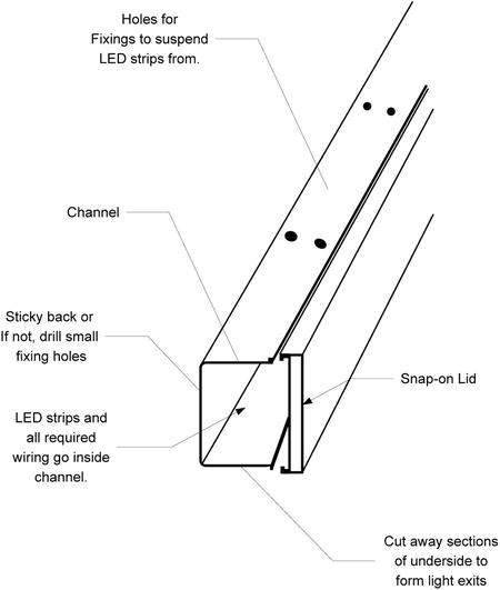
Figure 4-5. Waterfall light holder assembly
Figure 4-5 visualizes these points.
Having installed the LED strips into the channel I then got a 5 amp wire and ran it the length of the holder. This forms the +12-volt feed for the four LED strips and the far-end sensor. I cut each LED strip’s positive wire into this +12V feed wire. Of course, each cut-in point has to be taped up or shrink-wrapped to prevent any mishaps. In addition to the +12V feed wire, I then ran a six-way ribbon cable along the whole length of the holder and out the other side. The six conductors in this ribbon cable are used as follows:
- Wire 1 drops off at LED strip #1 and connects to its negative wire.
- Wire 2 drops off at LED strip #2 and connects to its negative wire.
- Wire 3 drops off at LED strip #3 and connects to its negative wire.
- Wire 4 drops off at LED strip #4 and connects to its negative wire.
- Wire 5 extends out to the far sensor and provides its “trigger” line back into the control box.
- Wire 6 carries a ground connection to the far sensor power feed, and to one side of its normally closed relay contacts. The +12V wire is also extended out to the far sensor to provide its power feed.
With the light holder assembly made, the next order of business is connections. The control box needed the following connection groups:
- A connector to bring in the signals from the light holder assembly—this had to be at least a seven-way connector. (+12V feed, four LED strip return wires, ground, and the far sensor trigger line).
- A connector for the near sensor—a three-way connector.
- A power connector to bring in 12V DC at about 2 amps. I decided that in the implementation, rather than having dual supplies or batteries it would be sensible to just feed the control box with +12V from a mains adaptor and have it incorporate a regulator that makes the MCU’s required +5 volts from that.
If you’re building your own version of this project you can decide to use whatever connectors you want, provided they can provide the right number of connections (as listed above) and each pole of the connector can carry at least one amp.
In my case, after initially considering a seven-way DIN connector from
- www.mouser.com (stock number 568-NYS323) (international)
- www.maplin.co.uk (stock number HH30H) (UK)
I decided to look for something with more connections, in case I decided to add more lights. I eventually settled on using a military style 14-way connector. I found out that these are very good quality and you can get the plug and socket for around $10 (delivered price) from several online sites. If you search for Y2M14-TK or Y2M14-ZJ you will find them for sale by many sellers2: you’ll also sometimes find them listed as “Aviation connectors,” “Y2M connectors,” or “CA-Bayonet connectors.”
If you do use one of these connectors, be aware that the plug hood has a left-hand thread, so you undo it the opposite way around (I wasted a couple of hours trying to figure that one out). Mate the plug and socket and while holding the locking collar tight with one hand, twist the cable grip clockwise (as viewed from the plug side) with the other hand.
Figure 4-6 shows a disassembled plug and the socket.
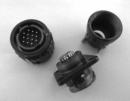
Figure 4-6. Disassembled plug and socket
For the near-sensor connector, I just used a five-way DIN plug and bulkhead socket that I had handy (though it only needed to be a three-way plug, strictly speaking). The DC plug was a standard DC jack to match the 2.1 mm pin plug that the power supply came with. Examples of DC jacks come from
- www.sparkfun.com (sku: PRT-10785) (United States).
- www.maplin.co.uk (stock number JK09K) (UK).
Obviously, you should match the DC power jack that you use to the one that is already fitted to your +12V DC power supply. I’m afraid that DC power jacks are bit of a minefield because there are so many different pin sizes and barrel depths. I always find it best to take the one I am trying to match to the store and make sure it fits, there and then.
The power supply I used for my installation was just a 12V 3-amp unit that I got cheaply from an auction site. The project only needs 2 amps really, but this power supply (originally made for a flat-screen computer monitor) was brand new, unused, and very cheap. It works really well. You may already have something similar that you could use, but if not, a suitable power supply should not be hard to find at a good price.
Having settled on the connectors and drawn up the final circuit diagram and connection schedule I got busy putting it all together. Figures 4-7 and 4-8 show the final circuit diagram, with connector details and a pictorial view of the connections and installation layout. These are only provided as examples as, should you decide to build something like this for yourself, you will probably have to vary the details to fit your installation, your requirements, and the connectors you use.
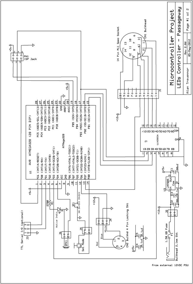
Figure 4-7. Circuit Diagram

Figure 4-8. Physical System Layout
The following summarizes points of interest in these diagrams:
- In the finished version, the ISP connector is now a six-way ISP connector consisting of two rows of three pins, not the breakout board that was used for prototyping on the test rig. This should be made with two rows of three header pins.
See Chapter 2 of Practical AVR Microcontrollers (Apress, 2012) for an explanation of ISP programming. Adding an ISP connector to this project makes it possible to update the controller’s software in situ, using your Pololu (or any other) ISP programmer. When viewed from the topside, this connector should be wired to look like Figure 4-9.
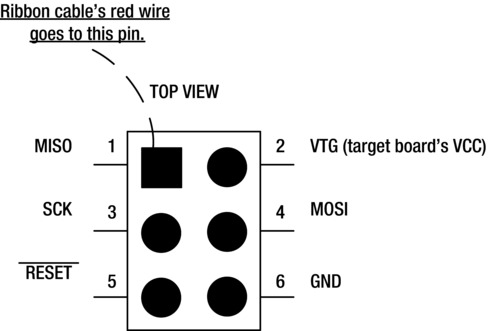
Figure 4-9. ISP connector details
- Note that, in this final version of the hardware design, the +5V regulator and associated capacitors have been added to allow the +5V supply to be derived from the +12V input.
- The +12V DC power supply coming in via the DC jack passes through a plastic cased inline fuse holder—inside the control box—before getting onto the board through a screw connector.
- The serial lines (TX, RX, and ground) are brought out to a three-way miniature screw connector. The signals from the near sensor (sensor 1) are also brought onto the board via a three-way screw connector.
- The signals coming in from the 14-pin mil socket are carried through to the board using a ten-way header pin strip and socket.
- The piezo electric speaker is held onto the side of the control box by two small bolts (see Figure 4-14). This results in a maximum loudness from it. You could drill a cluster of small holes in the box side to let more sound out, as I did, but I didn’t find that made much difference in the end.
Figures 4-10 through 4-16 show photos of the various built pieces and the finished result.
|
The sensors were both installed by fixing them to the wall with a small screw. Six-core alarm wire cable was used for the connections, though only three wires are used. The cable from the far-end sensor (pictured) was connected to the ribbon cable and +12V power supply inside the light holder assembly—as described earlier. |
|
The power unit was hidden away in a space under the stairs. A small hole through the wall allowed the DC side of the power supply (exiting left in this photo) to get to the control box (see below in this photo sequence). |
|
The box used was a plastic project box measuring about 5" x 3" (127 mm ´ 76 mm); holes were cut out of the sides for the 14-way connector, the DIN connector, the DC jack, and the push button (the button is shown in this photo at top right) |
|
The second view of the internals of the control box shows the connector mounts in more detail. The 14-way military connector is at left, then comes the DC jack for power, then the DIN connector used to connect the near sensor (sensor 1). |
|
This photo shows details of how the piezo speaker is mounted. Two nuts and bolts through the side of the box hold it captive by its edges. It needs to be able to flex in the middle to make the maximum volume of sound. |
|
This photo shows the control box installed high up, close to ceiling level. |
|
Close up on one of the light exits that are cut in the underside in the wire channel. These have to be approximately the same length as the light emitting portion of the LED strips used. |
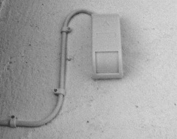
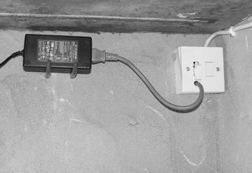
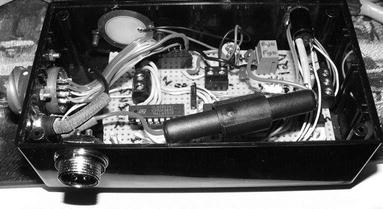
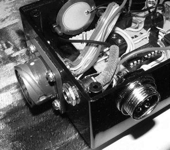
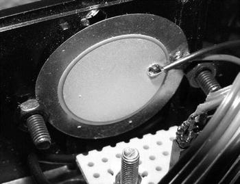
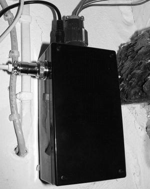
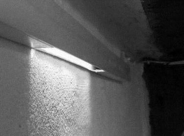
Figure 4-17 shows the lights all on, having just faded up in sequence—triggered by my approach.
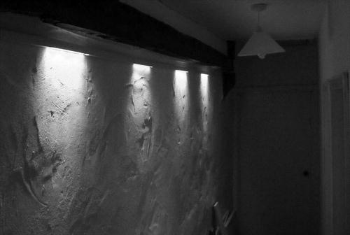
Figure 4-17. The finished effect
I might even get rid of that pendant light now!
Waterfall Lights Mark II
It’s always the way that, a while after something is made, you start second-guessing the design, the approach, the details—everything! In this case I haven’t torn it out and started again (yet) because the original works well and fills the need nicely. However, although the four-LED string version is very pretty, it’s not the waterfall I originally envisaged. So, I couldn’t help wondering how easy it would be to do the project a different way . . . so I have done a design for a Mark II version that uses more LEDs in smaller groups. It’s just a design, but here it is!
As you may remember, the reason that the first version ended up with four LED strips, rather than the six or eight I had originally envisaged, was that the ATmega328 (and in fact all of that series of AVRs), when used with the Arduino software, only offers four PWM outputs with rock-solid reliability. There are two others, but their PWM outputs are subject to contention with timer functions of the Arduino software which results in unreliable turn-offs and consequent possible timing problems. I also experimented with the softPWM library that is available from
http://code.google.com/p/rogue-code/wiki/SoftPWMLibraryDocumentation
That library allows you to use up to 16 pins as PWM outputs. However, although the library works fine with just a small main loop, when I added my code, I ran into problems. After a lot of head scratching and Googling, I was forced to the conclusion that something my code was doing was occasionally sabotaging the library code, making it do very sudden or jerky fades or just stopping altogether for seconds at a time. Just running the demo version alone was fine, but when I added my code, something to do with the timer functions I need to use was causing problems. It’s likely that someone with a deeper knowledge of the Arduino software than myself could resolve this, but I ran out of time and patience.
In the first version, I also needed to use a driver chip to drive the LED strips since the AVR cannot do this directly.
For the MKII version design I briefly considered using a chip called the M5450—which is a 34 output LED driver that has a serial input. The problem was that the M5450 does not do PWM, which I really wanted to keep in the picture. However, I clearly had to abandon the idea of using PWM direct from the AVR.
Then, a chip called the TLC5940 caught my eye. This chip (from Texas Instruments) offers the following facilities:
- 16 outputs—all offering PWM at 4096 different levels (much finer control than the 256 levels offered by the Arduino PWM).
- One common input sets the output current limit for all 16 outputs. This prevents outputs going over-current if there is a fault condition and protects the chip against damage.
- Each of the 16 outputs can (in theory) supply up to 120 milliamps—though it’s not clear whether you could use all outputs at that full amperage for very long without the chip shutting down due to an over-temperature error.
- The data specifying the brightness value for the 16 outputs is sent via a serial data transfer from the MCU to the TLC5940 using just four wires. Data can be sent at 30 MHz, which I think means that you could change the intensity of all 16 outputs around 150,000 times per second if your MCU could feed them that fast. Easily fast enough for a little bit of gentle fading in and out anyway.
- Various extra features such as slightly staggered LED turn-on times to minimize current inrush problems for the power supply, a facility to detect failed LEDs, a thermal error flag, and so on.
- Texas seems to have designed this chip with large-scale uses in mind. If you were building up a large matrix of LEDs as pixels in a picture or graphics display (such as you might see in a stadium or public mall) you would probably be very concerned about even quite small differences in the brightness of individual LEDs within your display. Using PWM techniques does tend to heighten such differences. So, if you’re trying to build up a picture on a LED matrix and you can’t precisely control each pixel, then you will have problems. Therefore, the other major functional block of the TLC5940 is a dot correction EEPROM which allows you to make and store a PWM correction factor for each output so that you can exactly match the output to the individual LED that is connected to it. In our application this whole area is of little interest to us, since we are using the LEDs as lighting, not as picture elements: so, we leave that block of functionality disabled. Be aware that if you did want to use this side of the chip, you would need a +22V “programming voltage” to be able to reprogram the intensity correction EEPROM.
- The ability to cascade devices. If 16 outputs is not enough, you connect two or more TLC5940s in series and you can add sets of 16 lights, so start with 16 then go to 32, 48, 64—or whatever.
This one chip could solve the PWM problem with the first design and also eliminate the need to use the ULN2803A that was required for the first version. If you’re thinking of getting one of these to try out on a breadboard, make sure you order the TLC5940NT—where the NT denotes the DIP package: The device is also available in a couple of surface-mount packagings which you won’t be able to use on the breadboard.
Full details of the TLC5940 can of course be seen in its data sheet; go grab a copy from
www.ti.com/lit/ds/symlink/tlc5940.pdf
However, be warned, it’s not the most approachable piece of technical documentation you’re ever going to read! In fact, lucky for us, that doesn’t matter. Alex Leone has created an Arduino library to take most of the pain out of driving the TLC5940 for us. See details and download information at
http://code.google.com/p/tlc5940arduino/
http://alex.kathack.com/codes/tlc5940arduino/html_r014/
When using this library, you connect your AVR to the TLC5940 using the pins that the library requires, or you can try using other pins if you prefer. The file tlc_config.h is where you can make those changes. See the “files” tab on the second of the web sites mentioned previously. The library comes with numerous example programs. Using this library you can cascade up to 16 chips, giving a possible total of 256 individual LEDs or clusters of LEDs. If you’re prepared to go in for a little LED multiplexing, then you can use TLC5940s to control an enormous number of LEDs.
The installation documentation tells you to install the library into the libraries subfolder of your Arduino sketchbook folder. However, I found that when I did that (on Windows or Linux) that I got compile errors when I tried to use even the demo programs; this was under Arduino release 0.22.
However, when I installed the library into the main installation hierarchy it all worked fine. Since the library was created in 2010, it might be that subsequent Arduino updates have created this problem, but anyway the fix for this, if you do get the problem, is to install in the library subfolder that you will find under your installation location: on Windows XP it’s
C:Program FilesArduino-xxx
where xxx is the Arduino version number. Under the installation location you will find a folder called libraries which is where you should install the TLC library, in its own subfolder. On Vista and Windows 7 you will need to have administrator privileges to do this installation. It’s not a problem on Windows XP or earlier.
On Linux and on Mac OS X you’ll find the base directory for Arduino at
/usr/share/Arduino
Under the installation location, you will find a directory called library and you should install the TLC library there under its own subdirectory. On Linux or Mac machines you will need to use the sudo command or login as the superuser to acquire the privileges required to do this installation.
If your Arduino installation is, for some reason, nonstandard and you can’t find the Arduino software set, a simple trick is to look at the properties of the clickable link that you usually use to run Arduino. Those properties should show you where the software was installed.
The downside of having to install the library under the installation folder is that, when you upgrade your Arduino software, if the old version is removed, you will also lose any custom libraries you have installed in this way. Therefore, keep copies of downloaded libraries somewhere safe, so that you can reinstate them after future upgrades if need be.
So, an MKII design using the TLC5940 would have a lot of possibilities. It would be possible (although an absolute wiring nightmare) to use a large number of individual LEDs and to have them fade one at a time. Or, we could use 5050 series RGB LED strips, and use multiple TLC5940s to drive them in various different sexy ways. The temptation to go overboard is very great. If we were we creating a disco light show or something of that kind, those would be very good options, but with our feet firmly on the ground we have to repeat the calming mantra “Passageway Lights” over and over again.
Take-Two Circuit Diagram
In the end, I decided to stay with a relatively simple scheme of up to 16 single-color LED strips, with the ability in the software to use as many or as few of the 16 as required. Figure 4-18 shows the circuit diagram.
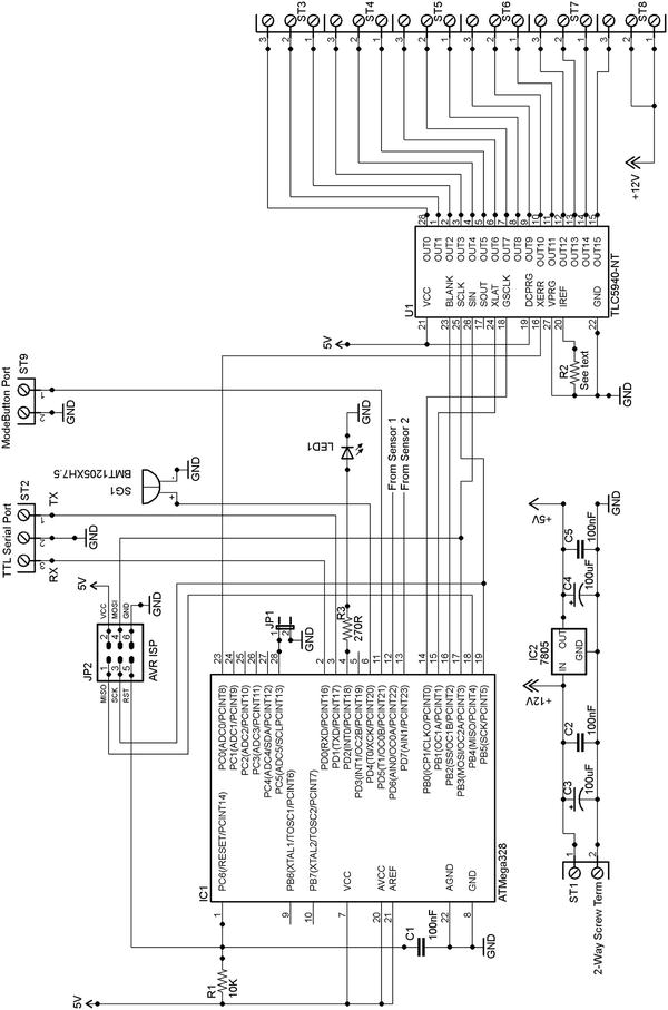
Figure 4-18. Mark 2a passage lights circuit diagram
In this circuit diagram (intended to be built up as a stand-alone project, not a test rig project) the default pins, as specified in the TLC5490 library, drive the device. Most of the other peripherals from the previous iteration (the tone sounder, the mode switch, the sensors) connect via the same pins as before: the exception is the jumper, which now connects via Arduino’s pin A5 (pin 28). Note also that the XERR pin of the TLC5940 is connected to A0 of the AVR (pin 23) this gives you the possibility of checking every now and again as to whether the 5940 has detected any LED errors.
The 5940’s outputs are extended out to miniature screw connectors. You would connect each set of LED strips with its positive lead to one of the +12V leads and its other to whatever output of the 5940 you needed.
R2 on this diagram is connected to the IREF pin of the TLC5940. This pin is used to set the maximum current output that can be drawn from each of the output pins. You connect the pin to ground through a resistor and the current it pulls is used to determine the current limit the chip will apply to each of the outputs. The value of the resistor is determined by the following formula:
![]()
For example, if you want the max current to be 80 milliamps (0.080 amps) this becomes
![]()
So, in such a case you would probably use the nearest preferred resistor value, which is 470 Ohms.
The TLC5940NT needs a constant frequency square wave into its Grayscale Clock (GSCLK) input on pin 18. This signal is used as the master reference clock for all of the chip’s PWM operations. In the default hardware configuration, instanced by the TLC5940 library, the AVR’s pin 5 (Arduino pin D3) is set to give out a constant PWM pulse (at about 500 Hz) to provide this, and that arrangement will work well. However, rather than sticking with that, I perversely decided to extend out the AVR’s 8 MHz clock, just to see if would work—and it does!
The AVR ATMEGA328 has a feature whereby its system clock can be extended out to pin 14 (Arduino digital pin 8). When used in this mode, the AVR calls this pin CKOUT; if you program the CKOUT fuse, whatever clock the AVR is using is enabled to be output on the CKOUT pin. This applies whether you are using the internal 8 MHz clock (as we are) or an external crystal—as detailed in Chapter 3 of Practical AVR Microcontrollers (Apress, 2012). This CKOUT feature allows you to use the same clock frequency for all devices in your project. In this case it’s the TLC5940.
To extend out the AVR’s internal clock, we use AVRDude (see Chapter 3 of Practical AVR Microcontrollers [Apress, 2012] for extensive details and examples of using this useful program) to reprogram the fuse bit. So, how do we use AVRDude to program the AVR chip to activate CKOUT? Well, as we saw in Chapter 3, the format of the FLB is
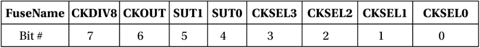
So, in this context, bit 6 is the one of interest. We start by using AVRDude to find out the current value of the fuse. Assuming that the fuse is at its default state, we will need to invert it to turn on CKOUT.
![]() Tip In the following command sequence you will have to ”plug in” your own comms port (e.g., COM2 or /dev/ttyACM0). You will have to change the DESTination to CON for Windows or “-“ (meaning standard output) for Unix. If you are not using an ATmega328p chip but some other AVR variant (e.g., an ATmega328), you will have to change that value too. See the section “AVRDude” in Chapter 3 of Practical AVR Microcontrollers (Apress, 2012) for lots more details on these areas.
Tip In the following command sequence you will have to ”plug in” your own comms port (e.g., COM2 or /dev/ttyACM0). You will have to change the DESTination to CON for Windows or “-“ (meaning standard output) for Unix. If you are not using an ATmega328p chip but some other AVR variant (e.g., an ATmega328), you will have to change that value too. See the section “AVRDude” in Chapter 3 of Practical AVR Microcontrollers (Apress, 2012) for lots more details on these areas.
Begin by opening a command (terminal) window on the desktop machine to which your AVR and programmer are connected.
Now, make sure AVRDude can “see” your AVR chip.
avrdude –p m328p –c avrisp2 –P {YOUR_COM_PORT}.
This should make AVRDude print out the signature bytes of your AVR and make it verify the fuses. Next, make AVRDude show you the current lower fuse byte value
avrdude -p m328p –c avrisp2 –P {YOUR COM PORT} –U lfuse:r:DEST:h.
This will show you—in hexadecimal format—the current value of the lower fuse byte. You can decode it using the bit layout diagram shown previously; or, if you prefer, you can use the online fusecalc site at
www.engbedded.com/fusecalc
to do it for you. On that site you enter your AVR part number, or use the nearest one to it, if you can’t find the precise one (e.g., if you have an ATmega168-P just use ATmega168). Then, enter the value returned by AVRDude into the LFUSE box near the bottom of the calculator and you will see the tick boxes change to the settings represented by the code you just entered. Change the value of CKOUT using the tick box and you will then see the new value you need to program.
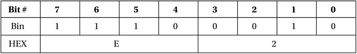
Remember that a “programmed” (active) bit in an AVR fuse is read by AVRDude as 0 and an unprogrammed (inactive) bit will read as a 1. This is the opposite way round to most logic systems. So, suppose that AVRDude returned the value xE2 (assuming you unprogrammed CKDIV8—bit 7—earlier in the book to get your MCU running at 8 MHz) you would just need to invert bit 6 and make that into xA2. In other words:
Becomes
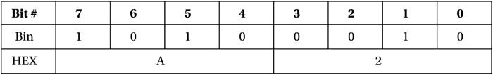
We program the required value into the fuses, using the command
avrdude -p m328p –c avrisp2 –P {YOUR COM PORT} –U lfuse:w:0xA2:m.
And that’s it! You should have a steady square wave clock coming out of what is now the CKOUT pin of your MCU. This technique is useful over and over again in designing MCU projects because it saves you having to provide separate circuitry for clocks to other devices—which usually means adding extra devices onto an already crowded board.
As of this writing the MKII project is just a proof of concept on a breadboard, and it seems to work okay there just using individual LEDs as proxies for LED strips, though for some reason that I don’t understand I did have to reduce the IREF resistor lower than the equation suggested to get a good brightness. I’ve done a rough and ready conversion of the software for the MKII which is available through the book’s web site (www.apress.com/9781430244462).
As a final word, the diagram in Figure 4-19 shows how you connect up two TLC5940s in a chain to give yourself more than 16 outputs. This is not a full waterfall lights diagram; it just shows you how to chain up your TLCs! Don’t forget that, to use a circuit like this with two TLC5940s, you will need to edit the file tlc_config.h to change the value of NUM_TLCS. As stated earlier, you’ll find that file in the same folder as the other TLC5940 library components.
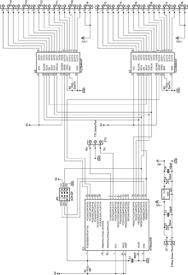
Figure 4-19. Dual TLC5940 Basic Circuit
Summary
In this chapter we have looked in detail at how to build a useful home lighting project—one with several novel features. We have looked at some different options for how to make it and some possible alternative electronic approaches. We’ve also seen how an MCU subsystem can gain the ability to respond to external commands. In this way, something that might once have been simply a standalone item, could in fact—with the proper infrastructure provided—participate in a wider, more coheseive whole-home control system.
Coming Up Next
Project 5: Moving to Mesmerize.
__________________
1Such products are a very cheap source of LEDs by the way, if you are careful with your desoldering.
2If you want different number of poles, you’ll find these Y2M series connectors go up to very large pin counts. Check out the Y2M-65TK!