
![]()
Project 2: Crazy Beams—Exercise Your Pet!
In this project we are going to try to give your pet (your cat or your dog) hours of harmless fun and exercise. This project is a little like the gem light project covered in Chapter 4 of Practical AVR Microcontrollers (Apress, 2012). This time, though, we’re not out to do something ornamental; this time we have a functional aim in mind: keeping the animals entertained!
The idea for this project came from observing how much fun it can be to watch a cat or dog trying to catch the light spot cast from a presentation pointer. You’ve seen these things; they are very low-powered laser lights, usually no more than 5 mw and often built into a pen or a key ring. They are used to put a pinpoint of red light on a screen—usually to indicate a point or area of interest during a live presentation that uses a computer or a stills projector. A dog or a cat will happily spend a long time skittering around the floor chasing one of these light spots, while you, sitting comfortably in your chair, shine the light all around the room. The animal pounces on the light spot triumphantly. But then, the light spot escapes its grasp and it’s off again. Then the light disappears altogether. Where has it gone? It’s behind you! Your dog or cat can have hours of fun. The trouble is that the human wielding the pointer light usually gets tired of the game before the animal does!
So, what if there was a machine to do the light shining? One that could move the light around, casting multiple light spots, randomly speeding up and slowing down, making the light disappear and reappear again somewhere else. Endless fun! And, since a machine never gets tired, it goes on and on until the animal has had enough!
The Project
This project uses two very low power lasers attached to two servo motors. These motors allow the beams of light to be moved around in the horizontal plane. However, the laser and motor assembly are mounted on a spindle which allows them to be moved in the vertical plane by a third motor; this allows the AVR controlling the whole thing to move the beams around quite a large area.
The second laser and its associated motor are optional, you can just build the project with one laser and servo motor if you want to. Although the effect is better with two beams, the software doesn’t care if any (or all) of the motors are not really there. Commodity-priced servo motors don’t offer any positional sensing capability to the host computer, so unless you use far more expensive motors the Crazy Beams software has no way to sense the motor positions. This is not a problem, however; as covered in Chapter 4 of Practical AVR Microcontrollers (Apress, 2012), servo motors are pretty good at doing what they’re told!
If you have multiple animals to entertain, you could add a third or even a fourth motor and laser. That would make lots of beams for your pets to chase. If you’re scaling up the project in that way, though, you need to make sure your power supply arrangements are sufficient. The power requirements for each laser are low, but each additional servo motor adds quite a lot to the power supply load. Scaling up the project from a hardware point of view is not hard; there are lots of spare I/O pins on the AVR MCU chip and the software makes use of a motor descriptor array which can be extended.
Another way to scale up the project without extra motors and lasers would be to add prismatic diffusers, to split the beams multiple ways, although at reduced intensity. You can get some very pretty room lighting effects in this way too, but that’s beyond the immediate scope of this project.
Presentation pointers that incorporate low-power laser diodes are widely sold and cheap, so my first thought was to try to extract the laser diodes I needed from two of these. Having tried this, I can’t recommend that approach. The problem is that those kinds of products are really not meant for disassembly: they seem to be put together as a friction fit under a lot of pressure. That means that you have to cut your way into them, making jagged edges and (in my case) deforming both the lens assembly and the laser diode in the process. My laser didn’t focus properly afterward and stopped working shortly after that. So, on the whole, pillaging a presentation pointer for its laser module seems like an unexpectedly tricky job that could take a lot of tries to get right!
Fortunately, you can buy just the laser diode and lens assembly separately and ready wired for use with a power supply; it does cost a little more, but it’s ready to go when you get it—and this is the route I eventually took.
Example products can be found at
- www.sparkfun.com/products/9906 (United States).
- www.maplin.co.uk (UK) (search for LE07).
You can also get these from various eBay vendors (search for “laser diode module”). Make sure you get +4.5V or +5V lasers, which will simplify your power supply arrangements. Don’t get anything more powerful than 5 milliwatts because it will be too bright and possibly dangerous to your eyesight.
![]() Caution Never regard a laser as harmless. Using one with the recommended power level is as safe as we can make it, but do not ever shine the laser directly into your own eyes or anyone else’s. Sight damage will occur. Also, make sure that the laser stays slightly unfocused when you set up your Crazy Beams project. This will diffuse the laser light slightly so that your pet’s eyes, if they happen to look at the unit, cannot be overexposed.
Caution Never regard a laser as harmless. Using one with the recommended power level is as safe as we can make it, but do not ever shine the laser directly into your own eyes or anyone else’s. Sight damage will occur. Also, make sure that the laser stays slightly unfocused when you set up your Crazy Beams project. This will diffuse the laser light slightly so that your pet’s eyes, if they happen to look at the unit, cannot be overexposed.
The lasers I used consume about 40 ma each, which is not a lot, but about twice as much as you would want to take from an MCU pin.1 So, we have to include our old friend the 2803 transistor array chip (see Chapter 3 of Practical AVR Microcontrollers [Apress, 2012]) to provide the drive that the lasers need. You could use just use NPN transistors, such as a couple of BC548s if you prefer—but by the time you’ve added a base resistor they’d probably take up almost the same amount of board space.
Project Build
The project consists of three major assemblies.
- A simple wooden frame.
- The horizontal motor/laser assembly
- The electronics board. You could build it on a mini-breadboard, but you could easily make a solder board version of it—it’s really just two chips.
The frame has to be fairly deep, but not very long or high. So, I made this up out of some short lengths of 7" (180 mm)-wide pine plank (see Figure 2-3).
The horizontal motors frame is made from a couple of stiff plastic strips (something suitable in plastic or metal can be obtained from your usual home supplies superstore) and a couple of thick wood blocks (I used some short lengths of 2"-square table leg that I had left over from a previous project).
The horizontal assembly is mounted on a spindle so that it can swing back and forth. The spindle is made from a couple of 0.25"/M6 bolts which clear through the sides of the frame and then loosely fit into some appropriately sized threaded inserts, which screw into the side of the blocks. Figure 2-1 shows a threaded insert (see the “Secret panel” project in Chapter 1 for more details and links to where to get them).

Figure 2-1. Threaded insert
The horizontal motors are mounted on the assembly and the lasers are mounted to the top of those motors. This means that the motors can sweep the laser lights that they carry back and forth to move the light spots in the horizontal plane. Figure 2-2 shows the completed assembly with the two servo motors mounted in place but no lasers fitted yet; you can see a threaded insert at the end of the assembly. There is no “right” size for this assembly because the size depends on some variable factors:
- Whether you are going to use two horizontal motors and lasers (as per the picture) or just one.
- How far apart you want the traveling light spots to be. If you have several pets to amuse, it may be that you want greater separation, in which case the motors will need to be mounted wider apart to increase the distance. You may also want space for scaling if you have more additional pets to amuse and want to add more horizontal beams.
- The maximum rotation of your servo motors—as covered in Chapter 4 of Practical AVR Microcontrollers (Apress, 2012) there is actually some quite surprising variation in this supposedly “standard” factor.
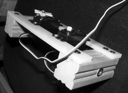
Figure 2-2. Completed horizontal assembly
Obviously, a little servo motor pushing and pulling is going to have a much easier job if the horizontal assembly swings freely. It’s therefore pretty important that you make sure to place the threaded inserts as centrally in the end blocks as you can get them.
When you put all this together you should have a free-swinging assembly that the vertical motor (via the linkage mentioned earlier) can easily move to and fro, under control of the MCU. Don’t over tighten the bolts through the threaded inserts, and make sure the clearance holes through the frame sides are just large enough to allow the bolt to rotate freely.
The vertical motor is built onto the frame, raised up by appropriately sized wooden blocks—as shown in Figure 2-3. The motor needs to sit at a height where, via a linkage made with stiff wire bent into shape, it can push and pull the horizontal assembly back and forth, affecting the vertical position of the laser spots. It doesn’t have to provide a large amount of movement, since a small change in the angle of the lasers makes quite a big difference to the beam’s position. The software on the prototype only needs to move the vertical motor over about 30% of its possible travel, and this makes a perfectly adequate difference to the beam positions.
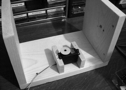
Figure 2-3. Crazy Beams project frame (vertical servo motor in place)
You could, if you wanted to make the project “disappear” better, paint the frame in black or some other darker color. I left mine white, since it lives in my office/workshop area so appearance is not a big issue.
Before you begin assembly it’s a good idea to make sure that each servo motor you plan to use is reset to its zero degrees position. This is essential for getting the laser mounting right and for getting the wire link set up correctly.
I’ve found that some motors reset to their zero position as soon as you connect their voltage pins (almost always black and red wires) to a +5V source, but leave their servo lead (usually either white or yellow) disconnected. Some motors don’t reset, though, and for these you should use the servo motor reset program (you can also download this program from the book’s web site (www.apress.com/9781430244462). To use this, you’ll have to jump ahead a bit to the circuit diagram in Figure 2-7 and Figure 2-8 and connect your motors up as shown there.
The servo reset program is very simple, as follows:
/*
 Servo Motor Reset Program:
 Reset all listed servo motors to zero degrees
 */
#include <Servo.h>
#define HORIZ01_PIN 6
#define HORIZ02_PIN 9
#define VERT01_PIN 10

Servo horiz01;
Servo horiz02;
Servo vert01;

void setup()
{
  Serial.begin(9600);
  Serial.println("Resetting motors");
  horiz01.attach(HORIZ01_PIN );
  horiz02.attach(HORIZ02_PIN );
  vert01.attach(VERT01_PIN);

  horiz01.write(0);
  horiz02.write(0);
  vert01.write(0);
  Serial.println("Reset done");
}

void loop()
{
  // Main loop left intentionally empty!
}
This servo reset program just uses the servo library (see Chapter 4 of Practical AVR Microcontrollers [Apress, 2012] for details) to set each motor to zero degrees; it uses only the setup() function, and the loop() is empty. When you upload and run the program, you may find that nothing appears to happen. This could mean you have not wired up the motors correctly, but more likely it means that the motors are already at their zero degrees position. To be sure, try temporarily changing the
"...write(0)"
lines to something like
"...write(100)"
and try again. That should make some movement, if your wiring is right. Don’t forget to change the code back to zero and run it again to make sure your motor is reset to zero degrees before you install it. The main program for this project also includes numerous features that can be useful during setup and alignment of the mechanical elements. See the section “Crazy Beams Software Code Walk.”
It’s important that you make a note of which way your motor turns when it goes from angle 0 to angle 100. You’ll need this information to better visualize positioning the laser diodes and setting the linkage from the horizontal assembly to the vertical motor.
Once the motors are reset you can begin mounting the laser modules on the servo motors. I used the longest and widest of the horns (the plastic wheels and fittings that usually come with the motor are the “horns”) and some 22 SWG2 (0.7 mm) tinned wire to bind the lasers to it. You can use various kinds of wire for this purpose—piano wire or garden wire might be suitable. Any metal wire in the range 20 SWG to 25 SWG should work well.
You need to bind the laser to one side of the center so that you can still access the center screw on the horn to tighten it up. The photo in Figure 2-4 shows how this looks when it’s done. Twist the wire up tight with a pair of pliers. Make it tight enough to hold the laser very securely, but don’t go crazy. The wire will snap or the laser casing might deform. The wire actually does hold the lasers very securely; however, when the setup alignment is done, you can put a dab of glue between the plastic horn and the laser module to make extra sure it stays in place—but don’t do that before you have aligned the laser.
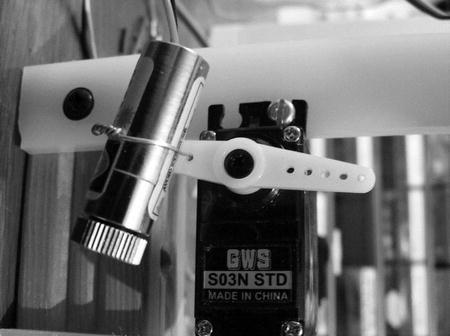
Figure 2-4. Laser diode mounted on servo motor
The next job is to install the linkage from the vertical motor to the horizontal assembly. Mount it so that, with the vertical motor at its reset position, the horizontal assembly is held such that the laser light will just shine inside the frame. This gives the software the ability to reset the beams so that they don’t leave the frame. The linkage from the vertical motor to the horizontal assembly is made of a dual strand of 22 SWG (0.7 mm) tinned steel wire—again, you can use anything comparable. As long as your horizontal assembly swings freely this linkage should be plenty strong enough. You’ll need a small hole through the lower plastic crossbar so that the linkage has a good anchor. As before, the vertical motor is fitted with the longest of the plastic horns it came with (this maximizes the swing the motor can exert).
Figure 2-5 shows the linkage in place, in this photo the motor is set at about 70 degrees of travel; when it’s set to less, the motor will turn counter clockwise and pull the assembly back toward us, lowering the vertical setting.
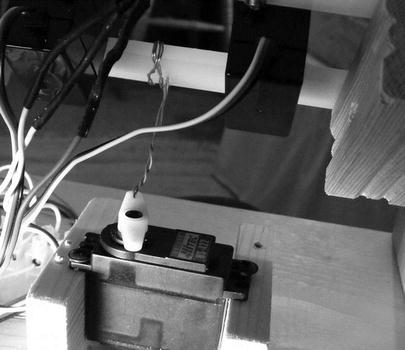
Figure 2-5. Vertical motor to horizontal frame linkage (see also Figure 2-6)
Figure 2-6 shows the overall assembly.
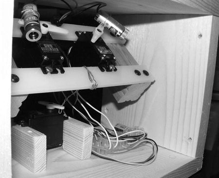
Figure 2-6. Overall view of the Crazy Beams project
As long as you have made sure the motors are all reset to their zero degrees position, aligning the lasers is quite straightforward. You just need to put the horn on the motor such that the laser will point to a base position when at its “at rest” position. We can handle the rest of the positioning issues in the software (see “Crazy Beams Code Walk” section – below).
The diagram in Figure 2-7 shows the electronics for this project. This diagram is broadly the same however you elect to build the electronic side of the project (breadboard, solder board etc).
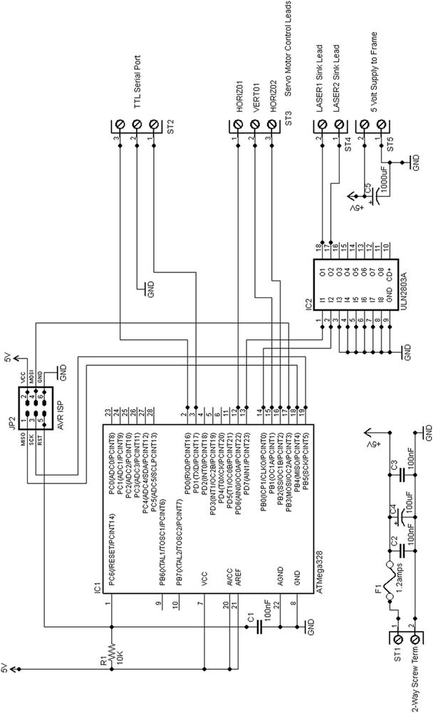
Figure 2-7. Crazy Beams main circuit diagram
Note that because we are using motors, a fuse is a must-have: you need one somewhere in the + lead of the power supply.
We are again using a trusty ATmega328 chip. We are using it in its internal 8 MHz clock mode (see Chapter 3 of Practical AVR Microcontrollers [Apress, 2012] for details on using AVRDude to set up this mode of operation) which is plenty fast enough for this application. In addition (as previously mentioned), we need a ULN2803A driver transistor array,
Table 2-1 shows the AVR pins we use here.
Table 2-1. AVR Pins Usage
|
AVR Pin Number |
Arduino Name |
Usage |
|---|---|---|
|
2 |
RXD |
Receive data |
|
3 |
TXD |
Transmit data |
|
12 |
Digital pin 6 |
Horizontal Motor 1 Servo Control Line |
|
13 |
Digital pin 7 |
Laser1 (HIGH = ON) |
|
14 |
Digital pin 8 |
Laser2 (HIGH = ON) |
|
15 |
Digital pin 9 |
Horizontal Motor 2 Servo Control Line |
|
16 |
Digital pin 10 |
Vertical Motor 1 Servo Controller Line |
As previously discussed, this leaves lots of spare I/O pins free for adding more beams and motors.
Because they are electromechanical devices, even the comparatively well-behaved servo motors can be quite brutal to a power supply (as compared to purely electronic devices). Therefore, we add a couple of 1000 uF capacitors to the circuit in this project to better protect the logic circuits against power supply dips and spikes. C5 goes onto the main electronics circuit board (test rig) and the other, C6, goes inside the crazy beams frame box. One effect of adding this extra capacitance is that the rise time of the power supply will increase; that is, the time it takes at switch on for the PSU to reach +5V from nothing will be increased. This can cause problems with AVR reset. So if, after you add the capacitors, your AVR never (or sometimes doesn’t) starts up, you may need to increase the value of C1 (e.g., to 0.47 uF) to make the power-on reset pulse at the AVR’s pin 1 a little longer. That should solve the problem, if it occurs.
The power arrangement shown in the circuit diagram assumes that everything runs off +5 volts, which it probably will. Most small servo motors run on +5 volts as do the specified laser diodes. However, if you somehow end up needing a +12V supply as well, just reuse the power supply design from the sliding panel project from Chapter 1, which will do the job nicely.
As you can see, the connections to the crazy beams frame come off the board via seven screw connector terminals (not including the TTL level serial port, which you can optionally use for this project as you’ll see when we get to the software description). Unless you’re building a custom board that can live inside the frame, you’ll need to make up a seven-way wiring harness to convey the signals from the board to the frame. You’ll see in the photos how I did this; I just used a miniature plastic screw terminal inside the box.
The diagram in Figure 2-8 shows the wiring inside the project’s wood frame. The essential connections are as follows:
- +5V to the + lead of each motor, and also to the positive side (red wire) of the two laser diodes.
- Ground connects to each motor (note: C6 doing the smoothing function described above).
- Each motor’s servo lead is brought back to the board individually.
- The negative lead of each of the laser diodes is brought back individually to the board.
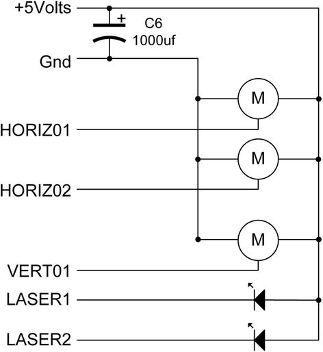
Figure 2-8. Motors and laser wiring
It’s tempting to want to make the wiring run between the electronics and the frame as long as possible, but although I haven’t tried it, I think that you might start to run into noise problems if the wires were more than about 18 inches.
That concludes the description of the physical aspects of the project. Let’s now move on to the software.
The software for the Crazy Beams project is currently version 3. I did two previous versions (how did you guess!) but scrapped them due to various defects and shortcomings.
The final version uses a data structure (servoMotorDetails) to describe the properties and current state of each motor. An array instance of this data structure, motors, holds the descriptions of the servo motors and their state (see next section “Software—Positioning Parameters and Timing Constants,” for more details). Various functions within the program play around with the contents of this array, and then they call setMotorAngles(), which is the only function in the main part of the program that writes to the hardware.
The main two components of the loop() function are to generate a random number which, based on the number generated, can change the pathways of the crazy beams in some random way. We’ll see details of this in the section “Crazy Beams Software Code Walk.” The other component of the main loop is just to progress the “animation” of the laser beams. They basically scan back and forth and a little bit up and down—which would get boring after a while, but the random number handler’s actions break it all up and make the beams suddenly do something different. There is no predictable pattern to the pathway of the beams—they are, literally, crazy! Also within the main loop we check to see if any single letter commands have come in from the serial channel.
Software—Positioning Parameters and Timing Constants
Just before we take a code walk, it might be helpful to explain in a little more detail the function of the constants and values declared at the start of the Crazy Beams software.
In this project, we don’t use the full rotation of the servo motors; we only need to use a part of each motor’s rotational range to get the effects we want. However, that range will vary from build to build, affected by mounting arrangements, distances between motors and frame, and beam length. So, each motor has the following parameters associated with it. These are stored (along with some other items that add to the description of each of the three motors) in an array of C-structs called motors, which is of type servoMotorDetails.
- restAngle: This is the angle the motor will be set to when the project is not in use, or during initial reset.
- startAngle: This is the “home” position for the motor; it is the start point of its useful rotational range within this project.
- endAngle: This is the maximum rotation we need the motor to do within the context of this project. If the motor rotates further than this, then the laser (or mechanical linkage it controls) may hit something, or a beam may shine somewhere we don’t want it to. The software will never send the motor beyond this point.
- maxAngle: This is the maximum angle to which the motor is capable of turning. It is never used by this software.
- currentAngle: This is the angle to which the motor is currently turned.
Two timing constants control the beam travel speeds: LOOP_DELAY_MIN and LOOP_DELAY_MAX. In the main loop, after each beam move, the program delays for a few milliseconds. One of the randomly chosen actions in the main loop is to change this timing value to a random value in order to make the beams move faster or slower. These two constants constrain the randomly chosen timing value to a range that makes sense for this application.
Crazy Beams Software Code Walk
The Arduino code for Crazy Beams is downloadable from the book’s web site (www.apress.com/9781430244462). The code walk shown in Table 2-2 explains all the functions within the program.
Table 2-2. Crazy Beams Software—Functions List
|
Function |
Commentary | ||
|---|---|---|---|
|
Declarations Header Section (args: none) |
In this initial section, the Arduino pin numbers for the motors and the lasers are defined and various constants are declared. This section also includes the servo library, which is what we use to provide the PWM values needed by the motors. The servoMotorDetails struct is declared, and the motors array filled with a mixture of constants, initial values, and references to instances of servo motors. Note that mtrsArrayTop needs to be declared here because, in Arduino’s environment, there is no easy way for software to dynamically discover the upper bound of an array. This tells the rest of the program the highest index number of the motors array. | ||
|
setup() args: None |
The setup() function attaches the relevant pin numbers to the servo motor object instances. It then sets the motors to their rest position, then to their end positions, back to the rest position, and then finally to their start positions. This is intended to ensure a full mechanical reset and to ensure there are no blockages to movement over the full required movement range. Essentially, the theory is that users get used to how a machine resets, and if anything sounds different than usual they will investigate it before too much damage is done. Nice theory! Next, the laser pins are initialized and the lasers flash quickly four times to show they are okay. Finally the version message is sent out to the serial channel. Usage of the serial channel in this project is optional. However, having a TTL level serial USB dongle on a laptop or desktop does give you extra control over the unit. See Chapter 2 of Practical AVR Microcontrollers (Apress, 2012) for more detail on USB serial dongles. | ||
|
loop() args: None |
As previously described, the main loop of this program progresses movement of the horizontal beam motors and the vertical motor in a nice smooth fashion; each one will scan from its start position to its end position and back again, over and over. The code to do this is located near the end of the loop() function. However, in order to get to that, the processor has to get through a number of preliminaries.
Next, we generate a random number. In the program as-supplied, this random number will be between 0 and 199. Most of the numbers in the range don’t have any effect. However, within the main loop there is a list (in a switch-case set) of numbers that do cause changes to the beam paths to be made. Note that the beam path changes are made by changing items in the motors array, not by directly writing to the hardware. The contents of the array are used to write out positioning commands to the hardware, only at the very end of loop(). The random number matches do the following things:
|
||
The effect of injecting this randomness is that the beams will move around smoothly for a while and then suddenly change course or speed. Then they disappear and shortly afterward they reappear somewhere else. If you want less randomness, just increase the higher value in random(0,200) from 200 to a larger number. This makes it less likely that any of the defined numbers will come up in a random selection. Decrease it (no lower than 10 though) if you want even more randomness. Finally, we call the functions to progress the horizontal and vertical motion, and it is these that actually call the setMotorAngles() function, which positions the hardware according to the contents of the motors array. | |||
|
motorsHome() |
These functions all do similar things. They position each of the motors to a known position, such as its rest position or its end position. These were described in the previous section of the text. None of these functions take any arguments, or (since there is no sensory feedback from the servo motors used) return any values. |
||
|
turnOnLasers() turnOffLasers() args: None. Return values: None |
These functions turn both lasers on or off. They take no arguments and return no values. |
||
|
progressHorizMotion() progressVerticalMotion() args: None. Return values: None |
These functions progress the motion of the horizontal and vertical motors. They manipulate the contents of the members of the motors array that relate to the horizontal motors. For each horizontal motor the following processing is performed:
At the end of this processing, the motor position has been moved on by one step, and a reversal of direction made, if needed. Finally, the motor values are written out to the hardware using setMotorAngles() |
||
|
horizontalMotorRandom() verticalMotorRandom() args: None Return values: None |
These functions set the currentAngle member of each motor’s entry in the motors array to a random value. The random value will be somewhere between the motor’s startAngle and endAngle values. |
||
|
setMotorAngles() args: int motorID |
This function sets the angle of one or more motors, as defined in the motors array. It takes one argument, motorID, which is an integer that defines which member of the motors array is to be used. However, if motorID is sent as -1, then all motors are set. The currentAngle values held in motors are assumed to be in range and valid. This is the only point in the program where the motor positions are directly set from the software. All other functions that want to set the motor positions modify values in the motors array and then call this function. |
||
|
lasersOn() lasersOff() args: None Return values: None |
These functions turn both lasers on or off. |
||
|
changeLoopDelay() args: None return Value: None |
This function changes the global variable loopDelay to a random value between LOOP_DELAY_MIN and LOOP_DELAY_MAX. As mentioned previously, this has the effect of changing the beam progress speed by changing the time delay in the programs main loop. |
||
|
processKbInput() args: None Return value: None |
This function is called from the main loop when it recognizes that something has been received from the serial channel. This gives a way for a user (using a TTL serial port on another computer) to exercise control over the Crazy Beams unit, and to see the message stream coming out of the unit. This function implements a number of single-character commands. Commands are not echoed and can be lowercase or uppercase, either will work. The commands are as follows:
|
So, that concludes our code walk for Crazy Beams, and indeed the project description.
Summary
This chapter has detailed the design, mechanical construction, electronics, and software of a Crazy Beams project. This is a project that is intended to provide unending entertainment for your pets, by giving them beams of light moving around the floor that they can chase, but never catch! If you are building the project you should take due note of the safety messages in the text around laser usage and fusing. The project is readily adaptable to a variety of configurations, either less or more complex (e.g., depending on the number of pets you have to entertain).
Coming Up Next
WordDune; a game of words.
__________________
1In fact an ATmega328 pin could sink about 40 ma, but it’s an absolute maximum value which—since we would be doing it on two pins (one per laser)—is not advised.
2SWG = Standard Wire Gauge.