
16
Planning Support and the Intentionality of Dynamic Environments
Technical University of Denmark
When operators of complex plants are faced with a planning task, they find themselves in an environment designed with very specific purposes in mind. However, the support they receive, typically in the form of a prescribed procedure, does not reveal much of this knowledge to the operator. In this chapter we first discuss how existing procedures can be analyzed to capture some of the designer’s intentions with the plant and the procedures. Then we will discuss how Multilevel Flow Modeling can be used to identify the means and ends of the plant, and lastly we will show how the two representations relate. The two representations are combined into a representation of tasks, which may serve as a basis for a planning support system for the operator or as a scheme to interpret the actions of the operator.
An agent involved in supervisory control of a dynamic environment diagnoses disturbances, makes decisions, and conceives plans of action within a context of purpose and intentions. In natural environments, for example, on the moon, the source of intentionality is the agent’s own beliefs, objectives, and plans. In manmade environments, such as industrial plants, the intentions of the plant designers are another source. However, the aims and objectives of the supervisor and the plant designers are often implicit, and it is difficult to understand the meaning of actions (whether taken by operator or computer) by direct observation or from reading written operating procedures.
A human operator interacting with a control system that has some autonomy is faced with the same problems if he or she tries to understand actions taken or planned by the control system. The operator will thus need support from the system to understand the actions it has planned. This support must be rooted in a model that is able to express the intentions of the plant designer, and it should be given to the operator through an interface that expresses that aspect of the plant. The same intentions can be used by the computer system to generate plans that are congruent with the rest of the information given by the system, and hence the mental model developed by the operator.
In this chapter, we will address two issues in the discussions. The first is describing how to use knowledge of the intentions of the plant designer to synthesize plans. The other is describing how the same knowledge may be used in the interpretation of actions. In the design of human-machine interaction these two issues provide answers to the following questions:
• How can we apply knowledge about the intentional aspects of the environment in order to provide computer based planning support for supervisors?
• What do we need to know about the environment of the agent in order to recognize his/her behavior as being directed toward goals?
The first part of the chapter will give a discussion of intentionality of control actions, followed by an analysis of a start-up procedure, seen as an artifact. The analysis leads to an identification of the intentions behind the actions in the prescribed procedure.
The second part introduces the Multi Flow Modelling (MFM) system as a system that expresses the intentions behind the plant design, and a simple MFM model of a power plant is developed. In the last part, the intentions identified in the procedure are connected to the elements of the model, and it is discussed how this can be used to support the operator in performing a start-up of a plant.
ANALYZING THE INTENTIONALITY OF CONTROL ACTIONS
The intentionality of supervisors’ actions originate from several sources which are difficult to separate. However, Simon’s famous ant parable (Simon, 1981) can serve as a vehicle for an analysis. Simon tells us in his parable about an ant which is making its way across a wind and wave molded beach. By looking at the path of the ant’s movements they seem irregular, but not completely random because it has an underlying sense of direction, of being aimed toward a goal. This leads Simon to the following hypothesis:
An ant, viewed as a behaving system, is quite simple. The apparent complexity of its behavior over time is largely a reflection of the complexity of the environment in which it finds itself.
The hypothesis Simon is proposing here is really about the fitness of the behavior of the ant to the constraints of its environment. If the ant is adapted to its environment, it will take advantage of or avoid its irregularities in its efforts to accomplish its goals. In other words, it is assumed that the ant has knowledge about the environment and that this knowledge is used with skill for diagnosing and evaluating the current environmental situation and for planning future actions.
Now, this hypothesis is obviously equally valid when analyzing actions of humans and other agents, such as computers. But more importantly, if we make the assumption that the agent is adapted to the environment we can understand the behavior of the agent in terms of the environmental constraints. Instead of trying to explain the complex psychological or physiological basis for the behavior of the agent, the problem will be transformed into an analysis of the environment. We only need to infer the goals and preferences of the agent from the overt behavior. The environment serves as a mold (Simon, 1981). If the assumption of adaptation is not valid, the analysis will be erroneous because the behavior of the agent then also will be determined by the psychological and physiological constraints of its own inner environment.
Simon’s agent, the ant, is situated in a natural environment, the beach, and the understanding of its behavior only requires direct observation of the physical environment and some knowledge about the goals and preferences of the agent. These prerequisites for understanding behavior are however not sufficient for analyzing how human supervisors make plans and execute actions in industrial plants. The framework needs some expansion. We need to take into account the fact that the environment has been shaped by a plant designer according to his aims and purposes.
Due to the presence of a design agent, the supervising agent would not act as if the environment was natural, that is, without a preconceived plan or purpose. As we again assume that the supervisor is adapted to the environment, we must also assume that she/he/it is taking into account the artificial character of the environment and that this will affect behavior. An outside observer would in this case not be able to understand the agent’s behavior from direct observation of the physical properties of the environment. The behavior can only be understood within the context of the objectives of plant operation and the purposes or functions of the plant equipment conceived by the designer. But these intentions are not directly observable. When the agent is acting in a natural environment, an observer only needs to know the goals and preferences of the agent and the physical characteristics of the environment in order to understand his behavior. If the environment is artificial, that is, manmade, the observer must also know the design intentions in order to understand the meaning of actions.
In the following we will concentrate on the analysis of the designer’s intentions, that is, we will ignore the supervisor’s own personal goals and objectives. In order to make our analysis valid, we therefore need to assume that behavior can be understood as being constrained by two non conflicting parts:
• The constraints on plant control actions resulting from plant design decisions and the control objectives and strategies intended by the plant designer.
• The constraints on operator’s actions due to his own action preferences and objectives.
Assuming that these two types of constraints are non conflicting is a more precise way of characterizing the adaptation of the agent to the environment, as presumed in Simon’s analysis.
The assumption of adaptation has consequences for the design of the interface between the agent and his environment, in particular for the provision of planning support in complex environments. As discussed later, the assumption above will in the context of design of planning support systems turn into a functional requirement for the interface. However, before we suspend the issue and introduce the planning problems in more detail, it may be useful with an elaboration of this adaptation assumption derived from Simon’s ant fable.
According to the assumptions, the agent should comply with plant designer’s control objectives and strategies (to the extent that they are given of course). This means that the agent’s behavior could be considered as in agreement with the plant designer’s intentions even when the agent is using plant resources not contemplated by the designer for the achievement of the design objectives. The evaluation of the fitness of the agent’s behavior is in this case based on how well objectives have been met and not on what means has been used. If the designer has prescribed control strategies, that is, commended ways of using plant resources to achieve objectives, the agent would be considered as adapted to the environment if his own objectives and preferences provide tactical measures in compliance with the designers’ strategies. In both cases we would say that the agent is acting within the envelope of plant design intentions.
We would characterize situations where the agent is not adapted to the environment as failures. In some situations the agent would not achieve the objectives prescribed by the plant designer. In other situations the agent is not following the strategies commended by the designer, for example, by implementing actions which may be dysfunctional to the environment.
ANALYSIS OF A START-UP PROCEDURE
In the preceding sections we argued that knowledge about plant design intentions is crucial for the planning of actions in artificial environments. We will in the following validate this claim by means of a detailed discussion of a concrete example of a start-up procedure for a power plant boiler. To show the relevance of knowledge about plant design intentions for planning, we will use such information to explain the reasons why steps of action are taken in the procedure. We will on this basis also show how the same aspects are also useful for the synthesis of plans.
The physical structure of the plant example considered is shown in Figure 1. and the procedure for start-up to be analyzed is shown in Figure 2. The procedure prescribes the sequence of actions and the conditions necessary for the initiation of these actions. The procedure shown is generic because it represents the steps typical for start-up of most drum boilers (West, 1972). Specific differences may occur for each individual boiler. The procedure shown in Figure 2 comprises the actions required to fill the boiler drum with water, to heat up the water until steam formation begins and the subsequent roll and synchronization of the turbine generator. Actions required to provide auxiliary services and to perform prestart checks are also included. But, as the latter types of actions are of minor importance for the analysis to be made, they will be ignored in the following. Figure 2 is a slightly reorganized presentation of the procedure given by West (op. cit.) where there is no explicit mention of the plant components or systems acted upon. This information is shown in the vertical axis of Figure 2.
At the present stage, operating procedures for industrial plants are often developed on an ad hoc basis by accumulation of practical experience. As a consequence, the correctness (i.e., whether the task is successfully accomplished or not) is only guaranteed in a pragmatic sense, by leading to the intended result when applied. A procedure contains no explicit information about the control tasks to be solved (i.e., goals to be met and the strategies applicable).
The reasons for the individual actions and the conditions for the implementation of the actions are therefore not stated. Given a procedure, this information can only be identified by an analysis of its historical development or from knowledge about the goals and functions of the controlled environment. The procedure or the plan itself is accordingly a necessary but not a sufficient source of information for the identification of control tasks. Such an identification can only be accomplished by a more fundamental understanding of the physical structure of the environment, design intentions and the decision criteria to be used in the selection between alternative courses of action.
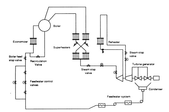
FIGURE 1. The power plant boiler.
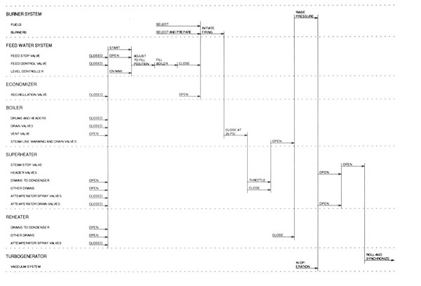
FIGURE 2. Generic start-up procedure for a power plant boiler.
Uncovering Plant Design Intentions in the Start-Up
The procedure shown in Figure 2 is only describing the temporal ordering of control actions, that is, the durations of the different actions are ignored. The temporal ordering is a reflection of logical constraints between the different parts of the start-up. In order to uncover the nature of these constraints we will take advantage of the information presented along the vertical axis where we have listed different physical subsystems in the plant, that is, the boiler, the feed water system, the burner system, the economizer, the superheater and the reheater, and the turbine generator. For each subsystem we have also listed the components that are objects of the actions in the different phases of the start-up. These components are therefore objects that can be manipulated and they are all valves (with a few exceptions). The ordering of the systems along the vertical axis is not arbitrary and is in fact crucial for our recognition of plant design intentions. The ordering makes visible the patterns of action which lead to the increase of functional integration of the power plant during the start-up. This functional integration is intended by the plant designer.
The functional levels established during start-up are not directly observable properties of plant components or subsystems. The functions are more abstract relational entities representing intended patterns of interactions between the plant parts. If these plant functions are known we can classify the different actions according to the purpose they serve in the start-up. Each action is ultimately a means of reaching the overall goal of producing electricity by the turbine generator. The function of each action toward this end must be found by describing how the action contributes to the management of the means of production in the plant, that is, it must be related to a classification of the different types of plant resource management tasks involved in the start-up.
A Classification of Plant Resource Management Tasks
The classification of plant resource management tasks can be obtained by representing the plant in a so-called abstraction hierarchy based on a means-end and whole part concepts. Lind (1990) describes a modeling technique called Multilevel Flow Modelling (MFM) which is based on these concepts. MFM makes a distinction between goals, functions, and the physical levels in the description of plant processes. The levels of functions and the physical components represent means which can be instrumental in the achievement of plant safety, production, and economy goals. By using such a representational framework we obtain the following general task categories:
• Configuration management. This comprises the following two subordinate task types:
Allocation of physical resources to functions. This is a planning task involving the choice between alternative physical implementations of a set of required plant functions. The task takes into account the interrelations between the physical and the functional levels. When several alternatives exist for the physical realization of plant functions, a planning agent must make a choice on the basis of the performance required and the capabilities of the different physical alternatives. The planning of system start-up and shut down and change over involves the consideration of this type of allocation task. The planning may be performed as part of the design of the plant processes or could be made dynamically by an operator or by a computer. Such a planning takes into account the conditions for availability of the physical resources. A plant component may be taken out of service for repair or maintenance and may in a dynamic planning situation force the planner to look for other alternatives.
Coordination of physical parts into functions. The purpose of this type of task is to coordinate the selected physical parts to perform selected plant functions considering operational constraints and control objectives.
• Management of plant functions. This comprises the following two subordinate task types:
Allocation of function resources to goals. This is a planning task which comprises the use of overall control strategies for choosing between alternative plant functions for the achievement of a selected goal. This task involves an evaluation of alternatives with respect to capability.
Coordination of functions into high level functions. This is a control task including the coordination of plant functions in order to realize a given goal. The control task is designed on the basis of the functional resources identified in the function allocation task. Goals for the coordination tasks are often based on optimization criteria.
The task categories defined above can be further subdivided into subordinate categories. These subordinate categories would however only be applicable within restricted domains. In the power plant example above we can with advantage distinguish between tasks related to the management of mass and energy. These types of tasks are of particular interest here because we will show later how the intentional structure of the power plant can be represented in terms of the Multilevel Flow Modelling technique (MFM).
The Start-Up Procedure Reconsidered
We can now resume our analysis of the start-up procedure for the power plant boiler. The distinctions introduced above between different categories of resource management tasks can now be used to reveal patterns of intentionality in the sequences of actions in the start-up. The result of such an interpretation is shown in Figure 3. It is seen from Figure 3 that the start-up actions can be aggregated into a set of subordinate tasks dealing with configuration management (CM), material (mass or energy) management (MM) and function support (FS). The actions being parts of these activities acquire their meaning when classified according to their functional value in task achievement. In order to realize this let us consider some examples.
The meaning of the action ‘close boiler feed control valve’ (‘stop feed water flow’ in Figure 2) is to be a means for the management of the mass balances involved in filling up the boiler with water. Furthermore the meaning of the action “open economizer recirculation valve” is to be a means for managing the physical configuration of the economizer circuit, with the purpose of protecting it from boiling dry. We thus see that even though these two actions are similar (by being manipulations of valves) they have different purposes.
These different purposes can be revealed by classifying the start-up activities into tasks as shown in Figure 3.
It is also seen from Figure 3 that as the procedure is progressing, the plant develops into a functionally integrated system. The last material handling task (MM3) involves all plant parts as the change of the state on any plant component in principle would have a consequence (small or large) for the achievement of the goal for this task (the production of electric energy). A manipulation of the economizer recirculation valve discussed earlier could in this phase have the purpose of optimizing the energy economy of the plant. It is seen that changing the state of the recirculation valve could in this context have a distinctly different purpose (if the state was intentionally changed).
These informal interpretations of the actions in the procedure are based on knowledge about the purposes of the different phases of the start-up. In the following we will show how this knowledge can be formalized and used in a more systematic way for understanding control actions.
MULTILEVEL FLOW MODEL OF THE POWER PLANT BOILER
In order to demonstrate that the analysis of the start-up procedure in Figure 4 can be related to levels of means-end and part-whole abstractions of the power plant boiler, we will in the following describe an MFM model of the boiler. It will be indicated how the different phases of the start-up relate to different parts of the model. We will furthermore illustrate how the MFM model can be used for plan synthesis.
The MFM model of the power plant boiler is shown in Figure 4, where also the meaning of the symbols used are depicted. As Lind (1990) provides a detailed introduction, we will not describe the principles of MFM modeling here. We will, however, in the following explain the details of the model. When reading the explanation, the reader is encouraged to consult Figure 1. showing the physical layout of the plant. First, we will define the meaning of the goals G0,…, G10 and explain how they relate to the flow structures structurel, structure2 and structure3. Second, we will describe the flow structures.

FIGURE 3. The start-up procedure with tasks indicated.
The Goals and the Related Flow Structures
The main goal of the power plant boiler is to provide an energy flow on the generator shaft. This goal is named GO in the model, and the means to achieve it are the flow functions represented by structure1. This energy flow structure describes the functions provided by the burner, boiler, turbines, and generator. Structure2 describes the mass flow functions involved in the fuel combustion process, and structure3 describes the mass flow functions provided by the boiler, turbine, condenser, and the economizer.
Structure2 supports three goals named G1, G2 and G3. They are all related to provide and transport the energy at the first stages of structure1, the top-level energy flow. G1 is the goal of providing a proper ratio between the air and fuel flows (to ensure combustion). G2 is the goal of having a flame and G3 expresses that a flow of combustion gases is needed to carry the heat into the economizer. Related to G2 is G9, which is the goal of having a chemical reaction between the fuel and the oxygen. This goal is achieved by structure1, specifically by means of the energy transport Tr1 that again is supported by the goal G2. The two goals G2 and G9 thus support each other. In physical terms this means that when a flame is first established, it is self-supporting. This circularity in the MFM model illustrates the fact that abstraction levels in an MFM model often combine into cyclic networks of goal and means (i.e., they are not structured as trees). Such cycles are the source of start-up problems. In the specific case considered, the flame is needed to ensure transport of energy in the boiler and this transport is a necessary means to maintain the combustion processes, that is, the flame. We therefore need to start the combustion process by another means, which indeed is the purpose of the ignition system (not included in the model).
Structure3 is used for achieving five goals G4, G5, G6, G7, and G8 that all support the transport of energy from the boiler to the turbine. G4 expresses the need to maintain a sufficient level of water in the boiler and G5 is the goal of having a steam flow from the boiler to the turbine. The energy conversion in the turbine only works properly if the vacuum system is operating, and thus G6 expresses the need to having the vacuum system in operation. Cooling is of course needed, too, and G7 is the goal of having the cooling water at a proper flow, while G8 is the goal of having a feed water flow. One of the functions of structure3 is also conditioned by a goal. The function is Tr14, the mass transport that is provided by the steam piping from the boiler to the turbine. This flow is conditioned by the goal G10, which expresses the need to maintain a pressure in the boiler. This goal is therefore achieved by structure1. This part of the model also comprises a cyclic component.
Description of the Flow Structures
Resources provided in the plant for goal achievement are represented by the flow functions in structure1, structure2, and structure3. Below we will, without going into too much detail, describe all the flow functions and explain their physical realization.

FIGURE 4. The MFM model of the power plant boiler.
Structure1 consists of the following functions: The source So1 is the energy source provided by the combustion of fuel and air. This energy is transported by the transport function Tr1 into the balance function B1. Tr1 is realized by (is a function of) the flame, and is hence conditioned by the goal G2. B1 models the balance between the incoming energy flow (Tr1) and the flow of energy into the water in the boiler (Tr2) and the energy flow carried away by the exhaust gases (Tr3). The balance B2 models the energy balance in the economizer, where the heat from the exhaust gases is used to pre-heat the feed water, which provides an energy transport function, modeled by Tr4. The heat eventually carried away from the economizer and “lost” in the chimney is modeled by Tr5. This energy is absorbed by the atmosphere that has the function of a sink, modeled by Si1. The energy transported by Tr2 ends up in the energy storage St1 provided by the water in the boiler. From this energy storage a flow is led by a transport function (Tr6) into a balance (B3) provided by the turbine. From B3 the energy is transported by two flows, one representing the work done on the generator shaft (Tr8) and one representing the residual heat in the steam on the low-pressure side of the turbine (Tr7). These flows end in two energy sink functions. Si2 models the energy sink provided by the generator and Si3 models the heat sink provided by the environment through sea water or the atmosphere.
The functions of structure2 representing the mass flow functions involved in the management of the fuel and air flows in the burner and fuel supply system. The source function So2 models the oil or coal inventory, which, despite its limited nature, plays the role of an infinite source in view of day-to-day operations. Likewise, the source function So3 models the source of air (oxygen) provided by the atmosphere. From these sources two transport functions lead to the mass balance function provided by the combustion process. The transport Tr9 models the function of the fuel pumps and pipes and Tr10 models the function of the air blowers and B4 models the combustion mass balance. Tr11 models the outflow of CO2 and Tr12 models the outflow of H2O. Only these two exhaust gases are modeled, since they are the basic ones. The sink functions modeled by Si4 and Si5 are both realized by the atmosphere.
Structures3 comprises the functions that are involved in the management of the flows of water and steam around the boiler and the condenser. St2 is the mass storage function that is provided by the boiler, B6 models the mass balance provided by the economizer and St3 models the mass storage function provided by the condenser. The transport functions between the two storage functions are Tr13, which models the feed water system between the economizer and the boiler, and Tr16, which models the feed water system between the condenser and the economizer. Tr14 models the mass (steam) transport provided by the high-pressure steam piping, the re-heaters, the turbines and the vacuum system. Tr19 is transport into the condenser of feed water and So5 is its source. The network So4-Tr17-B7-Tr18-Si6 comprises the functions of the cooling water side of the condenser. The source (So4) and the sink (Si6) are both functions of the sea water or water in a cooling tower and the balance B7 is provided by the cold side of the condenser. The transports Tr17 and Tr18 are realized by the cooling water pumps and pipes. The barrier function Barrier1 is provided by the pipes in the heat exchanger of the condenser and has the purpose of separating the possibly polluted cooling water from the feed water involved in the energy production processes.
Using the Model For Planning Purposes
When the model thus developed is to be used for planning, the quite general nature of the knowledge discussed earlier needs some specialization. To provide deeper knowledge about the workings of the plant, more conditions must be associated with the functions of the model. In this paper, where the focus is on start-ups, the conditions are divided into three categories. It is possible that another focus (for instance on diagnosis) would require different categories. The three categories of condition used in this paper deal with the following aspects of a function:
• The structural support
• The materials being treated
• Fitness of the function to other functions
The structural support is either provided by equipment of the plant or by a lower level function that provide the means. In an MFM model this last possibility corresponds to functions that are not conditioned on a goal, and those that are, respectively.
The existence of a structural support ensures the basic behavior of the function, but the problem is that functions only exist in the context of the operation of the plant. This means that a function needs other functions surrounding it to provide the context, that is, the environment in which it makes sense to talk about it as a function.
Hence, the environment must on one hand provide the material (water or heat, for instance) that the function must treat. On the other hand it also induces limits on the states of the components themselves or the operation of them to ensure that the behavior is useful for the group of functions as a whole. The useful behavior is here considered to be the behavior of the function ensuring that other functions can cooperate with it, that is, where it fits them. Examples of this could be a minimum flow in a transport function or a minimum level in a storage function.
Fulfilling the material condition is done by the surrounding functions that then have the function of delivering material to the function in question. The fitness condition, on the other hand, must be met by tuning the state of the plant to ensure that the levels and the flows have correct values.
The conditions on the functions may therefore be expressed as states of the equipment or the process. A state of the equipment may be that a valve is open or closed, that a pump is turned on or that an entire sub system is in operation if it can be regarded as one unit. The state of the process is expressed in terms of pressure, temperature, concentration and so on for the materials being treated by the plant, and largely determines the fitness condition of the functions. It may for some functions be controlled directly, for instance by means of a pump or a control valve. These functions are active, whereas others, for which the behavior is determined by the operating of the surrounding systems or the plant in general, are passive functions.
As there is more than one condition for many functions, there is also the possibility that a function is only partly established if only some of the conditions are fulfilled. Some of these states may be meaningful, and as we concentrate on start-ups, we will focus on the intermediate steps before a function gets established. In this analysis only two main steps are recognized – the intermediate and the final. After the intermediate step a function is said to be enabled and after the final step it is said to be established.
An enabled function is a function that is ready to be integrated with the other functions, but it is not yet necessarily working, in the sense that it processes material. It thus means that it might be ready to receive a material, for instance. An example of this could be the boiler that is enabled as an energy storage when there is water in it, since it would be able to receive heat from the flame in a proper way. For a function to be established — the next step — the systems realizing it must be working as they are intended to, meaning that the material they are expected to process will be processed properly.
An established function is hence integrated with at least a necessary minimal number of surrounding functions, by which is referred to the functions that must be established (or enabled) around it for it to work.
INTERPRETATION OF THE START-UP PROCEDURE
We can now relate the MFM model in Figure 4 with the classification of tasks in the start-up procedure shown in Figure 3. Due to the relations between the flow structures given by the condition and achieve relations and the auxiliary conditions introduced above, we can directly recognize the overall structure of the procedure from the MFM model in Figure 4.
On a general level, we can see that functions of structure2 and structure3 must be established before the functions in structura1. Furthermore, the goals achieved by functions in structure2 and structure3 must be achieved before functions in structurel are established. What we read directly from the overall structure of the MFM model corresponds in the procedure to the precedence of the tasks CM3, CM4, and MM1 to CM5 and MM2 and of the task CM6 to MM3.
The task MM1 corresponds to filing up the boiler with water. The associated plant resources and their interrelations are represented by the functions of structure3. The tasks CM3 and CM4 comprise the configuration of the fuel and burner system. The associated plant resources and their interrelations are represented by structure2. The task CM5 corresponds to a configuration of the energy flow, since a flow of energy into the boiler is established. The tasks MM2 and MM3 comprise the management of the heating up of the feed water, the production of steam and the conversion of steam energy to electricity in the turbine generator. These two tasks are separated by the task CM6, which comprises the configuration of the steam flow from the boiler to the turbines. MM2 and MM3 are both related to the plant resources in structure1, while CM6 is related to the plant resources in structure3, although this task has immediate consequences on the configuration of the energy flow, that is, the plant resources of structure1.
The function support tasks are less evident, but comprise configuration of the plant to ensure that the plant functions are also maintained when the operating point is changing. The task FS 1 configures the equipment around the economizer to ensure that the water is kept at a satisfactory level all during the startup, ensuring that the proper mass balances are maintained. The purpose is to ensure that the economizer does not boil dry during the start-up, and hence to ensure the integrity of the equipment of the plant. The tasks FS2, FS3, and FS4 comprise configuring the equipment around the boiler and the steamline to maintain the ability of the boiler to receive the energy received from the burners, also at higher pressures and temperatures. The task FS5 comprises the configuration of the equipment around the low pressure turbine to ensure that the relation between the energy flows is satisfactory. The task FS6 comprises the configuration of the equipment around the superheater to ensure that it is able to handle the temperature of the steam.
Tying the Tasks to the Functions
Having identified both the nature of the tasks, as discussed above, and the functions of the plant as using the MFM model, the two analyses can be combined.
The Configuration Management tasks all correspond to tasks that more or less directly lead to a function being established. Using the terminology from above, most of these tasks establish the structural support for the function, which in turn leads to the establishment of the function.
Based on this principle, the Configuration Management tasks may be seen as establishing the following functions:
• CM1 enables the water storage function of the boiler, that is, St2 in the model.
• CM2 establishes the water transport function of the feed water system, that is, Tr16.
• CM3 establishes the fuel source function, that is, So2.
• CM4 enables the mass transport function of the burners, that is, Tr9.
• CM5 establishes the mass (fuel) and energy transport function corresponding to the burners, that is, Tr1.
• CM6 establishes the mass transport function from the boiler to the high pressure turbine, that is, Tr6.
All the functions being established above need other conditions to be fulfilled also, for instance, the task CM2 has as a pre condition that there is water present in the hotwell of the condenser.
The material handling tasks correspond to control tasks that serve to meet the fitness requirement for the function involved.
• MM1 ensures a level of water in the boiler that serves to fully establish the mass storage function of the boiler, that is, St2.
• MM2 is used for achieving the correct pressure in the boiler, hence establishing the boiler’s energy storage function, that is, St1.
• MM3 brings the level of energy stored in the turbine generator to the prescribed level, thus ensuring that the energy balance function B3 is interacting correctly with the surrounding functions.
Two types of the Function Support tasks exist. One is the type of task that serves to ensure that the integrity of the equipment is kept, so that, for instance, material temperatures are not exceeded. The tasks of this kind are:
• FS3, which ensures that the steam line material is not exposed to excessive temperature gradients, that is, it ensures that the mass transport function Tr6 will be available also at higher temperatures.
The following tasks have the purpose of keeping a function enabled also when the operating conditions are changed:
• FS1, which ensures that the economizer does not boil dry, that is, that the mass balance function of the economizer (B6) is enabled also when the boiler is fired.
• FS2 and FS4 ensure that the boiler is able to receive energy also at higher pressures, which means that it keeps the energy storage function of the boiler (St1) enabled while the pressure is raised.
The task FS5 serves to ensure a proper distribution of the energy across the turbine, hence supporting the function of the turbine as an energy balance (B3).
The task FS6 serves to ensure the proper function of the superheater, both as a mass and as an energy transport function by removing excessive water. This is thus not a task that in itself establishes the function, but it is needed to ensure that the function is existing also at higher production rates.
It is important to emphasize that the procedure in Figure 2 (and Figure 3) and the MFM model are not equivalent representations of the power plant boiler. Actually, the MFM model represents plant control tasks, their interrelations, and the resources provided by the plant designer for their achievement. The MFM model is therefore not a plan representation but a basis for the synthesis of a plan and the procedure analyzed above comprises therefore only one set of actions out of many possible accomplishing the same purpose. MFM models can also be used for interpretation of plant states, that is, for diagnosis. The diagnostic aspects of MFM are described by Lind (1991).
THE USE OF MULTILEVEL FLOW MODELLING FOR PLANNING
MFM models represent only the plant goal-function structures, and rules of interpretation or reasoning about the model are therefore required in order to generate a plan. Below, we will describe how MFM models can be used for the synthesis of plans. The rules used for planning will actually reveal further intentional knowledge about the plant because they will express strategies for plant resource management.
The problem of synthesizing control task structures is basically a planning problem involving the composition of a sequence of actions that will lead to the system defined goal state. However, when modeling the plant in terms of MFM, we formulate the planning problem as being a problem of matching the goal to be achieved with the available plant means or resources. Accordingly, instead of formulating the planning problem in terms of actions on the plant we instead phrase it in terms of the plant resources available for control.
As MFM models describe goals and functions on different levels of abstraction, the generated plans will be composed of sequences of abstract actions (intentions). The intentions can be considered as goals as they cannot be directly implemented in terms of physically executable actions. A plan synthesized on the basis of an MFM model will accordingly represent a decomposition of an overall goal into a sequence of subgoals (abstract actions). Intentions can be implemented into physical actions if the plant control interface allows the operator to express abstract goals as commands (e.g., “establish mass transport TrXX”).
When synthesizing a plan there will usually be many feasible solutions. To select a plan for execution it is accordingly necessary to use heuristics that express rules to follow based on experience. An important part of this knowledge is included in an MFM model in terms of the conditions which relate the different functional levels in the model. Conditions for existence of plant functions will always relate to operational constraints, that is, the conditions cannot be derived from the principles of physics but express conditions for proper function. This important difference between natural constraints and rules of rightness is discussed by Polyani (1962).
The conditions in MFM models represent heuristic information about operational experience. For start-up purposes the relevant operational experience is knowledge about what the sufficient conditions are for each function to exist. These conditions are expressed mainly by the MFM goals. And, as each goal may be achieved by one or more structures, meeting the goal induces the need of ensuring that the necessary functions of the underlying structure exist. The knowledge we can extract from this ‘vertical’ dimension of the MFM model is thus which lower level functions are needed to perform a desired (sub) task of establishing a function at a higher level. The functions at the lowest levels are not related to MFM goals but to the plant equipment and the process, in which case the knowledge that we can extract is which parts of the equipment to operate.
CONSTRUCTION OF THE TASK DESCRIPTIONS
Using the knowledge from the MFM models one can produce task descriptions that tell how to establish a function in the plant. The primary contents of these task descriptions are subgoals that correspond to the conditions of the three categories mentioned above.
The task descriptions are divided into two categories, reflecting that establishing a function is a task that must be done in several steps, and that for each step the functions get “more and more established.” There are two types of tasks for the establishment of a function, corresponding to the two steps on the way to establishment of a function: enablement and establishment. The first is the enablement task and the other is the establishment task. The latter has the result of the former as a precondition. Further, there are also task descriptions for the achievement of an MFM goal.
The task descriptions consist of a list of subgoals consisting mainly of the three conditions (structural, material, and fitness) mentioned earlier. In the task descriptions mentioned below, three additional types will be used:
• enablement precondition. This is a type of precondition that is used for function establishment tasks to ensure that a function is enabled before it is established.
• execution condition. This is a type of condition that must be fulfilled all through the execution of the task. For a discussion of this, see (Hollnagel, 1993).
• achievement subgoal. This is a subgoal describing how an MFM goal element is achieved.
Examples of Task Descriptions
As an example of how the task descriptions are used in practice, the operation of the boiler can be used. The example will walk through the actions and the functions needed to fill the boiler with water, reach the boiling point and the pressure raised to a sufficient level. Some of the subgoals concerning purely passive functions are simplified to keep the example small. This is indicated for the subgoals in question. The task descriptions are listed in Table 1.
To achieve a goal of establishing the energy storage of the boiler, it must first be translated into the goal “St1 established.” Using the task description above, this goal can be divided into three subgoals, “St1 enabled,” “Heat from burner,” and “Pressure within specified limits.” These subgoals must be met in this order. Furthermore, the task leads to a subtask to ensure that St1 is kept enabled constantly.
The subgoal “St1 enabled” may be achieved by performing the subtask number two in the list above, which has itself only one subgoal, that G4 is achieved. To achieve G4, St2 must be established. This again gives rise to three subgoals. The first is that it is enabled. The second is that there is water to fill the boiler, and the third is that the level of water in the boiler is correct.
To enable the storage function, the last task mentioned above may be used, leading to the subgoal that the drain valves are closed. The subgoal of having feed water present to fill the boiler involves that Tr13, B6, and Tr16 must be established, leading to the demands that
1) the economizer recirculation valve be opened, as this is needed to establish B6, and
2) the feed water system be started, as this will establish Tr16.
The task descriptions of the example

Once the feed water is available to the operator, the prescribed level of water in the boiler must be achieved. This task will fulfill the fitness condition of the mass storage function of the boiler, thus achieving the goal G4 and in turn also enabling the energy storage function of the water in the boiler. To establish this function, the heat transport must be established, which means that the burner system must be prepared and fired. As the last subtask of establishing the energy storage function of the boiler, the pressure must reach a prescribed value.
In Figure 5, the tasks are shown graphically, with labels showing the tasks from the chart in Figure 3 that may be used to establish a specific state. One label is “Always,” as this is a state that can be considered to be reached at all times. The expansion of the task of providing heat from the burners is shown, and some intermediate functions are skipped in the branch of the task to provide feed water to the boiler.

FIGURE 5. The goal structure as expanded by the task descriptions.
Interpretation of the Task Structure
The task structure has two interpretations. One is to specify a plan that will bring the system into the desired goal state. For this purpose the bottom level nodes of the structure provide a series of actions and if read from left to right, the order will comply with the requirements of the functions of the plant. Hence, from this little example it can be seen that the task CM1 must be carried out before CM2, which again must be carried out before MM1. This way to use the structure gives a simple plan in the form of a linear sequence of actions and the structure can accordingly serve as a basis for planning support of operators.
The other interpretation is to use the structure for understanding a sequence of actions by propagating information about actions carried out from the bottom upwards. In this way the immediate consequences of the actions can be seen, as well as the goals that may be achieved later on following the execution of the action. This interpretation will, however, be based on the knowledge that the overall context is a start-up. As an example of this, it may be seen that closing the boiler drain valves, in the context of a start-up, has the purpose of enabling the boiler as a mass (water) storage, which later will enable the energy storage. As all the tasks exist in the context of a start-up, the ultimate state that any action can lead to is that the plant is operating. Hence, it is the states in between the action and the final state that are interesting in this case. This interpretation of the task structure can be a basis for supervising the operator’s actions.
PLANNING SUPPORT IN DYNAMIC ENVIRONMENTS
The discussions in the previous sections have demonstrated the relevance of plant design intentions for the planning of actions and for their interpretation. We have also shown that the MFM modeling technique can provide a basis for a formalized representation of design intentions and, by means of an example, that an MFM model can be used for the generation of plans. With this as a basis we will now address the human-machine interface design issues left unresolved in the beginning of the chapter.
We argued that agents acting in artificial environments necessarily would have knowledge about the design intentions in order to be adapted to the environment. However, in the analysis we did not make any assumptions about the nature of the interface between the agent and his environment. In other words, the adaptation was a feature of the total system agent-environment. From an overall systems design perspective, the required adaptation of the agent to the environment (and also the other way around for that matter) becomes a requirement to the design of the interface. But the complexity of the environment and the complexity of the planning task constrains the kinds of environment the agent can cope with without computer based support. The discussion of the planning task above and the MFM modeling demonstrates a representational problem. We will characterize this problem in some detail below.
The Problem of Representation
There is a representational problem because the agent is not able by direct inspection of the environment to infer the intentions of the plant designer from knowledge about the physical properties of the plant. This inference requires background knowledge about the functional requirements of the plant and about the designers’ strategies. This means that it is difficult for the agent unaided to acquire the knowledge of the environment which is required to perform his tasks. This representational problem has a parallel in the understanding of natural language, where a representation of the underlying semantics of the situation is required in order to resolve ambiguities in the interpretation. Actually Schank’s Conceptual Dependency for representation of natural language semantics (Schank & Abelson, 1977) is similar to MFM models, which represent semantic aspects of the artificial environment. Schank’s work and the related work of Wilensky (1983) are discussed in Hoc, 1988, in relation to more general planning problems.
It should be noted that MFM models can be complex representations, even for systems which on the surface seem simple enough (see, e.g., the MFM model of a central heating system discussed in Lind (1990)). The semantics of the artificial environments will, in our experience with MFM modeling, turn out to be complex in most realistic cases. Their MFM representations will include several or many levels of abstraction and cyclic means-end structures.
Concluding Remarks
With this analysis of the planning tasks in artificial environments we may conclude that there is a need for computer based support in order to handle the representational problem.
We have not discussed how human operators actually perform in planning tasks. However, the findings of Suchman (1987) indicate that humans are very bad, or at least not optimal, planners. But supervisors interacting with an environment that has a complex intentional structure, a feature of most industrial plants, need to plan in order to stay tuned with the task environment. If Suchman’s findings are correct, we therefore can conclude that supervisors interacting with such environments would need computer support, and that this support should reveal the intentional structure of the environment. There seems also to be scope for a human-computer cooperation, where the role of the computer is to resolve the complexity of the artificial environment, and where the operator is able to implement his own objectives and plans, as long as they are within the envelope of plant design intentions. Such a cooperation would require a combined use of the two interpretations of the task structures as described by Lind (1993) and Larsen (1993). The system would in this way take advantage of both the operator’s expertise, that is his own strategies, and the knowledge and expertise of the plant designer.
REFERENCES
Hoc, J.M., (1988). Cognitive Psychology of Planning. London: Academic Press.
Hollnagel, E., (1993). Human reliability analysis: Context and control. London: Academic Press,.
Larsen, M. N. (1993) Modelling start-up tasks using functional models (Tech. Rep. No. 4937-92-08-ED ISP DK). Lyngby, Denmark: Technical University of Denmark..
Lind, M., (1990). Representing goals and functions of complex systems (Tech. Rep. No 90-D- 381). Lyngby, Denmark: Technical University of Denmark.
Lind, M., (1991, September). On the modelling of diagnostic tasks. Paper presented at the Third Cognitive Science Approaches to Process Control conference, Cardiff, UK.
Lind, M. (1993). Interactive planning for integrated supervision and control in complex plant (Tech. Rep. No. 4937-92-08-ED ISP DK). Ispra, Italy: CEC Joint Research Centre.
Polyani, M., (1962). Personal knowledge. London: Routledge & Kegan Paul.
Schank, R. & Abelson, R. (1977). Scripts, plans, goals, and understanding. Hillsdale, NJ: Lawrence Earlbaum Associates.
Simon, H.A. (1981). The sciences of the artificial. Cambridge, MA: MIT press.
Suchman, L.A. (1987). Plans and situated actions. Cambridge, UK: Cambridge University Press.
West, K.L. (1972, December). Minimum recommended protection, interlocking and control for fossil fuel unit-connected steam station. Paper presented at the IEEE Winter Power Group Meeting, New York.
Wilensky, R. (1983). Planning and understanding. London: Addison Wesley.