Chapter 2
Principles of Fiber-Optic Transmission
The following ETA Fiber-Optics Installer competencies are covered in this chapter:
 Describe the basic parts of a fiber-optic link.
- Describe the basic operation of a fiber-optic transmitter.
- Describe the basic operation of a fiber-optic receiver.
- Explain how to express gain or loss using the decibel (dB).
- Explain how to express optical power in dBm.
Like Bell's photophone, the purpose of fiber optics is to convert a signal to light, move the light over a distance, and then reconstruct the original signal from the light. The equipment used to do this job has to overcome all of the same problems that Bell encountered, while carrying more data over a much greater distance.
In this chapter, you will learn about the basic components that transmit, receive, and carry the optical signal. You will also learn to
- Calculate the decibel value of a gain or loss in power
- Calculate the gain or loss in power from a known decibel value
- Calculate the gain or loss in power using the dB rules of thumb
- Convert dBm to a power measurement
- Convert a power measurement to dBm
The Fiber-Optic Link
A link is a transmission pathway between two points using some kind of generic cable. The pathway includes a means to couple the signal to the cable and a way to receive it at the other end in a useful way.
Any time we send a signal from one point to another over a wire, we are using a link. A simple intercom, for example, consists of the sending station (which converts voice into electrical signals), the wire over which the signals are transmitted, and the receiving station (which converts the electrical signal back into voice).
Links are often described in terms of their ability to send and receive signals as part of a communication system. When described in these terms, they are broken down into simplex and duplex. Simplex means that the link can only send at one end and receive at the other end. In other words, the signal goes only one way. An example is the signal from a radio station. Duplex means that the link has a transmitter and a receiver at each end. A half-duplex system allows signals to go only one way at a time—an example is an intercom system. A full-duplex system allows users to send and receive at the same time. A telephone is a common example of a full-duplex system.
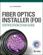
A fiber-optic link, shown in Figure 2.1, is like any other link, except that it uses optical fiber instead of wire. A fiber-optic link consists of four basic components:
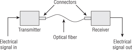
Figure 2.1 The fiber-optic link
- The transmitter that converts a signal into light and sends the light
- The receiver that captures the light and converts it back to a signal
- The optical fiber that carries the light
- The connectors that couple the optical fiber to the transmitter and receiver
Now let's look at each component in a little more detail.
Transmitter
The transmitter, shown in Figure 2.2, converts an electrical signal into light energy to be carried through the optical fiber. The signal can be generated by many sources, such as a computer, a voice over a telephone, or data from an industrial sensor.

Figure 2.2 The fiber-optic transmitter
Receiver
The receiver is an electronic device that collects light energy from the optical fiber and converts it into electrical energy, which can then be converted into its original form, as shown in Figure 2.3. The receiver typically consists of a photodiode to convert the received light into electricity and circuitry to amplify and process the signal.

Figure 2.3 The fiber-optic receiver
Optical Fibers
Optical fibers carry light energy from the transmitter to the receiver. An optical fiber may be made of glass or plastic, depending on the requirements of the job that it will perform. The advantage of light transmission through optical fiber as compared to the transmission of light through air is that the fiber can carry light around corners and over great distances.
Many fibers used in a fiber-optic link have a core between 8 and 62.5 microns (millionths of a meter) in diameter. For comparison, a typical human hair is about 100 microns in diameter. The cladding that surrounds the core is typically 125 microns in diameter.
The optical fiber's coating protects the cladding from abrasion. The thickness of the coating is typically half the diameter of the cladding, which increases the overall size of the optical fiber to 250 microns. Even with the additional thickness of the coating, optical fiber cabling is much smaller and lighter than copper cabling, as shown in Figure 2.4, and can carry many times the information.

Figure 2.4 Comparison of copper cable (top) and fiber cable (bottom)
Connectors
The connector is attached to the optical fiber and the fiber-optic cable. The connector allows the optical fiber to be mated to the transmitter or receiver. Transmitters or receivers typically have a receptacle that securely holds the connector and provides solid contact between the optical fiber and the optical subassembly of the device. The connector must align the fiber end precisely with the light source or photodiode to minimize signal loss.
The connectors, shown in Figure 2.5, could be considered the elements that make it possible for us to use fiber optics because they allow large hands to handle the small, fragile fibers. They are also the only place in the link where the optical fiber is exposed.
Figure 2.5 Fiber-optic connectors
Decibels (dB)
As light travels away from its source through the link, it loses energy. Energy loss can be caused by several factors, such as the absorption or scattering of light by impurities in the fiber, or by light passing through the core and cladding and being absorbed in the coating.
It is important to be able to measure the amount of light energy lost in a fiber-optic link. Knowing the loss allows us to predict the strength of the light energy at the receiving equipment. The receiving equipment needs a minimum amount of light energy to accurately convert the light energy to the original signal. In addition, an understanding of how and where light is lost in a link can be helpful when troubleshooting the link.
One of the more common terms used when discussing the quality of a signal in fiber optics is the decibel (dB). The decibel was originally used to measure the strength of sounds as perceived by the human ear. Its name means “one-tenth of a bel.”
Calculating dB Power Loss and Power Gain
The decibel can be used to express power gain or power loss relative to a known value. In fiber optics, the decibel is most commonly used to describe optical power, which is also known as signal power. Optical power is typically measured with an optical power meter (OPM). Measuring optical power with an OPM is covered in detail in Chapter 14, “Test Equipment and Link/Cable Testing.”
Recall that in the 1960s, a signal loss of 20 decibels per kilometer was considered the goal for making fiber optics practical for communications. A 20-decibel loss means that of the original power put into the signal, only 1 percent remains.
Modern optical fiber has very low signal power loss and many fiber-optic links do not require the signal to be amplified. The decibel is used to express the signal power loss in all fiber-optic links. In links that extend many kilometers, it is used to express the signal power gain provided by the amplifier.
To calculate the decibel value of a gain or loss in optical power, use the following equation:
- dB = 10Log10 (Pout ÷ Pin)
Let's apply this equation to the loss associated with a length of optical fiber. The transmitter couples 10 microwatts (μW) into the optical fiber and the power at the receiver is 3μW. Since both values are in microwatts, we do not have to use microwatts in the equation. The equation would be written as follows:
- dB = 10Log10 (3 ÷ 10)
- dB = 10Log10 0.3
- dB = –5.23
- Loss = 5.23dB
Because the calculated value is negative, it is a loss. When a loss is stated, the negative sign is dropped. The loss is 5.23dB.
Most fiber-optic applications do not require amplification. However, amplification may be required for long transmission distances. If the input power and output power of the amplifier are known, the gain in dB can be calculated. We can solve for the gain of an amplifier where the input power is 1μW and the output power is 23μW by solving the equation as shown here:
- dB = 10Log10 (23 ÷ 1)
- dB = 10Log10 23
- dB = 13.6
- Gain = 13.6dB
If you know the decibel value and want to calculate the gain or loss, you will have to rearrange the equation as shown here:
- (Pout ÷ Pin) = antilog (dB ÷ 10)
Let's apply this equation to the loss associated with a length of optical fiber. To solve for the gain or loss we do not need to know the input power or output power; we just need the gain or loss in dB. Remember the loss in dB is a ratio of power out divided by power in. This length of optical fiber has a loss of 3.5dB. The equation would be written as follows:
- (Pout ÷ Pin) = antilog (dB ÷ 10)
- (Pout ÷ Pin) = antilog (–3.5 ÷ 10)
- (Pout ÷ Pin) = antilog –0.35
- (Pout ÷ Pin) = 0.447
If one power is known, the other power can be calculated. In this example, the input power is 13 milliwatt. To calculate the output power the equation would be written as follows:
- (Pout ÷ 13mW) = 0.447
- Pout = 0.447 × 13mW
- Pout = 5.8mW
Signals may be decreased, or attenuated, just about anywhere in the link. In addition to attenuation in the optical fiber itself, connectors, splices, and bends in the fiber-optic cable can also cause loss in the signal—sometimes considerable loss.
Expressing dB in Percentages
When measuring signal power gain or loss, decibels are calculated relative to the original power, rather than as an absolute number. For example, a loss of 0.1 decibel means that the signal has 97.7 percent of its power remaining, and a loss of 3 decibels means that only 50 percent of the original power remains. This relationship is logarithmic, rather than linear, meaning that with each 10 decibels of loss, the power is 10 percent of what it was (as shown in Table 2.1).
Table 2.1 Decibel losses expressed in percentages
| Loss in dB | % power lost | % power remaining |
| 0.1 | 2.3% | 97.7% |
| 0.2 | 4.5% | 95.5% |
| 0.3 | 6.7% | 93.3% |
| 0.4 | 8.8% | 91.2% |
| 0.5 | 10.9% | 89.1% |
| 0.6 | 12.9% | 87.1% |
| 0.75 | 15.9% | 84.1% |
| 0.8 | 16.8% | 83.2% |
| 0.9 | 18.7% | 81.3% |
| 1 | 21% | 79% |
| 3 | 50% | 50% |
| 6 | 75% | 25% |
| 7 | 80% | 20% |
| 9 | 87% | 13% |
| 10 | 90% | 10% |
| 13 | 95.0% | 5% |
| 16 | 97% | 3% |
| 17 | 98.0% | 2.0% |
| 19 | 98.7% | 1.3% |
| 20 | 99.00% | 1.00% |
| 23 | 99.50% | 0.50% |
| 30 | 99.9% | 0.1% |
| 33 | 99.95% | 0.05% |
| 40 | 99.99% | 0.01% |
| 50 | 99.999% | 0.001% |
| 60 | 99.9999% | 0.0001% |
| 70 | 99.99999% | 0.00001% |
With each 10 decibels of gain, the power is 10 times what it was (as shown in Table 2.2).
Table 2.2 Decibel gains expressed in percentages
| Gain in dB | % power increase | % total power |
| 0.1 | 2.3% | 102.3% |
| 0.2 | 4.7% | 104.7% |
| 0.3 | 7.2% | 107.2% |
| 0.4 | 9.6% | 109.6% |
| 0.5 | 12.2% | 112.2% |
| 0.6 | 14.8% | 114.8% |
| 0.75 | 18.9% | 118.9% |
| 0.8 | 20.2% | 120.2% |
| 0.9 | 23.0% | 123.0% |
| 1 | 26% | 126% |
| 3 | 100% | 200% |
| 6 | 298% | 398% |
| 7 | 401% | 501% |
| 9 | 694% | 794% |
| 10 | 900% | 1,000% |
| 13 | 1,895% | 1,995% |
| 16 | 3,881% | 3,981% |
| 17 | 4,912% | 5,012% |
| 19 | 7,843% | 7,943% |
| 20 | 9,900% | 10,000% |
| 23 | 19,853% | 19,953% |
| 30 | 99,900% | 100,000% |
| 33 | 199,426% | 199,526% |
| 40 | 999,900% | 1,000,000% |
| 50 | 9,999,900% | 10,000,000% |
| 60 | 99,999,900% | 100,000,000% |
| 70 | 999,999,900% | 1,000,000,000% |
One of the advantages of using decibels when calculating gain and loss is their relative ease of use compared to percentages. When measuring loss through different components, you can algebraically add the decibel loss from each component and arrive at a total signal loss for the system. If you were to use percentages, you would have to calculate the remaining power after the signal passed through each component, then take another percentage off for the next component, and so on, until the loss through the entire system had been calculated.
The Rules of Thumb
When calculating gain or loss in a system, it is useful to remember the three rules of thumb shown in Table 2.3, which make it easier to perform some common decibel calculations. These rules help you calculate how much power you have after the indicated decibel gain or loss.
Table 2.3 Rules of thumb
| Decibel | Loss | Gain |
| 3dB | 1/2 | × 2 |
| 7dB | 4/5 | × 5 |
| 10dB | 9/10 | × 10 |
For example, a loss of 3 decibels means that you have about 1/2 of the original power. A gain of 3 decibels means that you have about twice the original power. These rules are intended for rough calculations only, because a 3 decibel loss actually leaves 50.1187 percent of the original power, and a 7 decibel loss leaves 19.953 percent of the original power.
Because decibels can be algebraically added and subtracted, you can use combinations of the decibel values to determine total gains or losses. For example, the rules of thumb can be applied to find the power output from an amplifier with an input of 10μW and a gain of 17dB. First, apply the 10dB rule and multiply 10μW by 10. Then apply the 7dB rule and multiply. the result of the first calculation by 5. That value is the power remaining as shown in the following equations:
- Pout = 10μW × 10
- Pout = 100μW
- Pout = 100μW × 5
- Pout = 500μW
- The optical power at the output to the amplifier is 500μW.
Keep in mind that the dB rules of thumb cannot calculate the answer for every scenario. If the gain for the amplifier had been 18dB, we would not have been able to accurately calculate the optical power output of the amplifier. However, we would have been able to estimate that value by calculating for the closest value possible 17dB. The estimated output would be greater than 500μW but less than 1mW. The 1mW value is the result of solving the above equation a gain of 20dB, the closest value above 18dB that can be calculated using the dB rules of thumb.
Absolute Power
Taken by itself, the decibel is only a relative number, and it has meaning only when it is referenced to a known input or output power. In many cases, however, it is important to have an absolute value to use for comparison or for equipment specifications. When such a value is required in fiber optics, the decibel is referenced to 1mW. When the decibel is referenced to 1mW, a lowercase “m” or sometimes “mW” is inserted after dB. The decibel (dB) referenced to 1mW is written as 0dBm.
aWhen using dBm, power levels below 1mW are negative and power levels 1mW or greater are positive. The positive sign is typically implied and only the negative sign is used. As an example, value of –10dBm means that 1mW of power has been attenuated by 10dB, so only 10 percent of its power, or 100μW, remains. A value of 10dBm means that 1mW of power has been increased by 10dB, which has a value of 10mW. Table 2.4 shows how dBm values convert to power measurements.
Table 2.4 Converting power to dBm
| Optical power in watts | Optical power in dBm |
| 100mW | 20dBm |
| 20mW | 13dBm |
| 10mW | 10dBm |
| 8mW | 9dBm |
| 5mW | 7dBm |
| 4mW | 6dBm |
| 2mW | 3dBm |
| 1mW | 0dBm |
| 500μW | –3dBm |
| 250μW | –6dBm |
| 200μW | –7dBm |
| 125μW | –9dBm |
| 100μW | –10dBm |
| 50μW | –13dBm |
| 25μW | –16dBm |
| 20μW | –17dBm |
| 12.5μW | –19dBm |
| 10μW | –20dBm |
| 5μW | –23dBm |
| 1μW | –30dBm |
| 500nW | –33dBm |
The formula used to convert dBm to a power measurement is:
- dBm = 10Log10 (P ÷ 1mW)
This equation is similar to the equation for finding a decibel value from an input power and an output power, except that in this case the input power is fixed at 1mW. Let's apply this equation to calculate optical power from a dBm value. In this example the power meter measures –11dBm. To calculate the power in watts, the equation would be written as follows:
- –11 = 10Log10 (P ÷ 1mW)
- –1.1 = Log10 (P ÷ 1mW)
- 0.0794 = P ÷ 1mW
- P = 0.0794 × 1mW
- P = 0.0794mW
We can also convert a power measurement into dBm. Remember that when using dBm, power levels below 1mW are negative and power levels 1mW or greater are positive. The formula used to convert a power measurement to dBm:
- dBm = 10Log10 (P ÷ 1mW)
Let's apply this equation to calculate dBm from an optical power value of 10μW. To calculate dBm from the power in watts, the equation would be written as follows:
- dBm = 10Log10 (10μW ÷ 1mW)
- dBm = 10Log10 (0.01)
- dBm = 10 × –2
- dBm = –20
- The power value is –20dBm.
This answer can be checked by locating 10μW in the first column of Table 2.4.
Summary
This chapter discussed the basic components that transmit, receive, and carry the optical signal. It introduced the decibel and described how it is used to express power gain or power loss relative to a known value. In addition, it explained absolute power when the decibel is referenced to 1mW.
Exam Essentials
- Know the components of the fiber-optic link. Make sure you understand the four components that make up any fiber optic link. Also, you should know the function of each component within the link.
- Understand the importance of decibels (dB). Know why it is important to measure energy loss through a fiber optic link. Make sure you understand how decibels relate to the percentage of power gained or lost from the original signal.
- Know the difference between relative power and absolute power. Know that taken by itself, the decibel is only a relative number, and it has meaning only when it is referenced to a known value. Understand that when the decibel is referenced to 1mW it is written as 0dBm and can be used to describe an absolute power value.
Review Questions
- Which of the following groups describes the components in a fiber-optic link?
A. Transmitter, receiver, optical fiber, decoder
B. Transmitter, receiver, optical fiber, connectors
C. Transmitter, receiver, optical fiber
D. Transmitter, receiver, optical fiber, cabling
Hint: Send signal, carry signal, capture signal
- In a fiber-optic link, which component has an input of electrical energy and an output of light?
A. Connector
B. Optical fiber
C. Receiver
D. Transmitter
Hint: It sends the signal.
- If an optical signal loses 10dB, what percentage of the original signal is remaining?
A. 90%
B. 80%
C. 50%
D. 10%
Hint: It could be calculated using the rules of thumb.
- In a fiber-optic link, which component has an output of electrical energy and an input of light?
A. Connector
B. Optical fiber
C. Receiver
D. Transmitter
Hint: It captures the light.
- If the output power of a transmitter is 100μW and the power measured at the input to the receiver is 12.5μW, the loss is ____________________.
A. 9.03dB
B. 8dB
C. 0.125dB
D. 12.5dB
Hint: Transmitter output ÷ receiver input
- The loss for a length of optical fiber is 4dB, the input power is 250μW, and the output power is ____________________.
A. 1mW
B. 62.5uW (use the micro μ symbol)
C. 125uW (use the micro μ symbol)
D. 99.5μW
Hint: Solve for the loss in power first.
- Which dB rules of thumb should be used to calculate the output power of an attenuator with a loss of 23dB?
A. 3dB and 20dB
B. 3dB and 10dB
C. 7dB and 10dB
D. 3dB and 5dB
Hint: They must add up to the loss.
- An output power of –8dBm is equal to ____________________.
A. 15.8μW
B. 15.8mW
C. 158.5μW
D. 158.5mW
Hint: The decibel referenced to 1mW is written as 0dBm.
- If a signal has lost 30 decibels, how much of the original signal is left?
A. 30 %
B. 0.3 %
C. 0.01 %
D. 0.1 %
Hint: A 20dB loss divides the power by a factor of 100.
- An output power of 4mW is equal to ____________________.
A. 3dB
B. 3dBm
C. 6dB
D. 6dBm
Hint: Output power ÷ 0dBm
Chapter Exercises
Calculate the Decibel Value of a Gain or Loss in Power
The decibel is used to express gain or loss relative to a known value. In fiber optics, the decibel is most commonly used to describe signal loss through the link after the light has left the transmitter.
The output power of a transmitter is 100μW and the power measured at the input to the receiver is 12.5μW. Calculate the loss in dB.
To calculate the decibel value of a gain or loss in signal power, use the following equation:
- dB = 10Log10 (Pout ÷ Pin)
- dB = 10Log10 (12.5 ÷ 100)
- dB = 10Log10 0.125
- dB = –9.03
- Loss = 9.03dB
Calculate the Gain or Loss in Power from a Known Decibel Value
If the gain or loss in power is described in dB, the gain or loss can be calculated from the dB value. If the input power is known, the output power can be calculated, and vice versa.
The loss for a length of optical fiber is 4dB. Calculate the loss in power from the optical fiber and the output power of the optical fiber for an input power of 250μW.
First solve for the loss, then for the output power. The equation would be written as follows:
- (Pout ÷ Pin) = antilog (dB ÷ 10)
- (Pout ÷ 250μW) = antilog (−4 ÷ 10)
- (Pout ÷ 250μW) = antilog −0.4
- (Pout ÷ 250μW) = 0.398
- Pout = 0.398 × 250μW
- Pout = 99.5μW
Calculate the Gain or Loss in Power Using the dB Rules of Thumb
When calculating gain or loss in a system, it is useful to remember the three rules of thumb shown in Table 2.3.
A fiber-optic link has 7dB of attenuation. The output power of the transmitter is 100μW. Using the dB rules of thumb, calculate the power at the input to the receiver.
To calculate the optical power at the input to the receiver, apply the 7dB rule by dividing 100μW by 5 as shown in the equation below:
- Pin = 100μW ÷ 5
- Pin = 20μW
- The optical power at the input to the receiver is 20μw.
Convert dBm to a Power Measurement
In fiber optics, dBm is referenced to 1mW of power.
A fiber-optic transmitter has an output power of −8dBm. Calculate the output power in watts.
To calculate the power in watts, the equation would be written as:
- −8 = 10Log10 (P ÷ 1mW)
- −0.8 = Log10 (P ÷ 1mW)
- 0.158 = P ÷ 1mW
- P = 0.158 × 1mW
- P = 158.5μW
Convert a Power Measurement to dBm
In fiber optics, dBm is referenced to 1mW of power.
A fiber-optic transmitter has an output power of 4mW. Calculate the output power in dBm.
To calculate the power in dBm, the equation would be written as:
- dBm = 10Log10 (4mW ÷ 1mW)
- dBm = 10Log10 4
- dBm = 10 × 0.6
- dBm = 6
- The power value is 6dBm.
This answer can be checked by locating 4mW in the first column of Table 2.4.