Chapter 8
Splicing
The following ETA Fiber-OpticS Installer competencies are covered in this chapter:
 Describe the intrinsic factors that affect splice performance.
- Describe the extrinsic factors that affect splice performance.
- Explain how a mechanical splice creates a low loss interconnection.
- Describe how to assemble a mechanical splice.
- Explain how a fusion splicer creates a low loss interconnection.
- Describe the basic operation of a fusion splicer.
- Describe the different alignment techniques that can be used to align the optical fibers.
- Explain how to assemble and protect a fusion splice.
- List the ANSI/TIA-568-C inside plant splice performance requirements.
- List ANSI/TIA-758-B outside plant splice performance requirements.
- Describe the Telcordia GR-765 required and objective fusion splice insertion loss requirements for passive and active alignment splicers.
In this chapter, we will discuss fiber-optic splices and examine the factors that affect splice performance. We will also describe tools and methods used to splice optical fibers as well as standards used to gauge splice performance.
In this chapter, you will learn to
- Determine if the splice loss is from an intrinsic factor
- Determine if the splice loss is from an extrinsic factor
- Calculate the potential splice loss from a core diameter mismatch
- Troubleshoot a fusion splice
Why Splice?
Up to this point, we have not addressed how to connect or mate two optical fibers together. Nor have we discussed why we would want to do this. This chapter discusses splicing. Splicing is one way to join two optical fibers together so the light energy from one optical fiber can be transferred into another optical fiber.
A splice is a permanent connection of two optical fibers. Once the two optical fibers are joined with a splice, they cannot be taken apart and put back together as they can if you join them using connectors. A splice is typically employed for one of four reasons: to repair a damaged cable, to extend the length of a cable, to join two different cable types, or to attach a pigtail. Pigtails are covered in-depth in Chapter 9, “Connectors.”
Splice Performance
How well a splice performs depends on many variables. These variables can be broken into two groups: intrinsic factors and extrinsic factors.
As you have learned in earlier chapters, optical fibers are not perfect and variations between optical fibers can affect splice performance. These variations are referred to as intrinsic factors.
The performance of a splice can also be affected by alignment and optical fiber mating issues that have nothing to do with the optical fiber. The factors that affect the alignment and/or mating of the optical fibers are referred to as extrinsic factors.
Intrinsic Factors
Even when fibers are manufactured within specified tolerances, slight variations still exist from one optical fiber to another. These variations can affect the performance of the splice even though the optical fibers are perfectly aligned when mated. The variations between two optical fibers that affect splice performance are referred to as intrinsic factors.
Let's look at the most common types of variations.
Numerical Aperture (NA) Mismatch
A numerical aperture (NA) mismatch occurs when the NA of one optical fiber is different from the NA of the other optical fiber. If the NA of the transmitting fiber is larger than the NA of the receiving optical fiber, a loss may occur. However, a loss will not occur if the NA of the transmitting optical fiber is less than the NA receiving optical fiber.
In Chapter 5, “Optical Fiber Characteristics,” we showed you how to calculate the NA of an optical fiber using the refractive indexes of the core and cladding. Recall that in order for light to be contained within a multimode optical fiber it must reflect off the boundary between the core and the cladding, rather than penetrating the boundary and refracting through the cladding. Light must enter within a specified range defined by the acceptance cone or cone of acceptance.
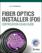
Light entering the core of an optical fiber from outside of the acceptance cone will either miss the core or enter at an angle that will allow it to pass through the boundary with the cladding and be lost, as shown in Figure 8.1. Light entering the core of the optical fiber at an angle greater than the acceptance angle will not propagate the length of the optical fiber. For light to propagate the length of the optical fiber, it must enter at an angle that does not exceed the acceptance angle.
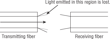
Figure 8.1 When NA mismatch loss occurs, the receiving optical fiber cannot gather all of the light emitted by the transmitting fiber.
The exact loss from an NA mismatch is difficult to calculate. Factors such as light source type, light source launch condition, optical fiber length, and bends in the optical fiber all affect the potential loss. It is possible to have an NA mismatch between two optical fibers and no loss resulting from the mismatch.
Core Diameter Mismatch
Core diameter mismatch occurs when there is a difference in the core diameters of the two optical fibers. A core diameter mismatch loss results when the core diameter of the transmitting optical fiber is greater than the core diameter of the receiving optical fiber, as shown in Figure 8.2. A loss occurs when light at the outer edge of the transmitting optical fiber core falls outside the diameter of the receiving optical fiber core. This light is lost in the cladding of the receiving optical fiber. Core diameter mismatch loss is typically only a concern with multimode optical fiber.
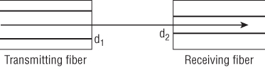
Figure 8.2 Core diameter mismatch loss is the result of the transmitting optical fiber having a larger core diameter than the receiving optical fiber.
It is not uncommon for two multimode optical fibers with different core diameters to be spliced together. As you saw in Chapter 5, ANSI/TIA-568-C.3 recognizes multimode optical fibers with 50μm cores and 62.5μm cores. We can calculate the worst-case loss percentage for a splice that joins a 50μm core and 62.5μm core using this formula:
- Loss = (d12 – d22) / d22
where d1 is the diameter of the transmitting core and d2 is the diameter of the receiving core.
- 62.52 – 502 = 1406.25
- 1406.25/502 = 0.5625 or 56.25%
Using the following formula, the decibel loss can be calculated:
- dB = 10Log10(Pout / Pin)
Note that the decibel formula is a ratio where the power output (Pout) is divided by the power input (Pin). In this case, the power input is the power being put into the receiving optical fiber. We know that the receiving optical fiber will not accept 56.25 percent of the light from the transmitting optical fiber. Subtracting 56.25 percent from 100 percent, as shown next, results in a difference of 43.75 percent, which can be written as 0.4375.
- 100% – 56.25% = 43.75% or 0.4375
- 10Log10 (0.4375 / 1) = –3.59dB
- Loss = 3.59dB
The 3.59dB loss that we just calculated is the maximum loss possible from the core diameter mismatch. The actual loss may vary depending on factors such as light source type, light source launch condition, optical fiber length, and bends in the optical fiber.
Mode Field Diameter Mismatch
Mode field diameter is only a concern in single-mode optical fibers. It describes the diameter of the light beam traveling through the core and a portion of the inner cladding. Values for the mode field diameter are defined by wavelength with longer wavelengths typically having a larger diameter than shorter wavelengths. A typical mode field diameter nominal range is 8.6 to 9.55μm at 1310nm and 8 to 11μm at 1550nm.
A mode field diameter mismatch occurs when there is a difference in the mode field diameters of two single-mode optical fibers. A mode field diameter mismatch loss results when the mode field diameter of the transmitting optical fiber is greater than the mode field diameter of the receiving optical fiber, as shown in Figure 8.3. A loss occurs when optical fiber with the smaller mode field diameter will not accept all of the light from the optical fiber with the larger mode field diameter.

Figure 8.3 Mode field diameter mismatch loss is the result of the transmitting optical fiber having a larger mode field diameter than the receiving optical fiber.
Cladding Diameter Mismatch
Cladding diameter mismatch occurs when the cladding diameters of the transmit and receive optical fibers are not the same. Cladding diameter mismatch loss occurs when the cores of the optical fiber are not aligned because of the cladding diameter mismatch, as shown in Figure 8.4. A cladding diameter mismatch can cause the light exiting the core of the transmitting optical fiber to enter the cladding of the receiving optical fiber. The light entering the cladding is lost, causing attenuation.
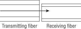
Figure 8.4 Cladding diameter mismatch loss results from differing cladding diameters.
Concentricity
Ideally, the core and cladding of an optical fiber are perfectly round and concentric, which means that they share a common geometric center. However, optical fibers are not perfect and there will be concentricity variations. These concentricity variations can cause the optical fiber cores to misalign, as shown in Figure 8.5, causing a loss when the light exiting the core of the transmitting optical fiber enters the cladding of the receiving optical fiber.

Figure 8.5 Off-center fiber cores cause concentricity loss.
The illustration in Figure 8.5 is greatly exaggerated to clearly show how a concentricity loss may occur. The core and cladding concentricity differences are typically less than 1μm.
Noncircularity
Just as the core and cladding of an optical fiber may not be perfectly concentric, they may also not be perfectly circular. The noncircularity of the core will cause a loss when light from the core of the transmitting optical fiber enters the cladding of the receiving optical fiber. In Figure 8.6, the core is elliptical to show how core noncircularity loss occurs.

Figure 8.6 Noncircularity loss takes place when the ellipticities of two optical fibers do not match exactly.
Cladding noncircularity may cause loss when it causes part of the core of the transmitting optical fiber to align with the cladding of the receiving optical fiber. Any light that enters the cladding of the receiving optical fiber will be lost, causing attenuation.
Note that the amount of loss depends on the alignment of the ellipticities of the two cores. Maximum loss occurs when the long or major axes of the cores are at right angles to one another, and minimum loss occurs when the axes of the cores are aligned. After reading about all the possible intrinsic losses, you may find it hard to believe that two optical fibers can be spliced together with virtually no loss. Optical fiber manufacturing produces optical fibers with little variation, as shown in Tables 8.1, 8.2, 8.3, and 8.4. These tables list the attributes and tolerances for different single-mode optical fibers as defined in ITU standards ITU-T G.652, ITU-T G.655, and ITU-T G.657.
Table 8.1 ITU-T G.652, single-mode optical fiber attributes
| G.652.A, G.652.B, G.652.C, and G.652.D | ||
| Fiber attributes | Detail | Value |
| Mode field diameter | Wavelength | 1310nm |
| Range of nominal values | 8.6–9.5μm | |
| Tolerance | ±0.6μm | |
| Cladding diameter | Nominal | 125.0μm |
| Tolerance | ±1μm | |
| Core concentricity error | Maximum | 0.6μm |
| Cladding noncircularity | Maximum | 1% |
Table 8.2 ITU-T G.655.C, non-zero-dispersion-shifted single-mode optical fiber and cable
| ITU-T G.655.C | ||
| Fiber attributes | Detail | Value |
| Mode field diameter | Wavelength | 1550nm |
| Range of nominal values | 8–11μm | |
| Tolerance | ±0.7μm | |
| Cladding diameter | Nominal | 125.0μm |
| Tolerance | ±1μm | |
| Core concentricity error | Maximum | 0.8μm |
| Cladding noncircularity | Maximum | 2% |
Table 8.3 ITU-T G.655.D, non-zero-dispersion-shifted single-mode optical fiber and cable
| ITU-T G.655.D | ||
| Fiber attributes | Detail | Value |
| Mode field diameter | Wavelength | 1550nm |
| Range of nominal values | 8–11μm | |
| Tolerance | ±0.6μm | |
| Cladding diameter | Nominal | 125.0μm |
| Tolerance | ±1μm | |
| Core concentricity error | Maximum | 0.6μm |
| Cladding noncircularity | Maximum | 1% |
Table 8.4 ITU-T G.657, bending loss-insensitive single-mode optical fiber and cable
| ITU-T G.657 Categories A and B | ||
| Fiber attributes | Detail | Value |
| Mode field diameter | Wavelength | 1310nm |
| Range of nominal values | 8.6–9.5μm | |
| Tolerance | ±0.4μm | |
| Cladding diameter | Nominal | 125.0μm |
| Tolerance | ±0.7μm | |
| Core concentricity error | Maximum | 0.5μm |
| Cladding noncircularity | Maximum | 1% |
Extrinsic Factors
Extrinsic factors that affect optical fiber splice performance are factors related to the condition of the splice itself, external to the optical fiber. In an ideal splice, the optical fibers are identical and they are aligned so that cores are perfectly centered on each other and the core axes are perpendicular to the endfaces being joined, as shown in Figure 8.7. However, there is no such thing as an ideal splice, only a real splice. In a real splice, intrinsic and extrinsic factors affect splice performance.

Figure 8.7 Conditions for an ideal splice
In this section, we will examine common extrinsic factors that affect splice performance. As you read about these extrinsic factors, keep in mind that many times they are caused by dirt and contamination. Microscopic particles of dirt can cause the misalignment of one or both optical fibers, creating a high-loss splice.
Lateral Misalignment
Lateral misalignment occurs when the two optical fibers are offset, as shown in Figure 8.8. Lateral misalignment loss occurs when light from the core of the transmitting optical fiber enters the cladding of the receiving optical fiber, creating a loss. As the lateral misalignment increases, less light from the core of the transmitting optical fiber makes its way into the core of the receiving optical fiber, increasing the loss of the splice.
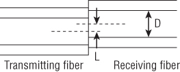
Figure 8.8 Lateral misalignment of the optical fibers
End Separation
Even if the optical fibers are perfectly aligned, the splice still may still experience loss from end separation. End separation is simply a gap between the transmitting and receiving optical fibers, as shown in Figure 8.9.
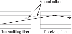
Figure 8.9 End separation is a gap between fiber ends in a mechanical splice.
Two different types of losses can be generated from end separation. The first is through Fresnel reflection, which takes place when light passes from the higher refractive index of the core in the transmitting optical fiber into the lower refractive index of the air, and then back into the core of the receiving optical fiber. Each change in the refractive index causes a certain amount of light to be reflected and therefore lost.
One way to overcome the effects of Fresnel reflections in separated optical fibers is to use an index matching gel, which is a transparent gel having a refractive index close to that of the core of the optical fibers being spliced. The gel fills the gap and reduces or eliminates the Fresnel reflection. Index matching gel is typically used in all mechanical splices.
End separation also causes loss because when light exits the transmitting optical fiber it spreads out like the light from a flashlight. Some of the light leaving the core of the transmitting optical fiber may enter the cladding of the receiving optical fiber, causing a loss. How much the light spreads out depends on several variables, including the distance between the optical fibers, light source type, launch type, length and NA of the transmitting optical fiber, and the bends in the transmitting optical fiber.
Angular Misalignment
If the optical fibers in a splice meet each other at an angle, a loss from angular misalignment may occur, as shown in Figure 8.10. The amount of loss depends on the severity of the angular misalignment and the acceptance cones of the transmitting and receiving optical fibers. Because the NA of a multimode optical fiber is greater than the NA of a single-mode optical fiber, multimode splices tolerate angular misalignment better than single-mode splices.

Figure 8.10 Angular misalignment results when fiber ends are not parallel to each other.
The loss from angular misalignment occurs when light from the core of transmitting optical fiber enters the cladding of the receiving optical fiber or enters the core of receiving optical fiber at an angle exceeding the acceptance angle. Light entering the core of the receiving optical fiber at an angle exceeding the acceptance angle may not propagate the length of the receiving optical fiber.
Angular misalignment also prevents the endfaces from contacting each other, resulting in Fresnel reflections exactly like those described in the “End Separation” section earlier in this chapter. Again, this is why index-matching gel is used with every mechanical splice.
Splicing Safety
As discussed in Chapter 6, “Safety,” you are responsible for your own safety as well as for the safety of your co-workers. It is up to you to know and incorporate safe work practices when splicing optical fibers. Remember, good work habits can help you prevent accidents and spot potential problems in time to correct them.
Here are some general safety rules that are discussed in detail in Chapter 6.
- Keep a clean workspace.
- Observe your surroundings.
- Use tools for the job they were designed to perform.
- Do not eat or drink in the work area.
- Report problems or injuries immediately.
- Know how to reach emergency personnel.
- Put your emergency contact information in your cell phone.
Splicing Hazards
Let's look at some of the hazards directly related to splicing.
Light Sources
Most lasers used in fiber-optic systems emit infrared radiation; you cannot see the beam, no matter how powerful it is. As a result, you will not be able to tell if the system is powered, especially if you are working on a piece of fiber far from the transmitter. Always treat an optical fiber as if it is coupled to a laser unless you can be sure that the fiber is not coupled to a laser.
Handling Fiber
Optical fiber may be flexible; however, it is rigid enough to pierce your skin or eyes and cause discomfort, pain, or damage. If it becomes airborne, you may even accidentally inhale or swallow it, risking damage to your throat or respiratory system. Protect yourself with proper procedures and the right personal protective equipment.
When you cut, cleave, or accidentally break optical fibers, the ends can get lost easily, either by becoming airborne or by rolling along a surface. Whenever possible, work over a nonreflective black mat; it will enable you to more easily identify fiber fragments. In addition, keep track of cut fiber ends and dispose of them in a separate labeled container.
To prevent eye injury, always wear proper eye protection. To prevent injury to your hands, always handle cut pieces of fiber with tweezers. If you have been handling fiber, do not rub your eyes or put your hands near them until you have washed your hands. If you do get a piece of fiber in your skin, remove it immediately with a pair of tweezers or seek medical attention.
Chemicals
In your work with fiber optics, you will use various types of chemicals; each poses a number of hazards and should be handled carefully. Every chemical that you use should be accompanied by a material safety data sheet (MSDS), which provides important information on the chemical's properties and characteristics such as appearance, odor, and common uses. The MSDS also gives you information on specific hazards posed by each chemical and ways to protect yourself through specific handling procedures, protective clothing and equipment, and engineering controls such as ventilation. Finally, the MSDS describes emergency procedures, including first aid for exposure to the chemical, methods for fighting fires in the case of flammable chemicals, and cleanup procedures for spills.
Even if you think you're familiar with the chemicals you handle, take time to read the MSDS. The information you gain could help prevent an accident or save valuable time in an emergency.
Electrical
Unlike mechanical slicing, fusion splicing uses a high-voltage electric arc between two electrodes to heat and melt the fiber ends as shown in Figure 8.11. Touching the electrodes while the arc is present can cause severe electrical shock. Remember that high voltage causes most of its damage by making muscles seize up, including the heart and lungs.
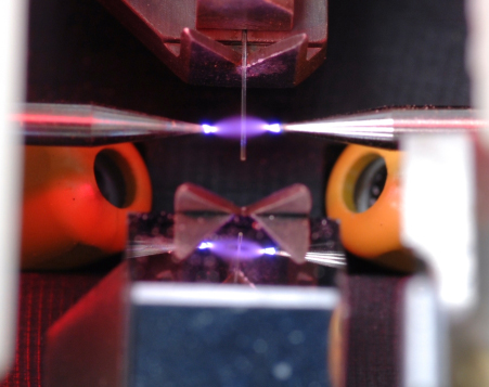
Figure 8.11 Close-up of a high-voltage electric arc melting the fiber ends during the splicing process
Photo courtesy of Aurora Optics
Fusion splicers like the one shown in Figure 8.12 have a cover that prevents access to the splicing area during the splicing process. This device typically has a safety interlock that interrupts the splicing process if lifted. Do not attempt to gain access to the splicing area until after the arc on the fusion splicer display shown in Figure 8.13 is extinguished. The arc is extinguished when it no longer appears on the display, as shown in Figure 8.14.

Figure 8.12 Automatic fusion splicer with the cover closed over the splicing area
Photo courtesy of Aurora Optics
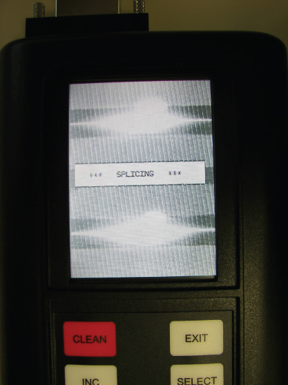
Figure 8.13 Electric arc melting the fiber ends during the splicing process shown on the fusion splicer display
Photo courtesy of Aurora Optics
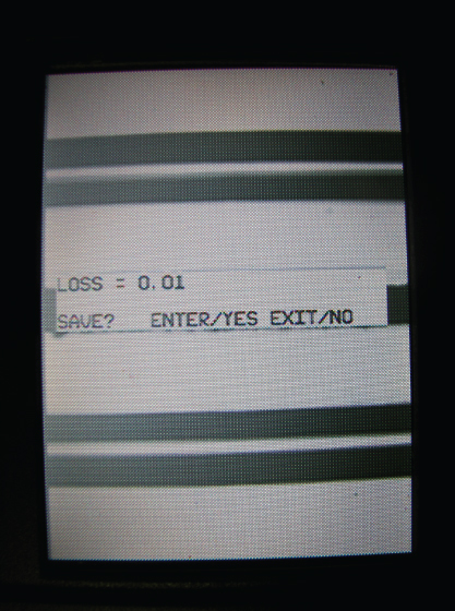
Figure 8.14 Fusion splicer display after the arc is extinguished
Photo courtesy of Aurora Optics
Explosion
Prior to fusion splicing, ensure you are not in a potentially explosive atmosphere. Remember the arc generated during the splicing process is essentially a continuous spark capable of igniting flammable vapors such as those produced by an open container of isopropyl alcohol or the refueling of a vehicle. The ignition of these vapors will cause an explosion.
If you are using isopropyl alcohol during fusion splicing, keep it a safe distance from the fusion splicer and work in a well-ventilated area. Do not initiate the fusing process in the presence of a high concentration of isopropyl alcohol vapors.
In Chapter 7, “Fiber-Optic Cables,” you learned that the aerospace and avionics industries are incorporating more optical fiber in aircraft. This is evident with the Boeing 787 Dreamliner, which has 110 fiber-optic links and over 1.7km of fiber-optic cable. As more commercial and military aircraft install optical fiber, there will be a need for fusion splicing.
A fueled aircraft is a hazardous environment for fusion splicing and special precautions must be taken prior to splicing. Only a fusion splicer like the one shown in Figure 8.15, developed specifically for explosion-proof operation, can be used in hazardous environments such as near a fueled aircraft.

Figure 8.15 Fusion splicer developed specifically for use in hazardous environments
Photo courtesy of Aurora Optics
Splicing Equipment
The goal of any splice is to join two optical fiber endfaces together with as little loss as possible. This can be accomplished through mechanical or fusion splicing. This section describes the equipment required to perform a mechanical or fusion splice.
Cleaning Materials
One of the keys to performing a successful fiber-optic splice is cleanliness. The optical fiber needs to be properly cleaned prior to cleaving and splicing. In addition, the splicing area should be kept as clean as possible. As discussed earlier in the chapter, a microscopic piece of dirt could cause lateral displacement, end separation, or angular misalignment.
Prior to starting any splice, ensure you have lint-free wipes designed for optical fiber; a solvent designed to clean and remove the coating residue from the optical fiber; and if you will be fusion splicing, swabs to clean the V-groove. Lint-free wipes like those shown in Figures 8.16 and 8.17 are engineered to lift away oils, grime, and dust from the surface of the optical fiber.

Figure 8.16 A container of lint-free wipes engineered for cleaning optical fibers
Photo courtesy of MicroCare

Figure 8.17 Packages of lint-free wipes engineered for cleaning optical fibers
Photo courtesy of ITW Chemtronics
When handling a lint-free wipe, be sure to only touch one side of the wipe because the wipe will absorb the oil from your skin. Use the side of the wipe that you did not touch for cleaning the optical fiber. You do not want to contaminate the optical fiber during the cleaning process. Cleaning of the optical fiber is covered in depth later in the “Splicing Procedures” section.
When you select an optical fiber cleaning solvent, ensure it has been engineered to clean optical fibers. The goal is to select a solvent that leaves little or no residue on the surface of the optical fiber. If you choose isopropyl alcohol, make sure that it is virtually free of water and has been filtered to remove impurities, like the isopropyl alcohol shown in Figure 8.18. Do not use the isopropyl alcohol commonly available at your local pharmacy; this alcohol contains a large percentage of water and will leave a residue on the optical fiber.

Figure 8.18 Isopropyl alcohol for cleaning optical fibers
Photo courtesy of MicroCare
Isopropyl alcohol poses a problem for air travel because of its flammability. If the splicing job requires air travel, you will not be able to bring isopropyl alcohol on the aircraft. For jobs requiring air travel, you need to select a cleaning fluid that is approved for air travel. Remember from Chapter 6 that isopropyl alcohol vapors are highly flammable and can ignite if exposed to a spark or flame in high enough concentrations.
Cleaning fluids like the one shown in Figure 8.19 are approved for air travel and engineered specifically to clean the optical fibers. These cleaning fluids typically contain little or no isopropyl alcohol and have been filtered to remove microscopic contaminates.

Figure 8.19 Optical fiber cleaning fluid approved for air travel
Photo courtesy of MicroCare
As will be discussed later in this chapter, many fusion splicers have a precision V-groove that holds the optical fiber. Dirt or contamination in a V-groove can cause the optical fibers to misalign resulting in a high-loss fusion splice. When the V-grooves become contaminated, they can be cleaned using a fiber-optic swab, as shown in Figure 8.20.

Figure 8.20 Cleaning the V-groove with a fiber-optic swab
Photo courtesy of ITW Chemtronics
MicroCare, ITW Chemtronics, Corning Cable Systems, and AFL Telecommunications manufacture some of the most commonly used cleaning materials.
- MicroCare
www.microcare.com - ITW Chemtronics
www.chemtronics.com - Corning
www.corningcablesystems.com - AFL Telecommunications
www.afltele.com
Cleavers
A cleaver is required for all splice types. Cleavers are available for single optical fibers or both single and ribbon fibers. Cleavers that support both single and ribbon fibers have removable adapters designed specifically for single fiber or ribbon fiber cleaving. An adapter is not inserted in the cleaver shown in Figure 8.21. A single fiber adapter is inserted in the cleaver shown in Figure 8.22.

Figure 8.21 Single or ribbon fiber cleaver without the adapter
Photo courtesy of KITCO Fiber Optics

Figure 8.22 Single or ribbon fiber cleaver with the single fiber adapter inserted
Photo courtesy of KITCO Fiber Optics
Cleaving is typically a two-step process, and it takes place after the optical fiber has been properly prepared and cleaned. The first step in the process is scoring the optical fiber. This is accomplished with a scoring blade. The scoring blade should be held perpendicular to the optical fiber, as shown in Figure 8.23. When the cleaver is operated, the scoring blade lightly contacts the optical fiber, creating a small surface flaw.

Figure 8.23 Scoring blade ready to score the optical fiber
Drawing courtesy of Corning Cable Systems
After the optical fiber is scored, the next step is to bend the optical fiber. The optical fiber is bent slightly, as shown in Figure 8.23. Slightly bending the optical fiber places tensile stress on the surface of the optical fiber where it has been scored. This causes the small surface flaw to open and split the fiber.
After the optical fiber is cleaved, the endface should be perpendicular to the optical fiber without any surface defects and the cleave angle should not exceed 1.0°. Cleave angles can be evaluated only with a microscope. This is typically only done when a fusion splice is performed. Many fusion splicers will measure the cleave angle of the optical fiber prior to splicing.
Figure 8.24 is a photograph of a cleaved optical fiber with defects. In an ideal cleave, the mirror area would cover the entire endface. However, in this example the mirror area represents only a small portion of the endface. The rest of the endface looks like it was hacked with a sharp object many times. These irregular defects are commonly referred to as hackles.
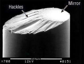
Figure 8.24 Cleaved endface with hackles
Photo courtesy of Corning Cable Systems
Mechanical Splice
Many manufacturers offer mechanical splices. Mechanical splices like the ones shown in Figures 8.25 and 8.26 are typically permanent. They align the cleaved optical fibers and hold them in place. Index matching gel inside the mechanical splice reduces or eliminates Fresnel reflections.
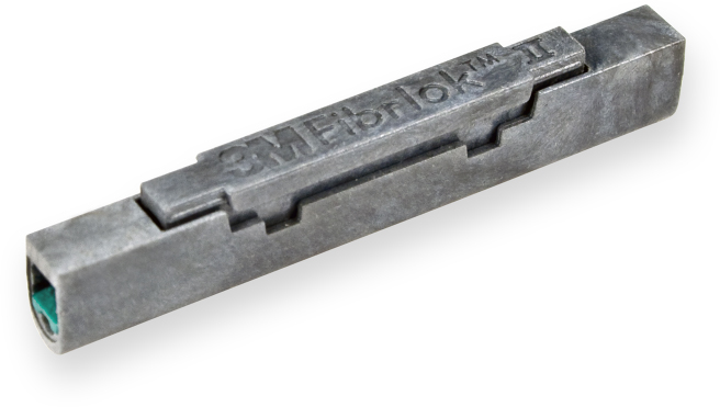
Figure 8.25 3M Fibrlok II universal mechanical splice
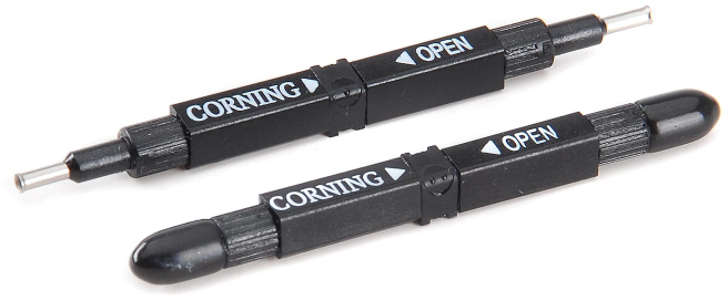
Figure 8.26 Corning CamSplice mechanical splice
Photo courtesy of Corning Cable Systems
Mechanical splices can be used for both multimode and single-mode optical fiber. Mechanical splices do not outperform fusion splices. However, they will outperform mated connector pairs. The key advantage to a mechanical splice over a fusion splice is the low cost of the equipment required to perform the mechanical splice.
The assembly tool that holds the optical fibers and the mechanical splice is relatively inexpensive when compared to the price of a fusion splicer. However, the actual mechanical splices shown in Figures 8.25 and 8.26 cost considerably more than the protective sleeve required for a fusion splice.
Specialty Mechanical Splice
Up to this point, we have only discussed splicing optical fibers that have been cleaved so the endface is perpendicular to the optical fiber. However, angled mechanical splices that offer better return loss performance than traditional mechanical splices are being introduced.
Angled mechanical splices require a special cleaver, angle cleaved fiber holders, and a special mechanical splice. The special cleaver like the one shown in Figure 8.27 places a 7° angle on the fiber endface while the angle cleaved fiber holders maintain the orientation of the cleave. Maintaining the orientation of the cleaved fibers is critical so that they align properly inside the mechanical splice.
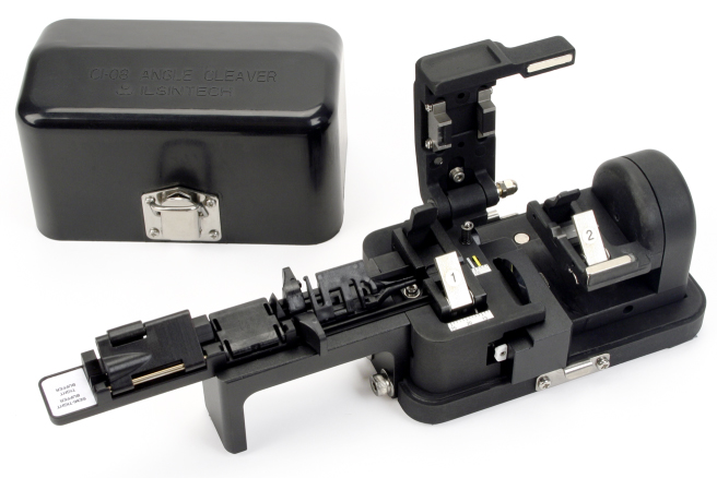
Figure 8.27 3M fiber optic angle cleaver
Photo courtesy of 3M
The angled mechanical splice is an alternative to fusion splicing for analog video transmission, which typically requires lower return loss than a digital transmission. The 7° angle on the fiber endface reflects light into the cladding where it is absorbed. This reduces the amount of light energy that could be reflected back toward the light source, minimizing the back reflection.
Like the traditional mechanical splice, the angled mechanical splice is filled with index matching gel. The combination of the 7° angle and the index matching gel create a mechanical spice that meets or exceeds the return loss requirements for analog video transmission.
3M and Corning Cable Systems manufacture some of the most commonly used mechanical splices.
- 3M
www.3m.com - Corning
www.corningcablesystems.com
Fusion Splice
As you learned earlier in this chapter, fusion splicing uses a high-voltage electric arc between two electrodes to heat and melt the fiber ends as shown in Figure 8.11. This creates a permanent splice that is very fragile and must be protected from the outside environment and bending. This is typically accomplished using heat-shrink tubing and a small metal rod commonly referred to as a protective sleeve.
Prior to performing the splice, the optical fiber is passed through the center of the protective sleeve and the sleeve is positioned so it will not interfere with the fusion splicing process. After the fusion splice is successfully completed, the optical fiber is removed from the fusion splicer and the protective sleeve is positioned directly over the slice area.
The protective sleeve is then placed in an electric oven that is typically built into the fusion splicer. The oven heats the tubing, shrinking it around the fusion splice. The end result looks like the protected fusion splice shown in Figure 8.28.
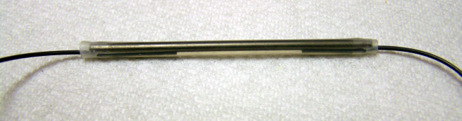
Figure 8.28 A fusion splice covered with heat shrink held rigid with a metal rod
Fusion splicers are more expensive than the assembly tool required for a mechanical splice. However, they provide the lowest-loss splice possible. In addition, fusion splices do not produce Fresnel reflections.
Fusion splicing is the most accurate and durable method for joining two optical fibers. After the optical fibers are stripped and cleaved, they are placed into the fusion splicer, where the optical fibers are aligned between two electrodes, as shown in Figure 8.29. Alignment may be accomplished several ways depending on the type of fusion splicer used.

Figure 8.29 Optical fibers aligned between the fusion splicer electrodes
Drawing courtesy of Corning Cable Systems
Several alignment techniques are used to align the optical fibers. A common alignment technique is to use a fixed V-groove, as shown in Figure 8.30. Each optical fiber is placed in a precision-machined V-groove. The V-grooves align the cladding of the optical fibers. The fusion splicer moves the optical fibers axially into the electric arc, melting the optical fibers together. This type of fusion splicer may be referred to as a passive alignment fusion splicer or a passive v-groove fusion splicer.

Figure 8.30 Optical fibers in a V-groove aligned between the fusion splicer electrodes
Drawing courtesy of Corning Cable Systems
Fusion splicers with this type of alignment system have the lowest cost and are typically the smallest and lightest. However, they align the cladding of the optical fiber instead of the core and can create higher loss splices than fusion splicers that align the cores of the optical fibers.
A fusion splicer that aligns the cores of the optical fibers will produce the lowest-loss splice. However, aligning the cores of the optical fibers is more difficult than aligning two optical fibers placed in V-grooves. To align the cores, the fusion splicer must be able to detect the cores and have the ability to move the optical fibers on each axis. This type of fusion splicer may be referred to as an active alignment fusion splicer.
Several patented technologies are available to detect the cores of optical fibers. Because they are patented, they will not be discussed in detail in this chapter.
Fusion splicers on the market today typically feature a display that allows you to see the optical fibers on two different axes. The cameras in the fusion splicer magnify the optical fibers so that the endfaces can be evaluated. You cannot look at an optical fiber with the naked eye and evaluate the endface. Without magnification, optical fiber with a perfect cleave will look just like an optical fiber that has been broken. Figure 8.31 is a photograph of a fusion splicer display showing a two-axis view of properly cleaved and aligned optical fibers. Shown in Figure 8.32 is a two-axis view of two broken optical fibers. This photograph clearly shows that a broken optical fiber can have a jagged endface.
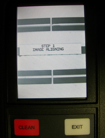
Figure 8.31 Properly cleaved and aligned optical fibers viewed on the display of a fusion splicer
Photo courtesy of Aurora Optics
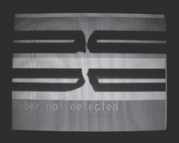
Figure 8.32 Optical fibers with jagged endfaces viewed on the display of a fusion splicer
Most fusion splicers available today also have the ability to approximate the loss for the splice after it is completed. Fusion splicers are also available that have the ability to measure the loss for the splice after it is completed. Figure 8.33 is a photograph of a fusion splicer display showing the estimated splice loss. The splice loss is displayed on the bottom of the screen, and different axis views of the spliced optical fiber are shown at the top of the screen. Note that the spliced optical fibers appear as a single optical fiber with no flaws.
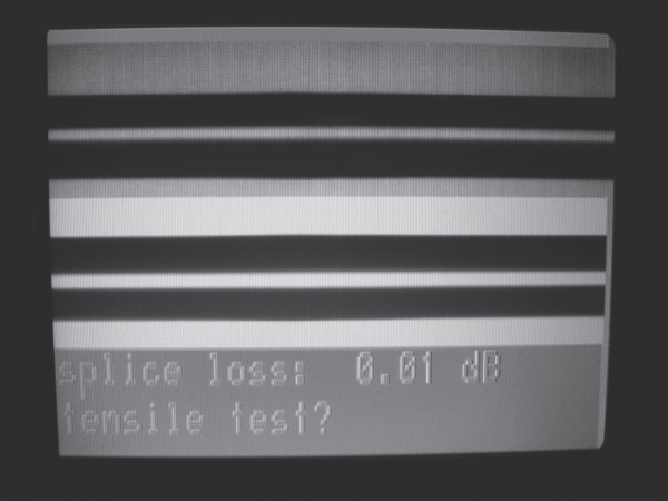
Figure 8.33 Fusion splicer displaying the estimated splice loss
You can find out more about specific features of fusion splicers through their manufacturers' websites. Some of the major manufacturers of fusion splicers are as follows:
- Corning
www.corningcablesystems.com - Aurora Optics
www.aurora-optics.com - AFL Telecommunications
www.afltele.com - Fitel
www.fitel.com
Next let's look at the procedures used with each type of splicer.
Splicing Procedures
This section will familiarize you with the basic procedures used for mechanical or fusion splicing. While manufacturers' models will vary, many of the same principles and requirements apply. Be sure to read and follow the directions for your particular equipment carefully.
Mechanical Splicing Procedure
To prepare for mechanical splicing, make sure that the work area is clean, dry, and well lit. Do all your work over a fiber-optic mat and place any scrap optical fibers in their proper container, as described in Chapter 6. Assemble the following tools before you begin:
- Mechanical splice assembly tool
- Mechanical splice
- Buffer and coating removal tool
- Optical fiber cleaning fluid
- Lint-free wipes
- Cleaver
Once your materials are assembled, clean the cleaver as directed by the manufacturer, and then proceed with the following steps:
- Remove the 3M Fibrlok II mechanical splice from its protective packaging and load the splice into the assembly tool by pressing firmly at the ends of the splice. Do not depress the raised section on the mechanical splice.
- Strip approximately 3cm of buffer and/or coating from the optical fiber using a stripper, as shown in Figure 8.34.
- Clean the optical fiber by pulling the fiber through a lint-free wipe soaked in optical fiber cleaning fluid, as shown in Figure 8.35.
- Place the optical fiber in the cleaver, as shown in Figure 8.36, to the length specified by the mechanical splice manufacturer.
- Cleave the optical fiber.
- If a gauge is provided, check the cleave length with the gauge. If the optical fiber has touched the gauge, repeat step 3.
- Repeat steps 2 through 6 for the other fiber end to be spliced.
- Push one cleaved optical fiber into one end of the mechanical splice until it stops moving.
- Push the other cleaved optical fiber into the other end of the mechanical splice until it stops moving.
- Place both optical fibers in the clamping mechanisms on the opposite sides of the splicing tool, forming a modified loop in the optical fiber, as shown in Figure 8.37.
- Pivot the splicing tool handle down until it contacts the top of the splice; then squeeze the tool handle to complete the assembly and lock the spliced ends in place.
- Remove the optical fibers from the clamping mechanisms and lift the mechanical splice from the tool.
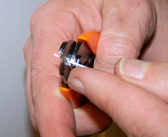
Figure 8.34 Stripping the buffer and coating from an optical fiber

Figure 8.35 Clean the optical fiber by pulling it through the lint-free wipe soaked in optical fiber cleaning fluid.
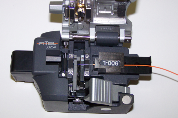
Figure 8.36 Place the optical fiber in the cleaver at the length specified by the manufacturer.
Photo courtesy of KITCO Fiber Optics

Figure 8.37 Mechanical splice tool properly set up to perform a mechanical splice
Mechanical Splicing Troubleshooting
Following the mechanical splicing procedures outlined earlier typically results in a low-loss splice that outperforms the attenuation requirements for inside or outside plant splices. However, occasionally you will encounter a splice that does not meet the attenuation requirement. As you learned earlier, how well a splice performs depends on many variables. These variables can be broken into two groups: intrinsic factors and extrinsic factors.
Intrinsic factors are the result of slight variations from one optical fiber to another. These variations can affect the performance of the splice even though the optical fibers are perfectly aligned when mated. However, the optical fibers available today have very little variation, which means that a small percentage of the splice loss may be from intrinsic factors.
Extrinsic factors are related to the condition of the splice itself, external to the optical fiber. Many times, they are caused by dirt and contamination. Microscopic particles of dirt can cause the misalignment of one or both optical fibers, creating a high-loss splice.
Many mechanical splices can be opened or unlocked so they can be used more than one time in case the initial splice does not meet the attenuation or back reflection requirements. Next we will examine some of the common causes for a high-loss mechanical splice.
Cleave Angle
As you've learned, the endface of a properly cleaved optical fiber should be perpendicular to the optical fiber without any surface defects and the cleave angle should not exceed 1.0°. Cleave angles can be evaluated only with a microscope. Unfortunately, mechanical splicing tools are not equipped with a 2-axis microscope as most fusion splicers are. If you suspect a bad cleave, perform the following steps:
- Open or unlock the splice and remove the optical fibers.
- Prepare the optical fibers for cleaving adhering to the manufacturer's instructions.
- Ensure the optical fiber and cleaver is clean.
- Re-cleave both optical fibers.
- Verify the cleave dimensions as stated in the manufacturer's instructions.
- Reassemble the mechanical splice as described in the manufacturer's instructions.
Cleave Length
Cleave length is just as important as cleave angle. Each mechanical splice manufacturer defines how much bare optical fiber should be exposed after the cleaving process is completed. This dimension is typically provided in millimeters with maximum and minimum values. Exposing too much optical fiber or not enough optical fiber can create a high-loss mechanical splice. If you suspect improper cleave length, follow these steps:
- Open or unlock the splice and remove the optical fibers.
- Prepare the optical fibers for cleaving adhering to the manufacturer's instructions.
- Ensure the optical fiber and cleaver is clean.
- Re-cleave both optical fibers.
- Verify the cleave dimensions as stated in the manufacturer's instructions.
- Reassemble the mechanical splice as described in the manufacturer's instructions.
Contamination
Contamination on the optical fiber or cleaver that is invisible to the unaided eye can cause a mechanical splice to exceed attenuation and back reflection requirements. Because you cannot see the contamination, make sure that you are using the types of cleaning products and the cleaning process required by the splice and cleaver manufacturer or described in this chapter. Never let a cleaned optical fiber touch any surface after cleaving. If you have any cleaning related questions, you can always reach out to a cleaning product manufacturer such as MicroCare or ITW Chemtronics for help.
- MicroCare
www.microcare.com - ITW Chemtronics
www.chemtronics.com
Fusion Splicing Procedure
The equipment required for fusion splicing is far more complex and expensive than the equipment required for mechanical splicing. However, many of the steps required to perform a fusion splice are identical to the steps required to perform a mechanical splice.
Many fusion splicers contain a feature that automatically positions the fiber ends in proper relationship with each other and with the electrodes for the best possible splice. All that is required of the operator is to prepare the fibers properly and place them in the fusion splicer as outlined by the manufacturer.
The fusion-splicing procedures outlined in this chapter describe the typical steps required to fusion-splice single optical fibers and ribbon optical fibers. These steps are not product specific and modifications may be required depending on the fusion splicing equipment being used. Always review the manufacturer's operating documentation prior to performing a splice.
To prepare for fusion splicing, as with mechanical splicing, make sure that the work area is clean, dry, and well lit. Do all your work over a fiber-optic mat and place any scrap optical fibers in their proper container, as described in Chapter 6. Assemble the following tools before you begin:
- Fusion splicer
- Buffer and coating removal tool
- Optical fiber cleaning fluid
- Lint-free wipes
- Cleaver
- Heat-shrink protective covering
Once your materials are assembled, clean the cleaver and the fusion splicer as directed by the manufacturer, and then proceed with the following steps. First, we'll look at single optical fiber fusion splicing:
- Power on the fusion splicer and select the appropriate splicing program or profile for the optical fiber you will be splicing.
- Slide the protective heat-shrink tubing over one optical fiber end and move it far enough up the optical fiber to place it out of the way.
- Strip approximately 3cm of buffer and/or coating from the optical fiber using a stripper, as shown in Figure 8.38.
- Clean the optical fiber by pulling the fiber through a lint-free wipe soaked in optical fiber cleaning fluid, as shown in Figure 8.39.
- Place the optical fiber in the cleaver, as shown in Figure 8.40, to the length specified by the mechanical splice manufacturer.
- Cleave the optical fiber.
- Place the optical fiber in the fusion splicer following the manufacturer's instructions. Position the endface of the optical fiber between the electrodes.
- Repeat steps 3 through 7 for the other fiber end to be spliced. The properly placed fibers should be slightly separated between the electrodes, as shown in Figure 8.41.
- Close the electrode cover.
- Begin the fusion-splicing process.
- Carefully remove the splice and position the heat-shrink tubing from step 2 over it. Place the splice and tubing in the heat-shrink oven to seal and protect the splice.

Figure 8.38 Stripping the buffer and coating from an optical fiber
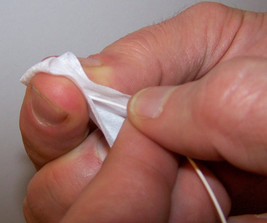
Figure 8.39 Clean the optical fiber by pulling it through the lint-free wipe soaked in optical fiber cleaning fluid.
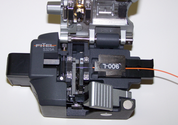
Figure 8.40 Place the optical fiber in the cleaver at the length specified by the manufacturer.
Photo courtesy of KITCO Fiber Optics

Figure 8.41 Properly placed fibers almost touch each other between the electrodes.
Photo courtesy of KITCO Fiber Optics
Next we'll look at ribbon fiber fusion splicing:
- Power on the fusion splicer and select the appropriate splicing program or profile for the optical fiber you will be splicing.
- Slide the protective heat-shrink tubing over one ribbon fiber end and move it far enough up the optical fiber to place it out of the way.
- Strip approximately 3cm of Mylar tape and coating from the ribbon fiber, as shown in Figure 8.42.
- Clean the ribbon fiber by pulling the fiber through a lint-free wipe soaked in optical fiber cleaning fluid, as shown in Figure 8.43.
- Place the ribbon fiber in the cleaver, as shown in Figure 8.44, to the length specified by the manufacturer of splicer you are using.
- Cleave the ribbon fiber.
- Place the ribbon fiber in the fusion splicer, as shown in Figure 8.45. Position the ribbon fiber as described in the manufacturer's instructions.
- Lock the ribbon fiber in place as described in the manufacturer's instructions.
- Repeat steps 3 through 8 for the other fiber end to be spliced.
- Close the electrode cover.
- Begin the fusion-splicing process.
- Carefully remove the splice and position the heat-shrink tubing from step 2 over it. Place the splice and tubing in the heat-shrink oven to seal and protect the splice.
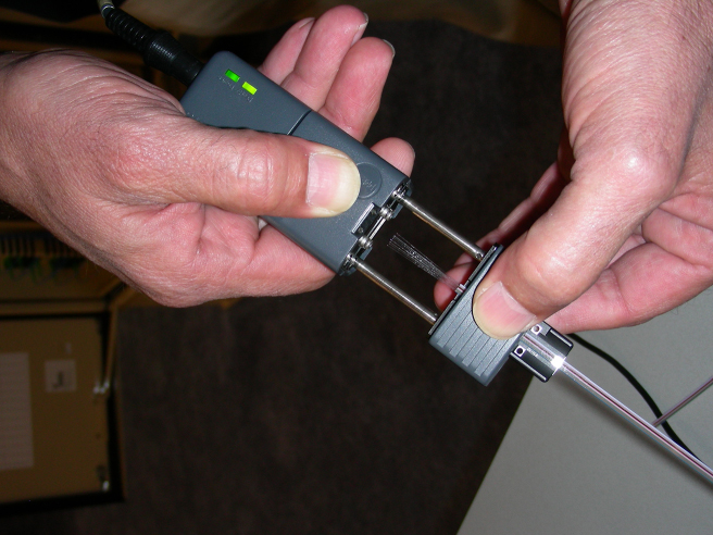
Figure 8.42 Ribbon fiber stripper using heat to remove the Mylar tape and coating
Photo courtesy of MicroCare
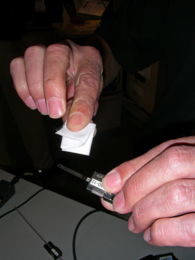
Figure 8.43 Ribbon fiber being pulled through a lint-free wipe soaked in optical cleaning fluid
Photo courtesy of MicroCare
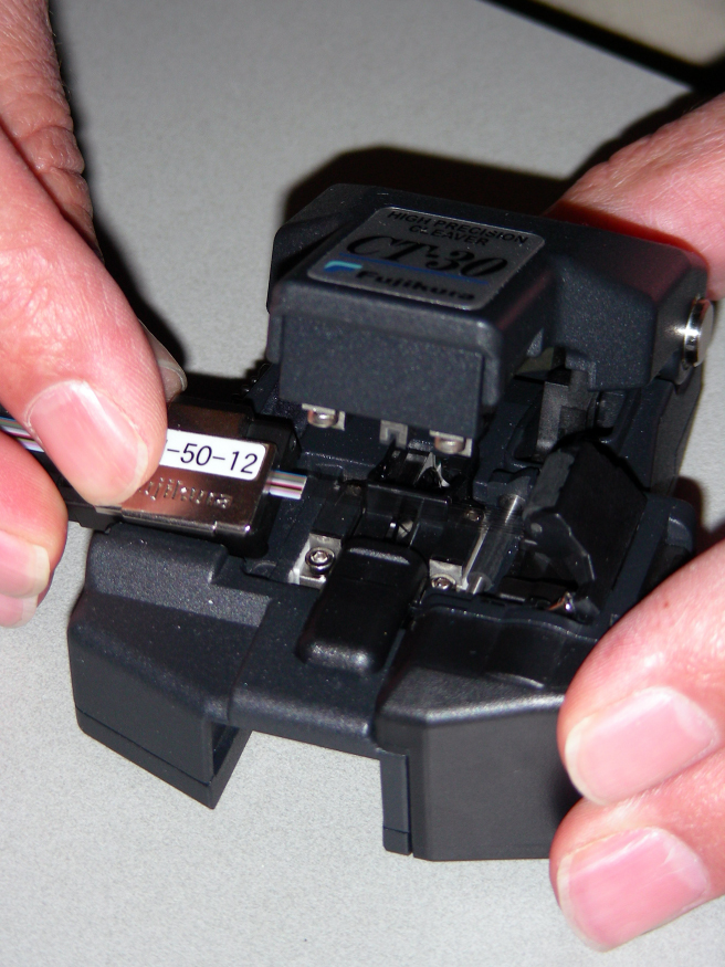
Figure 8.44 Ribbon fiber placed in the cleaver for cleaving
Photo courtesy of MicroCare
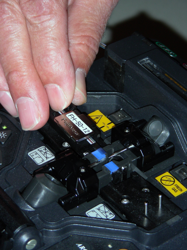
Figure 8.45 Ribbon fiber placed in the fusion splicer for splicing
Photo courtesy of MicroCare
Fusion Splicing Troubleshooting
Following the fusion splicing procedures outlined earlier typically results in a low-loss splice that outperforms the attenuation requirements for inside or outside plant splices. However, occasionally you will encounter a splice that exceeds maximum attenuation requirements. As you've learned, how well a splice performs depends on many variables. As with mechanical splicing, these variables can be broken into two groups: intrinsic factors and extrinsic factors.
Intrinsic factors are the result of slight variations from one optical fiber to another. These variations can affect the performance of the splice even though the optical fibers are perfectly aligned when mated. However, the optical fibers available today have very little variation, which means that a small percentage of the splice loss may be from intrinsic factors.
Extrinsic factors are related to the condition of the splice itself, external to the optical fiber. Many times, they are caused by dirt and contamination. Microscopic particles of dirt can cause the misalignment of one or both optical fibers, creating a high-loss splice.
Next we will examine some of the common causes for a high-loss fusion splice.
Cleave Angle
As discussed earlier, the endface of a properly cleaved optical fiber should be perpendicular to the optical fiber without any surface defects and the cleave angle should not exceed 1.0°. Cleave angles can be evaluated only with a microscope. Fortunately many fusion splicers are equipped with a 2-axis microscope that allows you to observe the cleave and the measured cleave angle values. If you or the fusion splicer detects a bad cleave, as shown in Figure 8.46, perform the following steps:
- Remove the optical fibers from the fusion splicer.
- Prepare the optical fibers for cleaving adhering to the manufacturer's instructions.
- Ensure the optical fiber and cleaver is clean.
- Re-cleave both optical fibers.
- Verify the cleave dimensions as stated in the manufacturer's instructions.
- Place the optical fibers in the fusion splicer following the manufacturer's instructions. Position the endface of the optical fibers between the electrodes.
- Perform the fusion splice.
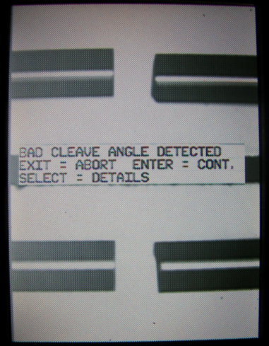
Figure 8.46 Improperly cleaved optical fibers viewed on the display of a fusion splicer
Photo courtesy of Aurora Optics
Cleave Length
Cleave length is just as important as cleave angle. Each fusion splice manufacturer defines how much bare optical fiber should be exposed after the cleaving process is completed. This dimension is typically provided in millimeters with maximum and minimum values. Exposing too much optical fiber or not enough optical fiber can create a high-loss fusion splice. If you suspect improper cleave length, follow these steps:
- Remove the optical fibers from the fusion splicer.
- Prepare the optical fibers for cleaving, adhering to the manufacturer's instructions.
- Ensure the optical fiber and cleaver is clean.
- Re-cleave both optical fibers.
- Verify the cleave dimensions as stated in the manufacturer's instructions.
- Place the optical fibers in the fusion splicer, following the manufacturer's instructions. Position the endface of the optical fibers between the electrodes.
- Perform the fusion splice.
Bubbles
Dirt or entrapped air may create a bubble or bubbles, resulting in a high-loss fusion splice like the one shown in Figure 8.47. To prevent bubbles
- Ensure you are using the types of cleaning products and the cleaning processes required by the fusion splicer and cleaver manufacturer or described in this chapter.
- Verify that you have selected the appropriate splicing program or profile for the optical fiber you are splicing.
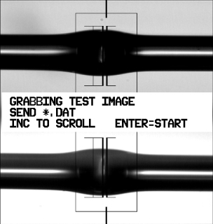
Figure 8.47 Bubbles in a high-loss fusion splice viewed on the display of a fusion splicer
Photo courtesy of Aurora Optics
Necking
Necking is a term used to describe a fusion splice where the diameter of the fused optical fiber is smaller near the electrodes than it was prior to being fused, as shown in Figure 8.48. Necking is typically the result of too much heat during the prefuse, causing glass to be transported away from the splice area and thus producing a high-loss splice. To prevent necking
- Ensure you are using the types of cleaning products and the cleaning processes required by the fusion splicer and cleaver manufacturer or described in this chapter.
- Verify that you have selected the appropriate splicing program or profile for the optical fiber you are splicing.
- Ensure the optical fibers are properly cleaved.

Figure 8.48 A high-loss fusion splice caused by necking viewed on the display of a fusion splicer
Photo courtesy of Aurora Optics
Contamination
Contamination on the optical fiber or cleaver that is invisible to the unaided eye can cause fusion splices to exceed attenuation requirements. Because you cannot see the contamination, make sure that you are using the types of cleaning products and the cleaning process required by the fusion splicer and cleaver manufacturer or described in this chapter. Never let a cleaned optical fiber touch any surface after cleaving. If you have any cleaning-related questions, you can always reach out to a cleaning product manufacturer such as MicroCare or ITW Chemtronics for help.
- MicroCare
www.microcare.com - ITW Chemtronics
www.chemtronics.com
Splice Performance Requirements
As with connectors, standards specify a maximum permissible loss for splices, depending on their location. ANSI/TIA-568-C.3 addresses the performance of fusion or mechanical splices for premises applications, also known as inside plant applications. The standard states that a fusion or mechanical splice shall not exceed a maximum optical insertion loss of 0.3dB when measured in accordance with ANSI/EIA/TIA-455-34-A, Method A (factory testing), or ANSI/TIA-455-78-B (field-testing).
ANSI/TIA-568-C.3 also defines the minimum return loss for mechanical or fusion optical fiber splices. Multimode mechanical or fusion splices shall have a minimum return loss of 20dB while single-mode mechanical or fusion splices shall have a minimum return loss of 26dB when measured in accordance with ANSI/TIA/EIA-455-107-A. The minimum single-mode return loss for broadband analog video CATV applications is 55dB when measured in accordance with ANSI/TIA/EIA-455-107-A.
ANSI/TIA-758-B specifies the minimum performance requirements for mechanical or fusion splices for outside plant applications. It states that the splice insertion loss shall not exceed 0.1dB mean, with a maximum of 0.3dB, as measured with an optical time-domain reflectometer (described in Chapter 14, “Test Equipment and Link/Cable Testing”).
Return loss performance requirements for mechanical or fusion splices are also defined in ANSI/TIA-758-B. Either type of splice shall have a return loss greater than or equal to 45.0dB mean, 40.0dB minimum, when measured in accordance with ANSI/TIA/EIA-455-8.
SAE International published AS6479 in January 2014. This aerospace standard defines fusion splicers acceptable for aerospace applications. It also defines splice insertion loss requirements. This standard is different from ANSI/TIA-568-C.3 and ANSI/TIA-758-B because it defines the performance of the fusion splicer, not the performance of the as installed splice.
Under laboratory conditions, a fusion splicer compliant with AS6479 must be able to splice single-mode optical fibers with a mean insertion loss of 0.03dB or better. It must also be able to splice multimode optical fibers with a mean insertion loss of 0.02dB or better. These mean insertion loss values apply to passive and active alignment fusion splicers.
Telcordia GR-765 is a telecommunications document that provides requirements for single fiber, single-mode optical fiber splicing. Like AS6479, this document contains criteria governing the ability of fusion splicing equipment to assemble complete splices. It specifies required and objective splice insertion loss values for passive alignment and active alignment fusion splicers.
For passive alignment fusion splicers, the GR-765 required mean insertion loss is ≤0.15dB and the objective mean insertion loss is ≤0.10dB. For active alignment fusion splicers, the required mean insertion loss is ≤0.10dB and the objective mean insertion loss is ≤0.05dB.
Summary
This chapter examined the intrinsic and extrinsic factors that can affect splice performance. It described the hazards associated with mechanical and fusion splicing. In addition, it introduced the tools and equipment required to perform splicing.
We also learned how to use the tools and equipment to assemble a mechanical or fusion splice. In addition, we learned how to troubleshoot a splice and the maximum permissible insertion and return loss values for inside plant and outside plant splices.
Exam Essentials
- Understand the intrinsic factors affecting splice performance. Make sure you understand how optical fiber manufacturing variations can affect splice performance. Be able to describe the different intrinsic factors.
- Understand the extrinsic factors affecting splice performance. Make sure you understand how the physical relationship between the optical fibers can affect splice performance. Be able to describe the different extrinsic factors.
- Be familiar with the different types of splices. Make sure you can explain the difference between a mechanical splice and a fusion splice. Be able to describe the equipment used to assemble them. In addition, be able to describe the benefits and drawbacks of each type of splice.
- Be familiar with splicing procedures. Make sure you understand the basic steps for assembling each type of splice. Be able to describe the tools and procedures required for each type of splice.
- Understand splice performance specifications. Make sure you know the maximum permissible insertion and return loss for inside and outside plant mechanical and fusion splices.
Review Questions
- NA mismatch loss occurs when
A. The numerical aperture of the transmitting optical fiber is smaller than that of the receiving fiber.
B. The numerical aperture of the transmitting optical fiber is larger than that of the receiving fiber.
C. The numerical apertures of both optical fibers are larger than normal.
D. The numerical apertures of both optical fibers are smaller than normal.
Hint: Light enters at an angle that exceeds the acceptance angle.
- Core diameter mismatch loss occurs when
A. The diameter of the transmitting core is greater than that of the receiving core.
B. The diameter of the transmitting core is less than that of the receiving core.
C. The diameter of the transmitting core is not precisely aligned with the diameter of the receiving core.
D. The diameter of the transmitting core is equal to the diameter of receiving core.
Hint: Light will be lost in the cladding of the receiving optical fiber.
- Cladding diameter mismatch loss will not occur when
A. The cladding diameter of the transmitting fiber is larger than the cladding of the receiving fiber.
B. The cladding diameter of the transmitting fiber is smaller than the cladding of the receiving fiber.
C. The cladding diameters of both optical fibers are identical.
D. The cladding diameters of both optical fibers are not the same.
Hint: Light will be lost in the cladding of the receiving optical fiber.
- Which is not an intrinsic factor that affects splice performance?
A. Noncircularity
B. Mode field diameter mismatch
C. Concentricity
D. Lateral misalignment
Hint: It is external to the optical fibers.
- Which is not an extrinsic factor that affects splice performance?
A. End separation
B. Concentricity
C. Angular misalignment
D. Lateral misalignment
Hint: The core and cladding should share a common geometric center.
- A mechanical splice typically uses _________________ to reduce or eliminate Fresnel reflections.
A. Epoxy
B. A high-voltage electric arc
C. Index matching gel
D. Isopropyl alcohol
Hint: It should have the same refractive index as the optical fiber core.
- A fusion splicer uses _________________ to produce a low loss splice.
A. Epoxy
B. A high-voltage electric arc
C. Index matching gel
D. An angled cleaver
Hint: It generates heat.
- Cleaving is typically a _________________ process.
A. One-step
B. Two-step
C. Three-step
D. Four-step
Hint: Bending the optical fiber places tensile stress on the cladding surface.
- When should the optical fiber be passed through the center of the protective sleeve?
A. Before fusion splicing
B. While fusion splicing
C. During cable installation
D. After fusion splicing
Hint: It should be positioned directly over the splice area.
- ANSI/TIA-568-C.3 states that optical fiber splices, whether fusion or mechanical, will have a maximum attenuation of _________________.
A. 0.1dB
B. 0.3dB
C. 0.5dB
D. 0.75dB
Hint: It is less than the maximum loss for a mated pair.
Chapter Exercises
Determine if the Splice Loss Is from an Intrinsic Factor
Even when fibers are manufactured within specified tolerances, there are still slight variations from one optical fiber to another. These variations can affect the performance of the splice even though the optical fibers are perfectly aligned when mated.
Two optical fibers are about to be fusion spliced together, as shown here. Determine what type of problem exists with the optical fibers about to be spliced.

A close inspection of the graphic reveals that the core diameter of the left optical fiber is slightly smaller than the right optical fiber. This core diameter mismatch is the result of an intrinsic factor.
Determine if the Splice Loss Is from an Extrinsic Factor
Extrinsic factors that affect optical fiber splice performance are factors related to the condition of the splice itself, external to the optical fiber.
Two optical fibers are about to be fusion spliced together, as shown here. Determine what type of problem exists with the optical fibers about to be spliced.

A close inspection of the graphic reveals that there is some angular misalignment. The angular misalignment is the result of an extrinsic factor.
Calculate the Potential Splice Loss from a Core Diameter Mismatch
A core diameter mismatch loss results when the core diameter of the transmitting optical fiber is greater than the core diameter of the receiving optical fiber.
Calculate the worst-case loss for a splice where the transmitting optical fiber has a core diameter of 51μm and the receiving optical fiber has a core diameter of 49.5μm.
We can calculate the worst-case loss percentage for a splice that joins a 50.5μm core and 49.5μm core using the following formula:
- Loss = (d12 – d2)2 / d22
where d1 is the diameter of the transmitting core and d2 is the diameter of the receiving core.
- 50.52 – 49.52 = 100
- 100/49.52 = 0.0408 or 4.08%
Using this formula, the decibel loss can be calculated:
- dB = 10Log10(Pout / Pin)
Note that the decibel formula is a ratio, where the power output is divided by the power input. We know that the receiving optical fiber will not accept 4.08 percent of the light from the transmitting optical fiber. Subtracting 4.08 percent from 100 percent, as shown here, results in a difference of 95.92 percent, which can be written as 0.9592.
- 100% – 4.08% = 95.92% or 0.9592
- 10Log10 (0.9592 / 1) = –0.181dB
- Worst-case loss = 0.181dB
Troubleshoot a Fusion Splice
How well a splice performs depends on many variables. These variables can be broken into two groups: intrinsic factors and extrinsic factors.
Two optical fibers have been fused together as shown here. Determine the type of problem and potential causes.

A close inspection of the of the fusion splicer display reveals that the optical fiber ends that have been joined are larger in diameter than the optical fiber. This is typically caused by dirt or entrapped air creating a bubble or bubbles. The result is a high-loss fusion splice. To prevent bubbles, verify that you have selected the appropriate splicing program or profile for the optical fiber you are splicing and ensure you are properly cleaning the fusion splicer and cleaver.