Appendix: Answers to Review Questions
Chapter 1: History of Fiber Optics and Broadband Access
- B. Light travels at approximately 300,000 kilometers per second in air, and it allowed simple messages to be sent quickly over great distances through the use of signal fires.
- C. The demonstrations performed by Colladon, Babinet, and Tyndall proved that light could be guided through water if the air around it had a lower index of refraction. This demonstrated the principle of total internal reflection.
- A. Doctors and researchers experimented with bent glass and quartz to create a device that would allow them to see inside the body with minimal intrusion.
- D. In 1966, Charles K. Kao announced that signal losses in glass fibers could be reduced to 20 decibels per kilometer or less through improved manufacturing processes. This announcement was the beginning of a quest for lower and lower signal loss through optical fiber.
- D. The first full-scale commercial application of fiber-optic communication systems occurred in 1977, when both AT&T and GTE began using fiber-optic telephone systems for commercial customers.
- A. Without fiber optics, broadband as we know it today would not exist. No other transmission medium can move the high rates of data over the long distances required to support the global telecommunications system.
Chapter 2: Principles of Fiber-Optic Transmission
- B. The fiber optic link requires a transmitter to send the signal, a receiver to capture the signal, optical fiber to carry the signal, and connectors to align the fiber end precisely with the light source or photodiode.
- D. In order for a signal to be transmitted through optical fiber, the transmitter must convert it from electrical energy into light.
- D. With each 10 decibels of loss, the power remaining is 10 percent of what it was.
- C. The receiver captures the light and converts it back to an electrical signal.
- A. To calculate the decibel value for the loss in signal power, use the following equation:
- D. To calculate the loss in power from the optical fiber and the output power of the optical fiber, solve first for the loss and then for the output power. The equation would be written as follows:
- B. Decibels can be algebraically added and subtracted, 10dB + 10dB + 3dB = 23dB.
- C. To calculate the power in watts, the equation would be written as:
- D. Each 10-decibel loss divides the percentage of remaining power by another factor of 10; 100% ÷ 1,000 = 0.1%.
- D. To calculate the power in dBm, the equation would be written as:
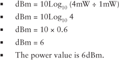
This answer can be checked by locating 4mW in the first column of Table 2.4.
Chapter 3: Basic Principles of Light
- B. The energy takes two forms: an electrical field and a magnetic field, formed at right angles to each other and at right angles to their path of travel.
- A. An electromagnetic wave travels through free space or air at approximately 300,000km/s (kilometers per second).
- C. Light has characteristics of both waves and particles. As a wave, it propagates through a medium and transfers energy without permanently displacing the medium. However, as a massless particle, called a photon, it travels in a wavelike pattern moving at the speed of light.
- B. Wavelength or frequency can be used to describe electromagnetic energy; however, wavelength is typically used to describe the output of a fiber optic light source.
- A. Gamma rays have a shorter wavelength than the other three types of light. Visible light has a longer wavelength than ultraviolet light and a shorter wavelength than infrared light.
- D. The wavelengths most commonly used for fiber optics are in the infrared range, at windows of 850nm, 1300nm, and 1550nm.
- B. Refraction, or the change in the direction of light as it changes speed passing from one material into another, is a key component in fiber-optic transmissions.
- A. The higher the refractive index, the slower the light travels. In other words, the speed of light in a medium is inversely proportional to its index of refraction.
- C. If the light refracts toward normal, we know that the light has slowed down upon entering medium B, so we know that medium A has a lower n than medium B.
- B. Total internal reflection takes place when light passing through a medium with a higher n hits the boundary layer of a medium with a lower n at a shallow angle, causing it to reflect from the boundary layer.
- D. The incident angle required to produce a refracted angle of 90° is called the critical angle.
- A. We can calculate the amount of refraction using Snell's law, which shows the relationship between incident light and refracted light.
- B. When light changes speed as it moves from a material with a given index of refraction into a material with a different index of refraction, a Fresnel reflection occurs.
- C. The greater the difference in the index of refraction between the two materials, the greater the amount of light reflected.
- C. A Fresnel reflection occurs when light changes speed as it moves from the optical fiber to the air and from the air to the optical fiber.
Chapter 4: Optical Fiber Construction and Theory
- B. The core is at the center of the optical fiber; the cladding surrounds the core and the coating surrounds the cladding.
- A. One characteristic of optical fiber that deserves special attention is its tensile strength, or the amount of stress from pulling that the optical fiber can handle before it breaks. Optical fiber has a high tensile strength and resists stretching.
- D. ANSI/TIA-568-C is applicable to premises cabling components and defines the performance of both multimode and single-mode optical fibers.
- B. The material that will become the core and cladding of the glass fiber is originally laid down as a soot produced by burning a gas with the materials in it. The soot is then heated and compressed into the high-quality glass fiber.
- A. Multimode and single-mode depressed clad optical fibers are commonly referred to as bend insensitive.
- B. There are many potential paths or modes light can follow, depending on the size of the core, wavelength of the light source, and numerical aperture.
- A. One of the most important characteristics used to distinguish types of optical fiber is the number of potential paths light can take through it.
- C. Modes are expressed in whole numbers. If the calculation for modes results in a fraction, the result is rounded down to the nearest whole number.
- D. The refractive index profile graphically represents the relationship between the refractive index of the core and that of the cladding.
- B. Modal dispersion is caused when light rays follow different paths in the core of the optical fiber.
- C. Multimode graded-index fiber tackles the problem of modal dispersion by increasing the speed of the high-order mode light rays, allowing them to keep up with the low-order mode rays.
- D. Single-mode fibers use a small core that doesn't give the light enough space to follow anything but a single path through the fiber.
- A. The shortest wavelength at which the optical fiber carries only one mode is called the cutoff wavelength.
- C. Single-mode fibers are typically specified by their mode field diameter rather than their core and cladding size. Mode field diameter is the real estate used by the light within the core and the cladding as it propagates.
- A. The optical trench surrounds the core of the optical fiber. It has a lower refractive index than the core or the cladding.
Chapter 5: Optical Fiber Characteristics
- B. In general, dispersion is the spreading of light as it travels away from its source.
- A. Dispersion limits the optical fiber's bandwidth, or the amount of information it can carry.
- C. Modal dispersion results from light taking different paths as it passes through the optical fiber.
- D. Because material dispersion is caused by an overabundance of wavelengths in the optical signal, one solution is to reduce the number of wavelengths by reducing the spectral width of the light source.
- C. Waveguide dispersion occurs in single-mode fiber as the light passes through not only the core, but also part of the cladding.
- D. Chromatic dispersion occurs in single-mode optical fiber and results from the combination of effects from material dispersion and waveguide dispersion.
- A. Dispersion-shifted fiber shifts the “zero-dispersion point,” or the point where chromatic dispersion drops to zero, to the wavelength that allows light to travel through the fiber with the least attenuation.
- C. Reducing the spectral width of the light source reduces the difference between the slowest and the fastest wavelengths in the optical fiber, thus reducing the material dispersion component of chromatic dispersion.
- A. Scattering accounts for the greatest percentage of attenuation in an optical fiber—typically between 95 to 97 percent. Absorption accounts for a very small percentage of attenuation in an optical fiber—typically between 3 and 5 percent.
- B. Light waves travel in different orientations, or polarities. When two different polarities travel through an optical fiber, they can be affected differently by conditions within the fiber, causing one polarity to travel at a different speed than the other.
- B. ITU does not change letters, only numbers; G.651.1 is a multimode standard while G.652, G.655, and G.657 are single-mode standards.
- A. The bandwidth decreases as the optical fiber length increases. However, the opposite is true when the length of the optical fiber decreases.
- D. ISO/IEC 11801 defines the performance of OM1; the maximum attenuation at 850nm is 3.5dB for a length of one kilometer.
- D. Attenuation in an optical fiber decreases as the infrared wavelength increases.
- D. The minimum effective bandwidth-length product for a 50/125μm laser optimized OM4 multimode optical fiber is 4700MHzkm.
- C. Many of an optical fiber's characteristics are determined by the relationship between the core and the cladding. One characteristic, the numerical aperture (NA), expresses the light-gathering ability of the fiber.
- D. ITU-T G.657 defines the macrobending loss for bend-insensitive single-mode optical fiber. This type of optical fiber is typically employed in passive optical networks (PONs) that run to your home or residence.
- B. Microbends are small distortions of the boundary layer between the core and cladding caused by crushing or pressure. Microbends are very small and may not be visible when looking at the fiber-optic cable.
- B. Optical fiber can be broken into two groups: bend sensitive and bend insensitive. There is a considerable difference in the bending attenuation of the two fiber types.
- A. Plastic optical fibers typically operate in the visible spectrum with attenuation and bandwidth performance defined at 650nm.
Chapter 6: Safety
- B. The Occupational Safety and Health Administration is responsible for creating and enforcing workplace safety regulations.
- D. You should inspect your PPE every time you use it to make sure it is not damaged or defective.
- C. Because infrared lasers are invisible, you cannot tell when they are on, even if you are looking directly into a fiber. You should always make sure the fiber is disconnected from the light source before looking into it with your bare eyes or optical instruments.
- B. SG1 has a total output power that is less than the accessible emission limit for Class I (400nW), and there is no risk of exceeding the maximum permissible irradiance when viewing the end of a fiber with a microscope, an eye loupe, or the unaided eye.
- C. These intermediate power lasers have a continuous wave output from 1.0 to 5.0mW. Directly viewing the beam can damage the eye.
- A. Class 1 levels of laser radiation are safe under normal operating conditions, including the use of optical instruments such as a microscope or eye loupe.
- B. The Material Safety Data Sheet (MSDS) provides information on specific hazards posed by each chemical and ways to protect yourself through specific handling procedures, protective clothing and equipment, and engineering controls such as ventilation.
- A. Because solvent molecules can displace oxygen molecules in the blood, they can starve the brain of oxygen and give the appearance of intoxication.
- B. Use caution when working with the primer portion of these adhesives. With a flash point of –18° C, it is highly flammable.
- C. If you see someone who is in this situation, do not try to pull them away with your hands. You may be caught up in the circuit as well. Instead, use a nonconducting stick, such as a wooden or fiberglass broom handle, to knock the victim away from the voltage source.
Chapter 7: Fiber-Optic Cables
- B. The core, cladding, and coating of the optical fiber itself are considered one component of the cable, with the rest being the buffer, strength member, and jacket.
- A. A loose buffer consists of a buffer layer or tube that has an inner diameter much larger than the diameter of the coated optical fiber.
- C. Tight-buffered cables have protective buffers attached directly to the optical fiber so that they are protected from damage that would harm bare fibers. This allows the fibers to run outside of a cable for short distance and be attached to connectors.
- A. Aramid yarns are flexible, lightweight, strong, and used in bulletproof vests and fire protection gear.
- C. The jacket is the cable's outer protective layer. It protects the internal components from the outside world.
- B. Duplex cordage is a convenient way to combine two simplex cords to achieve duplex, or two-way, transmissions without individual cords getting tangled or switched around accidentally.
- C. Breakout cables consist of two or more simplex cables bundled with a strength member and/or central member covered with an outer sheath.
- A. Distribution cable consists of multiple tight-buffered fibers bundled in a jacket with a strength member.
- C. An armored cable protects the optical fibers from gnawing animals and the damage that can occur during direct burial installations.
- A. When a fiber-optic cable must be suspended between two poles or other structures, a messenger wire is required. The messenger wire can be external to the fiber-optic cable or integrated into the cable.
- B. Hybrid cable, as applied to fiber optics, combines multimode and single-mode optical fibers in one cable. Hybrid cable should not be confused with composite cable, although the terms have been used interchangeably in the past.
- C. Composite cable, as defined by the NEC, is designed to carry both optical fiber and current-carrying electrical conductors.
- D. A fanout kit converts loose-buffered fibers into tight-buffered fibers ready for connectors.
- B. Conductive cables contain non-current-carrying conductive members, including strength members, armor, or sheath.
- A. Plenum cables, whether conductive or nonconductive, are suitable for use in ducts, plenums, and other space used for environmental air. These cables will have fire resistance and low smoke-producing characteristics.
- D. OFNG or OFN are the NEC markings for a nonconductive general-purpose fiber-optic cable.
- C. Whenever a cable is listed as nonconductive, the only cable that can be substituted for it is another nonconductive cable, such as the OFNP.
- D. TIA-598-C defines premises cable jacket colors; aqua is the jacket color for laser-optimized multimode optical fiber used for non-military applications.
- B. The color-coding schemes for premises jackets and optical fibers within a fiber-optic cable described in TIA-598-C are not always used and may be replaced by a number printed every 6″ along the entire length of the cable.
- C. Sequential markings are numbers that appear every 2′ or 1m. These markings are useful in determining how much cable is left on a reel, measuring off large runs of cable, or simply determining the length of a piece of cable without pulling out a tape measure.
Chapter 8: Splicing
- B. Loss from a numerical aperture (NA) mismatch occurs when light exiting the core of the transmitting optical fiber is outside of the cone of acceptance of the receiving fiber.
- A. Core diameter mismatch occurs when there is a difference in the core diameters of the two optical fibers. A core diameter mismatch loss results when the core diameter of the transmitting optical fiber is greater than the core diameter of the receiving optical fiber.
- C. Cladding diameter mismatch occurs when the cladding diameters of the transmit and receive optical fibers are not the same. Cladding diameter mismatch loss occurs when the cores of the optical fiber are not aligned because of the cladding diameter mismatch.
- D. Lateral misalignment occurs when the two optical fibers are offset. Lateral misalignment loss occurs when light from the core of the transmitting optical fiber enters the cladding of the receiving optical fiber, creating a loss.
- B. Ideally, the core and cladding of an optical fiber are perfectly round and concentric, which means that they share a common geometric center. However, optical fibers are not perfect and there will be concentricity variations.
- C. A mechanical splice aligns the cleaved optical fibers and holds them in place. Index matching gel inside the mechanical splice reduces or eliminates Fresnel reflections.
- B. Fusion splicing uses a high-voltage electric arc between two electrodes to heat and melt the fiber end.
- B. Cleaving is typically a two-step process. The first step in the process is scoring the optical fiber. The next step is to bend the optical fiber.
- A. Prior to performing the fusion splice, the optical fiber is passed through the center of the protective sleeve and the sleeve is positioned so it will not interfere with the fusion splicing process. After the fusion splice is successfully completed, the optical fiber is removed from the fusion splicer and the protective sleeve is positioned directly over the splice area.
- B. For inside plant splices, ANSI/TIA-568-C.3 states that optical fiber splices, whether fusion or mechanical, will have a maximum attenuation of 0.3dB.
Chapter 9: Connectors
- A. Beginning at the working end of the connector, the ferrule holds the fiber in place. The ferrule must hold the fiber exactly centered in its endface for the best possible connection, so its construction is critical.
- C. Ceramic materials such as aluminum oxide and zirconium oxide are among the best materials for ferrules, offering the best combination of characteristics. They are hard enough to protect the fiber end, and their coefficient of thermal expansion, the measure of how much a material expands and contracts with temperature changes, is about the same as the optical fiber itself.
- B. When optical fibers are manufactured within specified tolerances, there are still slight variations from one optical fiber to another. The same is true for the ferrule and mating sleeve. Variations in these components can affect the performance of the connection.
- C. To ensure physical contact (PC) between optical fiber ends, the best endface geometry is a convex curve. This curved, or PC, finish ensures that the highest feature or apex on the endface is the center of the optical fiber end.
- B. The SC has a standard-sized 2.5mm ferrule and a snap-in connection, which was created as an alternative to connectors that required turning or twisting to keep them in place.
- A. The LC connector is a small form factor connector developed by Lucent Technologies. This snap-in connector is considered to be a smaller version of the SC connector and is sometimes referred to as a mini-SC.
- C. The MPO (Multifiber Push On) connector is built on the MT ferrule. It is designed to hold from 4 to 72 fibers.
- C. Pigtails are fiber ends with connectors factory-attached for future splicing into a system. They require hardware to protect the splice and an investment in mechanical or fusion splicing equipment.
- D. Oven-cured epoxy is probably the best type you can use, but it is also the most cumbersome. The epoxy itself consists of a resin and a hardener, which must be mixed in the right proportions.
- B. The epoxy itself consists of a resin and a hardener, which must be mixed in the right proportions. Once it is mixed, it has a limited pot life before it begins to harden, and any epoxy that is unused must be discarded.
- A. The cure adapter is placed over the ferrule of the connector. It helps transfer heat from the curing oven and protects the optical fiber during the curing process.
- A. While the adhesive still comes in two parts, each part is applied separately to the fiber and the ferrule. When the two are joined, the epoxy hardens and cures in about 10 seconds.
- C. The scribe is used for precision work in removing the fiber end once it has been adhered inside the ferrule. To use it, you only need to score or nick one side of the optical fiber lightly. This breaks the surface of the cladding, which provides the fiber's tensile strength.
- A. An interferometer is a device that uses light to take precision measurements of the fiber-optic connector endface. The measurements are used to generate a three-dimensional (3D) map of the surface and quantitatively define critical parameters.
- D. The polishing fixture, or puck as it is typically referred to, is used to ensure that the ferrule stays perpendicular to the polishing film during the polishing process.
- C. Install the strain relief boot on the cable end, small diameter first. Important: The strain relief boot will not fit over the connector, so it must be placed on the cable first.
- D. The radius of curvature describes the roundness of the connector endface, and it is measured from the center axis of the connector ferrule. The minimum and maximum values for the radius of curvature as defined in Telcordia GR-326 are 7mm and 22mm.
- B. IEC 61300-3-35 is a standard that provides methods for quantitatively evaluating the endface quality of a polished fiber optic connector. This standard breaks the endface into four zones—core, cladding, adhesive or epoxy ring, and contact zone.
- C. Per ANSI/TIA-568-C.3 the strain relief for a single-mode connector should be blue in color.
- C. The maximum insertion loss allowed by ANSI/TIA-568-C.3 for a multimode or single-mode mated connector pair is 0.75dB.
Chapter 10: Fiber-Optic Light Sources and Transmitters
- B. The photons emitted from the junction where the p and n regions meet do not have a fixed relationship; they are out of phase. These out-of-phase light waves are called incoherent light.
- D. As current flows through the LED, the junction where the p and n regions meet emits random photons. This process is referred to as spontaneous emission.
- C. Every photon that escapes the optical cavity has the same wavelength, phase relationship, and direction as the first photon. This process of generating light energy is called stimulated emission.
- A. Every photon that escapes the optical cavity is a duplicate of the first photon to escape. These photons have the same wavelength, phase relationship, and direction as the first photon. This fixed relationship is referred to as coherent light.
- B. LEDs have wide output patterns and typically use a micro lens within a package to direct as much light as possible into the optical fiber.
- C. While all of the laser types—Fabry-Pérot, DFB, and VCSEL—are used with multimode optical fiber, only the VCSEL is used for 850nm applications.
- B. LED spectral widths range from 20nm to 170nm. Laser spectral widths range from 5nm to less than 0.1nm.
- B. LEDs output less optical power than lasers. Optical output power is the amount of light energy coupled into the core of the fiber. LED optical power output levels vary depending on the core size and NA of the optical fiber.
- D. Laser light sources may have modulation speeds as great as 10Gbps in a network application. LED modulation speeds in a network application typically do not exceed 100Mbps.
- B. Currently VCSEL multimode transmitters support only 850nm operation with 50/125μm or 62.5/125μm optical fiber. The VCSEL can support data rates as high as 10Gbps.
- D. The light source of choice for parallel optics is the VCSEL. VCSEL technology has matured to where multiple 10Gbps transmitters can be manufactured in the form of an array.
- B. Achieving a 40Gbps data rate requires four 10Gbps transmitters operating in parallel.
- D. As defined in IEEE Standard 802.3-2012, Section 6, when multimode OM3 or OM4 optical fiber is used for the physical layer, multiple transmitters operating in parallel are required.
- A. Under normal operating conditions, Class 1 lasers do not producing damaging radiation levels and are considered eye safe.
- B. Never directly view the end of an optical fiber or the endface of a fiber optic connector without verifying that the optical fiber is dark.
Chapter 11: Fiber-Optic Detectors and Receivers
- B. In a fiber optic receiver, it's the job of the photodiode to convert the light energy received from the optical fiber into electrical energy.
- A. Photons absorbed by a photodiode excite electrons within the photodiode in a process called intrinsic absorption. When stimulated with an outside bias voltage, these electrons produce a current flow through the photodiode.
- C. With the APD, a small number of photons can trigger an avalanche of electrons. The APD accomplishes this through a process called photomultiplication.
- C. The dynamic range of the receiver is measured in decibels; it is the difference between the maximum and minimum optical input power that the receiver can accept.
- B. All receivers generate errors; error generation is typically described by the receiver's bit error rate, or BER.
- A. The receptacle is the part of the fiber optic receiver that accepts the connector. It also aligns the ferrule so that the optical fiber within the ferrule is perpendicular with the photodiode in the optical subassembly.
- D. Optical attenuators are generally used in single-mode long-haul applications to prevent optical overload at the receiver.
Chapter 12: Cable Installation and Hardware
- A. The minimum installation bend radius is the short-term bend radius, and the minimum operational bend radius is the long-term bend radius. The minimum short-term bend radius is actually the larger of the two because of the tensile stresses that may be placed on the cable during installation.
- B. A cable's maximum tensile load rating is higher for installation because the loads are not expected to last for the life of the cable.
- D. A dynamic load is a changing tensile load. Dynamic load is referred to as the installation load.
- B. The pulling eye is specially designed to attach to the cable's strength member at one end and a pulling line at the other.
- C. A pullbox is used in long conduit runs or after multiple turns in a conduit to provide an intermediate pulling location for the cable, which relieves the tensile loads that would be imposed if the cable had to be pulled through the entire system at once.
- A. A splice enclosure is used whenever two fibers have been spliced to protect the splice from exposure and strain.
- C. A patch panel is an interconnection point for fiber-optic cables. They allow signals to be routed from one cable to another with a patch cord or jumper.
- D. The weight of the much larger copper cables can cause macrobends if they are piled on top of the optical fiber cable. If there is a risk of this happening, choose an optical fiber cable that will protect the optical fiber inside from the crushing weight of the copper cables.
- B. Most cable is installed in a conduit by pulling it through with a line attached to a pulling eye, which is attached to the cable's strength member.
- D. Direct burial is a method of laying a fiber optic cable directly in the ground. The cable must be protected from damage and from the elements.
- A. Messenger cable is used in aerial installations. It has a messenger line built into the cable to take the loads imposed on cable that is strung between poles. If a messenger wire is not incorporated into the cable assembly used, the cable will have to be lashed to messenger wire. A messenger wire is a steel or aluminum wire running between the poles to support the fiber-optic cable.
- C. Blown fiber uses pressurized dry air to blow a fiber through a tube without the need for pulling. It is an alternative to installing cables.
- C. Article 770.93 places a grounding or isolation requirement on any fiber-optic cable entering a building that contains electrically conductive materials and that may be exposed to or come in contact with electrical light or power conductors. Article 770.100 describes bonding and grounding methods for fiber optic cables with electrically conductive non–current-carrying metallic members.
- B. ANSI/TIA-606-B is the administration standard for telecommunications infrastructures. This document contains detailed information on conventions for labeling optical fiber connections within buildings, datacenters, and between buildings that share a telecommunication network.
- C. Polarity is required to ensure the proper operation of bidirectional fiber optic communication systems that use separate transmit and receive optical fibers. It ensures that there is an end-to-end transmission path between the transmitter and the receiver of a channel.
Chapter 13: Fiber-Optic System Advantages
- D. Optical fiber offers the highest bandwidth and the least attenuation of any medium currently available.
- C. Optical fiber is a dielectric or an insulator. Current does not flow through insulators, so EMI has no effect on the operation of an optical fiber.
- B. Compared to a copper cable with similar transmission frequency performance, a fiber optic cable will always be smaller and lighter. The difference in size and weight increases considerably as the transmission distance increases.
- D. Because of total internal reflection, optical fiber does not radiate light energy. Optical fiber is virtually immune to being tapped, which makes it the medium of choice for secure communications.
- B. Electrical safety is always a concern when working with copper cables. Electrical current flowing through copper cable poses shock, spark, and fire hazards. Optical fiber is a dielectric that cannot carry electrical current and presents no shock, spark, or fire hazard. In addition, it provides electrical isolation between electrical equipment.
Chapter 14: Test Equipment and Link/Cable Testing
- A. Calibration is always required for test equipment that makes absolute measurements, such as an optical power meter. However, not all test equipment requires calibration. For example, calibration is not required for a continuity tester; however, it is necessary for a stabilized light source.
- B. An unfiltered LED light source overfills an optical fiber by launching high- and low-order modes into the core and cladding. The high-order modes experience more attenuation than the low-order modes at interconnections, splices, and bends. This causes higher-than-expected loss in short multimode links.
- A. Method B uses one jumper to establish the optical power reference. However, two test jumpers are required to perform the test.
- A. Encircled flux launch conditions for all multimode insertion loss measurements has been added to IEC 61280-4-1 Edition 2, ANSI/TIA-568-C.0, and ANSI/TIA-526-14-B. The addition of this requirement arose from the need to improve the accuracy of multimode insertion loss measurements.
- D. The OTDR is nothing more than a device that launches a pulse or pulses of light into one end of an optical fiber and records the amount of light energy that is reflected back. It provides a graphical representation of what is happening in the fiber-optic link or cable under test.
..................Content has been hidden....................
You can't read the all page of ebook, please click here login for view all page.