Chapter 7
Fiber-Optic Cables
The following ETA Fiber-Optics Installer competencies are covered in this chapter:
 Explain the purpose of each component displayed in a cross section view of a fiber-optic cable.
- Explain why and where loose buffer fiber-optic cable is used.
- Describe the difference between gel-filled and gel-free loose buffer fiber-optic cables.
- Describe tight buffer fiber-optic cable.
- Compare common strength members found in fiber-optic cables.
- Name common jacket materials found in fiber-optic cables.
- Describe simplex and duplex cordage and explain the difference between cordage and cable.
- Describe the characteristics of the following:
- Distribution cable
- Breakout cable
- Armored cable
- Messenger cable
- Ribbon cable
- Submarine cable
- Hybrid cable
- Composite cable
- Explain how and when a fan-out kit is used.
- Explain how and when a breakout kit is used.
- Describe the National Electrical Code (NEC) fiber-optic cable types.
- Describe the NEC listing requirements for fiber-optic cables.
- Explain the difference between a listed and nonlisted fiber-optic cable.
- List the types of markings typically found on the jacket of a fiber-optic cable.
- Describe the TIA-598-C color-coding scheme for individual fibers bundled in a fiber-optic cable.
- Describe the TIA-598-C color-coding scheme for premises cable jackets.
- Explain how numbering is used to identify the individual fibers bundled in a fiber-optic cable.
- Describe how to use sequential markings to determine fiber-optic cable length.
So far we have studied the principles and characteristics of individual optical fibers. While they are certainly adequate for the job of carrying signals from one place to another, they are not rugged enough to withstand the rigors of handling, transportation, and installation. In addition, some installations require multiple optical fibers for sending and receiving or for routing to a number of locations.
For an optical fiber to be suitable for everyday use, it must be incorporated into cables that provide standardized fiber groupings, protection from the environment, and suitable size for handling.
In this chapter, we will describe standard and harsh environment fiber-optic cables used in many types of installations. We will detail different types of fiber-optic cables and the uses for which they were designed. We will also describe some of the basic requirements for handling and installation.
In this chapter, you will learn to
- Determine the cable type from the NEC markings
- Identify the fiber number from the color code
- Determine the fiber number from the cable markings
- Identify the optical fiber type from the color code
- Determine the optical fiber type from the cable markings
- Determine the cable length using sequential markings
Basic Cable
You may already be familiar with cables used for electrical wiring. These cables typically consist of two or more insulated wires bundled together and surrounded by a protective outer covering called the jacket or sheath. In addition to holding the wires in place, the jacket or sheath protects the wires from the environment and damage that may occur during handling or installation.
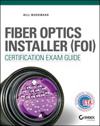
Some of the largest cables, used for telephone transmissions, can be several inches in diameter and contain hundreds of wires, as shown in Figure 7.1. These cables are very heavy, difficult to bend, and expensive.
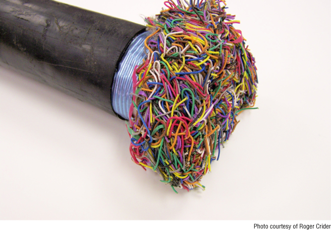
Figure 7.1 Cable with hundreds of wires
Fiber-optic cables like the one shown in Figure 7.2 do not need to be as large as the cable shown in Figure 7.1 because the bandwidth of an optical fiber over a long distance is many times greater than the bandwidth of a wire. Greater bandwidth means fewer optical fibers are required to carry the same information the larger cable is carrying. This results in a small, low-cost fiber-optic cable that is much easier to handle and terminate than the cable shown in Figure 7.1. Chapter 13, “Fiber-Optic System Advantages,” compares the performance of fiber-optic and copper cables.

Figure 7.2 Typical fiber-optic cable
Optical fibers are used in many different configurations and environments; manufacturers have created a wide variety of cable types to meet the needs of almost any application. The type of signal being carried and the number of optical fibers required are just two of the many considerations when selecting the right cable for an application. Other factors include the following:
- Tensile strength
- Temperature range
- Bend radius
- Flammability
- Buffer type
- Structure type
- Jacket type
- Weight
- Armor
- Crush resistance
The exact combination of these factors varies, depending on the application and operational environment. A cable installed inside an office building, for example, will be subject to less extreme temperatures than one installed outdoors or in an aircraft. Cabling installed in a manufacturing facility may be exposed to abrasive dusts, corrosive chemicals, or hotwork, such as welding, requiring special protection. Some cables may be buried underground, where they are exposed to burrowing or chewing animals, whereas others may be suspended between poles, subject to their own weight plus the weight of animals and birds who think the cables were put there for them.
Cable Components
Whether a cable contains a single optical fiber, several optical fibers, or hundreds of optical fibers, it has a basic structure in common with other cables. As shown in Figure 7.3, a typical fiber-optic cable consists of the optical fiber (made up of the core, cladding, and coating), a buffer, a strength member, and an outer protective jacket or sheath. Let's look at these components individually.

Figure 7.3 Fiber-optic cable components
Buffer
As you learned in Chapter 4, “Optical Fiber Construction and Theory,” all optical fiber has a coating. The coating is the optical fiber's first protective layer. The protective layer placed around the coating is called the buffer. There are two buffer types: loose buffer and tight buffer.
Loose Buffer
Loose buffer is also referred to as loose tube buffer or loose buffer tube. A loose buffer consists of a buffer layer or tube that has an inner diameter much larger than the diameter of the coated optical fiber, as shown in Figure 7.4.
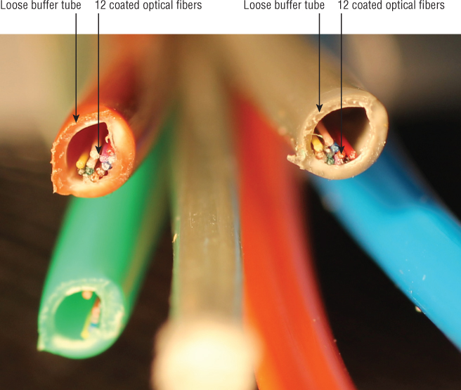
Figure 7.4 Loose-buffered cable has a buffer diameter greater than the fiber diameter.
The loose buffer provides room for additional optical fiber when the cable is manufactured. This extra room also allows the optical fiber to move independently of the buffer and the rest of the cable components. This is an important factor when the cable is subjected to temperature extremes. A variety of materials are used to make up a fiber-optic cable. These materials may not expand or contract the same way as the optical fiber during temperature changes. The additional fiber in the loose buffer will allow the cable to expand (increase in length) or contract (decrease in length) without placing tensile forces on the optical fiber.
Loose-buffered cable may be single-fiber or multifiber (not to be confused with single-mode and multimode fiber), meaning that it may have one or many optical fibers running through each buffer tube. In addition, a cable may contain a number of loose buffers grouped together, as shown in Figure 7.5. In such cables, loose-buffered tubes are grouped around a central core that provides added tensile strength and a resistance to bending.

Figure 7.5 Loose-buffered tubes in a cable
Loose-buffered cables are designed for indoor and outdoor applications. For outdoor applications, the buffer tubes may be filled with a gel. The gel displaces or blocks water and prevents it from penetrating or getting into the cable. A gel-filled loose-buffered cable is typically referred to as a loose tube, gel-filled (LTGF) cable.
Fully waterblocked gel-free loose-tube cables are an alternative to gel-filled cables. A gel-free cable replaces the gel with a water-swellable tape. When the water-swellable tape makes contact with water, it quickly turns into a gel and swells. The swelling tape fills up the free space within the cable and blocks the water protecting the cable against damage from water ingress.
Loose-buffered cables are ideal for direct burial and aerial installations. They are also very popular for indoor/outdoor applications.
Tight Buffer
Tight-buffered cable is typically used in more controlled environments where the cable is not subjected to extreme temperatures or water. In short, tight-buffered cable is generally used for indoor applications rather than outdoor applications.
As shown in Figure 7.6, tight-buffered cable begins with a 250μm coated optical fiber. The buffer is typically 900μm in diameter and is applied directly to the outer coating layer of the optical fiber. In this way, it resembles a conventional insulated copper wire. The buffer may have additional strength members running around it for greater resistance to stretching.
Figure 7.6 Tight-buffered cable uses a buffer attached to the fiber coating.
One of the benefits of tight-buffered cable is that the buffered optical fiber can be run outside of the larger cable assembly for short distances, as shown in Figure 7.7. This makes it easier to attach connectors. The standard diameter of the buffer allows many different types of connectors to be applied.

Figure 7.7 Tight-buffered optical fibers extending out of the cable assembly
Tight-buffered cables have some advantages over loose-buffered cables. Tight-buffered cables are generally smaller in diameter than comparable loose-buffered cables. The minimum bend radius of a tight-buffered cable is typically smaller than a comparable loose-buffered cable. These two advantages make tight-buffered cable the choice for indoor installations where the cable is routed through walls and other areas requiring tight bends.
Strength Members
You've already learned a bit about how strength members help increase a cable's tensile strength. The primary importance of these members is to ensure that no tensile stress is ever placed on the optical fiber. The installation of a fiber-optic cable may require a great deal of pulling, which places considerable tensile stress on the strength members. The strength members need to be able to support the installation tensile stresses and the operational tensile stresses.
Strength members may run through the center of a fiber-optic cable, or they may surround the buffers just underneath the jacket. Combinations of strength members may also be used depending on the application and the stress the cable is designed to endure. Some of the most common types of strength members are made of
- Aramid yarns, usually Kevlar™
- Fiberglass rods
- Steel
Aramid yarns, as shown in Figure 7.8, are useful when the entire cable must be flexible. These fine, yellowish or gold yarns are made of the same material used in high-performance sails, bulletproof vests, and fire protection gear. They have the advantages of being light, flexible, and quite strong. Aramid yarns may be used in cable subgroups if they will be bundled into larger cables.
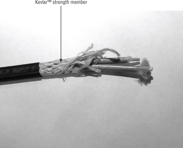
Figure 7.8 Aramid (Kevlar) yarns used as strength members
Larger cables and most loose-buffered cables typically have a central member of either fiberglass or steel added, as shown in Figure 7.9. This central member provides tensile strength and a resistance to bending. This resistance to bending prevents the cable from being over-bent and kinking the loose-buffered tubes.
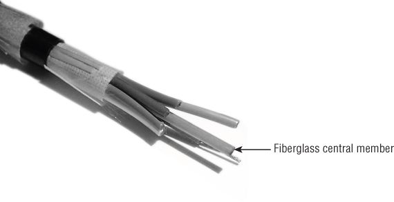
Figure 7.9 A fiberglass central member adds tensile strength and a resistance to bending.
Although the tensile strength of steel is greater than the tensile strength of fiberglass, many applications require a dielectric, or nonconductive cable. Fiberglass is nonconductive whereas steel is not. Steel running through a cable outdoors makes an excellent lightning rod.
Jacket
The jacket is the cable's outer protective layer. It protects the internal components from the outside world. The jacket may be subject to many factors such as sunlight, ice, animals, equipment accidents, and ham-handed installers. The jacket must also provide protection from abrasion, oil, corrosives, solvents, and other chemicals that could destroy the components in the cable.
Jacket materials vary depending on the application. Typical jacket materials include
- Polyvinyl chloride (PVC) PVC is used primarily for indoor cable runs. It is fire retardant and flexible, and it's available in different grades to meet different conditions. PVC is water resistant; however, PVC does not stand up well to solvents. In addition, it loses much of its flexibility at low temperatures.
- Polyethylene This material is typically used outdoors. It offers excellent weather and sun resistance in addition to excellent water resistance and flexibility in low temperatures. Specially formulated polyethylene offers low-smoke, zero-halogen performance.
- Polyvinyl difluoride (PVDF) This material is chosen for its low-smoke and fire-retardant properties for use in cables that run through airways or plenums in a building. PVDF cables are not as flexible as other types, so their fire safety properties are their primary draw.
- Polytetrafluoroethylene (PTFE) This material is primarily used in aerospace fiber-optic cables. It has an extremely low coefficient of friction and can be used in environments where temperatures reach as high as 260° C.
Some cables contain multiple jackets and strength members, as shown in Figure 7.10. In such cables, the outermost jacket may be referred to as the sheath; the inner protective layers are still called jackets.

Figure 7.10 The sheath is the outer layer of a cable with multiple jackets.
The ripcord is a piece of strong thread running through the cable just under the jacket or sheath as shown in Figure 7.11. When the ripcord is pulled, it splits the jacket easily to allow the fibers to be separated for connectorization or splicing. The ripcord reduces the risk incurred when cutters or knives are used to split the jacket. The ripcord will not penetrate the jackets of the individual simplex cables as a cutter or knife may when the blade depth is not accurately controlled.
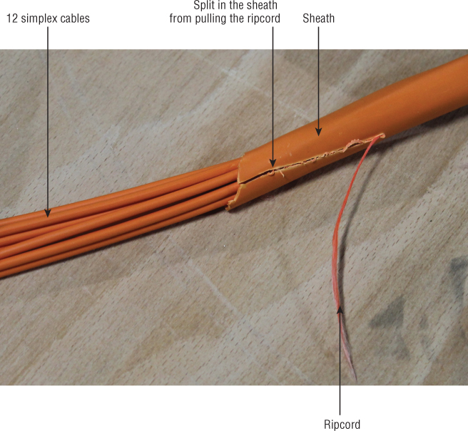
Figure 7.11 The ripcord splitting the cable sheath
Cable Types
As uses for optical fiber have become more varied, manufacturers have begun producing cables to meet specific needs. Cable configurations vary based on the type of use, the location, and future expansion needs, and it is likely that more will be created as future applications emerge.
Bear in mind that different cable arrangements are variations on a theme. Different combinations of buffer type, strength members, and jackets can be used to create cables to meet the needs of a wide variety of industries and users.
Let's look at some of the commonly available optical fiber cables.
Cordage
The simplest types of cables are called cordage and are used in connections to equipment and patch panels. They are typically made into patch cords or jumpers. The major difference between cordage and cables is that cordage has only one optical fiber/buffer combination in a jacket, whereas cables may have multiple optical fibers inside a jacket or sheath.
The two common types of cordage are simplex and duplex.
Simplex Cordage
Simplex cordage, shown in Figure 7.12, consists of a single optical fiber with a tight buffer, an aramid yarn strength member, and a jacket.
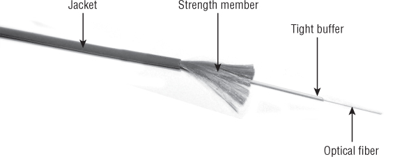
Figure 7.12 Simplex cordage
Simplex cordage gets its name from the fact that, because it is a single fiber, it is typically used for one-way, or simplex, transmission, although bidirectional communications are possible using a single fiber.
Duplex Cordage
Duplex cordage, also known as zipcord, is similar in appearance to household electrical cords, as you can see in Figure 7.13. Duplex cordage is a convenient way to combine two simplex cords to achieve duplex, or two-way, transmissions without individual cords getting tangled or switched around accidentally.

Figure 7.13 Duplex cordage
Distribution Cable
When it is necessary to run a large number of optical fibers through a building, distribution cable is often used. Distribution cable consists of multiple tight-buffered fibers bundled in a jacket with a strength member. These cables, like the one shown in Figure 7.14, may also feature a dielectric central member to increase tensile strength, resist bending, and prevent the cable from being kinked during installation.
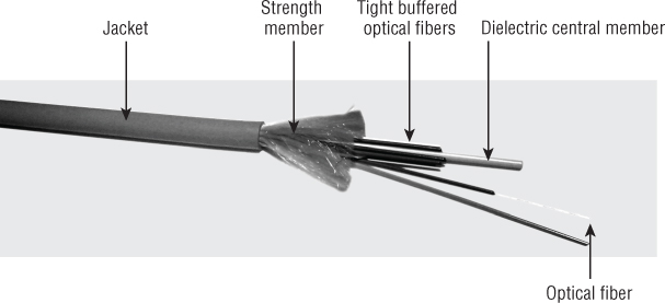
Figure 7.14 Distribution cable with dielectric central member
Distribution cables are ideal for inter-building routing. Depending on the jacket type they may be routed through plenum areas or riser shafts to telecommunications rooms, wiring closets, and workstations. The tight-buffered optical fibers are not meant to be handled much beyond the initial installation, because they do not have a strength member and jacket.
Distribution cables may carry up to 144 individual tight-buffered optical fibers, many of which may not be used immediately but allow for future expansion.
Breakout Cable
Breakout cables are used to carry optical fibers that will have direct termination to the equipment, rather than being connected to a patch panel.
Breakout cables consist of two or more simplex cables bundled with a strength member and/or central member covered with an outer sheath, as shown in Figure 7.15. These cables are ideal for routing in exposed trays or any application requiring an extra rugged cable that can be directly connected to the equipment.

Figure 7.15 Breakout cable containing simplex cables bundled with a central strength member
Armored Cable
Armored cable can be used for indoor applications and outdoor applications. An armored cable typically has two jackets. The inner jacket is surrounded by the armor and the outer jacket or sheath surrounds the armor.
An armored cable used for outdoor applications, shown in Figure 7.16, is typically a loose tube construction designed for direct burial applications. The armor is generally a corrugated aluminum tape surrounded by an outer polyethylene jacket. This combination of outer jacket and armor protects the optical fibers from gnawing animals and the damage that can occur during direct burial installations.

Figure 7.16 Armored cable for outdoor applications
Armored cable used for indoor applications may feature tight-buffered or loose-buffered optical fibers, strength member(s), and an inner jacket. The inner jacket is commonly surrounded by a spirally wrapped interlocking metal tape armor. This type of armor, shown in Figure 7.17, is rugged and provides crush resistance. These cables are used in heavy traffic areas and installations that require extra protection, including protection from rodents.
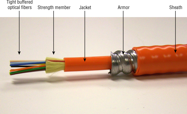
Figure 7.17 Armored cable for indoor applications
Messenger Cable
When a fiber-optic cable must be suspended between two poles or other structures, the strength members alone are typically not enough to support the weight of the cable and any additional forces that may be placed on the cable. For aerial installations a messenger wire is required. The messenger wire can be external to the fiber-optic cable or integrated into the cable.
When the messenger wire is integrated into the fiber-optic cable, the cable is typically referred to as a messenger cable. These cables typically feature a 0.25″ stranded steel messenger wire. The messenger wire, sometimes referred to simply as the messenger, is integrated into the outer jack of the cable, as shown in Figure 7.18.

Figure 7.18 Messenger cable used for aerial installations
Also called figure 8 cable for the appearance of its cross section, messenger cable greatly speeds up an aerial installation because it eliminates the need to lash the fiber-optic cable to a pre-run messenger wire.
If a messenger wire is not incorporated into the cable assembly used, the cable will have to be lashed to messenger wire. A messenger wire is a steel or aluminum wire that supports the fiber-optic cable in an aerial installation. Either way, cables in aerial installations must be able to withstand loading from high winds, ice, birds and climbing animals, and even windblown debris such as branches.
Ribbon Cable
Ribbon cable is a convenient solution for space and weight problems. The cable contains fiber ribbons, which are actually coated optical fibers placed side by side, encapsulated in Mylar tape (see Figure 7.19), similar to a miniature version of wire ribbons used in computer wiring. A single ribbon may contain 4, 8, or 12 optical fibers. These ribbons can be stacked up to 22 high.

Figure 7.19 Ribbon cables consist of parallel fibers held together with Mylar tape.
Because the ribbon contains only coated optical fibers, this type of cable takes up much less space than individually buffered optical fibers. As a result, ribbon cables are denser than any other cable design. They are ideal for applications where limited space is available, such as in an existing conduit that has very little room left for an additional cable.
As shown in Figure 7.20, ribbon cables come in two basic arrangements. In the loose tube ribbon cable, fiber ribbons are stacked on top of one another inside a loose-buffered tube. This type of arrangement can hold several hundred fibers in close quarters. The buffer, strength members, and cable jacket carry any strain while the fiber ribbons move freely inside the buffer tube.

Figure 7.20 Armored loose tube ribbon cable (bottom) and jacketed ribbon cable (top)
The jacketed ribbon cable looks like a regular tight-buffered cable, but it is elongated to contain a fiber ribbon. This type of cable typically features a small amount of strength member and a ripcord to tear through the jacket.
While ribbon fiber provides definite size and weight savings, it does require special equipment and training to take advantage of those benefits. Connectors, strippers, cleavers, and fusion splicers must all be tailored to the ribbon fiber. For these reasons, ribbon fiber may not be the best solution in all situations.
Submarine Cable
Submarine cable is specially designed for carrying optical fiber underwater. Not all submarine cable is the same, however. Depending on the distance it will span and the type of service it will provide, submarine cable can take many different forms.
Submarine cable may be laid in trenches under the bottom of waterways where shipping or fishing activities threaten to snag or damage the cable, or it may be laid directly on the bottom of less-traveled waterways, or on the deep ocean floor where such activities do not penetrate. Figure 7.21 shows a multi-optical-fiber submarine cable with armor and metal strength members.

Figure 7.21 Submarine cable with armor and metal strength members
Aerospace Cable
Aerospace cables are designed to be installed in aircraft and spacecraft. These cables are designed to operate in extreme temperature environments. In addition, they must protect the optical fiber from the shock and vibration associated with aircraft and spacecraft. While the optical fiber used in many aerospace cables may be the same optical fiber used in other cable types, the coating, buffer, and jacket are typically different.
Structure Type
A variety of aerospace fiber-optic cables are available for use in different locations on aircraft or spacecraft. These cables can typically be separated into two structure types: tight and loose. Structure types should not be confused with buffer types. A tight-buffered optical fiber may be used in a loose structure fiber-optic cable.
ARINC Report 802, Fiber Optic Cables defines the construction requirements for loose and tight structure cables for aerospace and avionic applications. A loose structure cable allows limited movement of the buffered fiber (usually 900μm in diameter) with respect to the outer jacket and strength member. A tight structure cable does not allow any movement of the buffered fiber with respect to the outer jacket and strength member.
Applications
In Chapter 1, “History of Fiber Optics and Broadband Access,” you learned that since the turn of the century, fiber optics has helped to increase broadband download speeds by a factor of 5000. Just as the telecommunications industry is incorporating more and more optical fiber, so are the aerospace and avionics industries. The Boeing 787 Dreamliner has 110 fiber-optic links and over 1.7km of fiber-optic cable. The aerospace cable assembly shown in Figure 7.22 is similar to one that could be found on the Dreamliner.
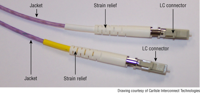
Figure 7.22 Aerospace fiber-optic cable assembly with LC connectors
Aerospace tight or loose structure cables can have a very wide temperature range based on the location where they are installed. Cables designed to be used inside avionics boxes or cabinets typically have a temperature range of –40° C to +85° C. Cables designed to be used between cabinets typically have a temperature range of –65° C to +125° C, whereas those cables used by the engines have a temperature range of –65° C to +260° C.
Cable Components
Figure 7.23 shows the components of a typical aerospace fiber-optic cable. This cable features a primary and secondary buffer. The primary buffer is the coating applied directly over the cladding of the optical fiber. Aerospace cables may use a variety of coatings depending on the temperature range required. A typical acrylate coating has a maximum operating temperature of 100° C whereas some high-temperature acrylates may perform at temperatures up to 125° C. Silicone, carbon, and polyimide coatings have greater temperature ranges than acrylate. Detailed information on optical fiber coatings can be found in Chapter 4.

Figure 7.23 Typical aerospace fiber-optic cable
The secondary buffer shown in Figure 7.24 is polytetrafluoroethylene (PTFE). The bondable layer surrounding the secondary layer is a polyimide tape, and the barrier layer is unsealed PTFE. The strength member is braided Kevlar, and the jacket shown in Figure 7.25 is extruded FEP (fluorinated ethylene propylene). This jacket material has a service temperature range of –100° C to +200° C as well as excellent chemical and UV resistance properties; it is also flame retardant.
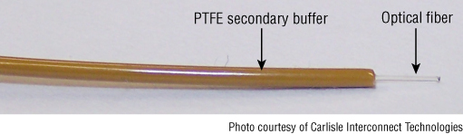
Figure 7.24 PTFE secondary buffer
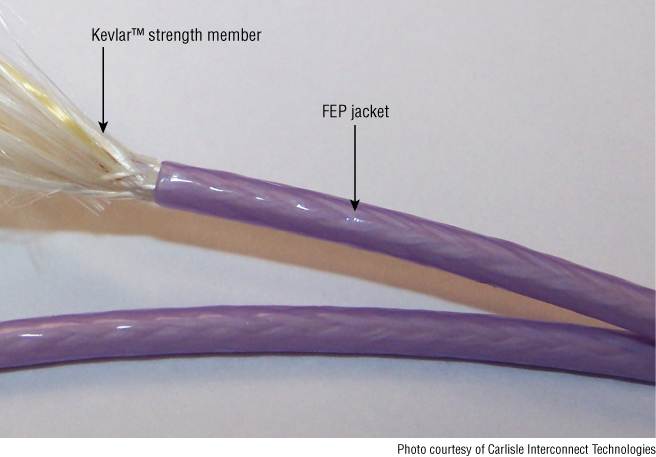
Figure 7.25 FEP jacket and braided Kevlar strength member
Hybrid Cable
Hybrid cable, as applied to fiber optics, combines multimode and single-mode optical fibers in one cable. Hybrid cable should not be confused with composite cable, although the terms have been used interchangeably in the past.
Composite Cable
Composite cable, as defined by the National Electrical Code (NEC), is designed to carry both optical fiber and current-carrying electrical conductors. These cables may also contain non-current-carrying conductive members such as metallic strength members, metallic vapor barriers, metallic armor, or a metallic sheath.
The composite cable shown in Figure 7.26 consists of optical fibers along with twisted-pair wiring typical of telephone wiring. This arrangement is convenient for networks that carry fiber-optic data and conventional telephone wiring to the same user. Composite cable also provides installers with a way to communicate during fiber installation and provides electrical power to remote equipment, such as repeaters, along the fiber's route.
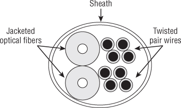
Figure 7.26 Composite cable carries fiber and wiring in the same run.
Cable Duty Specifications
The various combinations of strength members, jacket materials, and fiber arrangements are determined by the specific requirements of an installation. Among the factors considered are the amount of handling a cable will take, the amount of stress the cable must endure in normal use, and the locations where it will run.
Cable duty specifications are typically divided into two basic types:
- Light-duty cables These are designed for basic protection of the fiber within and minimal handling. A good example of a light-duty fiber cable is a simplex cord, which consists of a tight-buffered fiber with a strength member and a jacket. Simplex cordage is not engineered to withstand excessive pulling forces, and the jacket is engineered for flexibility and ease of handling, not harsh environments.
- Heavy-duty cables These are designed for more and rougher handling, with additional strength members and jacketing around the fiber. They are made for harder pulling during installation, and they protect the fiber within from damage in exposed or extreme environments.
Cable Termination Methods
Some fibers, such as those found in simplex and duplex cords and breakout cable, are already set up to receive connectors and can be handled easily. Others, including loose-buffered cables, must be prepared for connectors and handling with special kits.
These kits, known as fanout kits and breakout kits, are designed to adapt groups of coated fibers for connectors by separating them and adding a tight buffer (fanout kit) or a tight buffer, strength member, and jacket (breakout kit) to each one.
Fanout Kit
The fanout kit, shown in Figure 7.27, converts loose-buffered fibers into tight-buffered fibers ready for connectors. A typical fanout kit contains an enclosure sometimes called a furcation unit. The furcation unit attaches to the loose-buffer tube. Hollow tight-buffer tubes 900μm in diameter are applied over the optical fibers and passed into the furcation unit, which is then closed, locking the tight buffers in place on the fibers. After the fibers have the buffers applied, connectors can be attached for use in a patch panel or other protected enclosure.
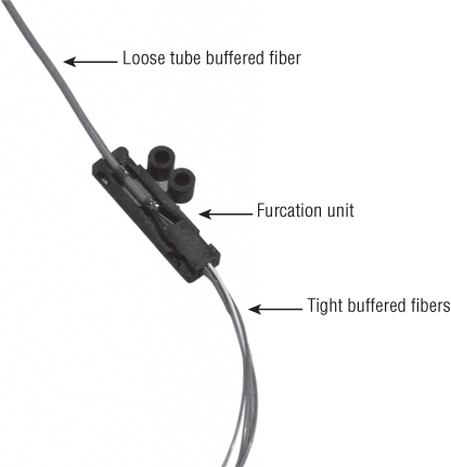
Figure 7.27 A fanout kit adds a tight buffer to individual fibers.
Breakout Kit
The breakout kit, shown in Figure 7.28, is similar to the fanout kit in that it spreads the fibers from the loose-buffer tube through a furcation kit and provides 900μm tight buffers to be applied over the optical fiber. The breakout kit, however, is designed to allow the optical fiber to be connected directly to equipment with standard connectors.
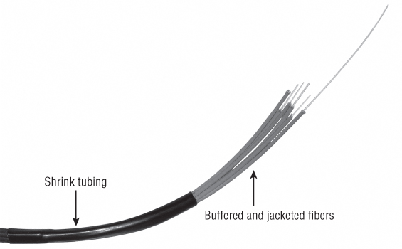
Figure 7.28 A breakout kit adds a tight buffer, strength member, and a jacket to individual optical fibers.
In addition to buffer material, the breakout kit provides a 3mm diameter jacket with an aramid strength member that slips over the optical fiber. Heat-shrink tubing and epoxy is used to join the individual jackets to the cable.
Breakout kits and fanout kits are available to match the number of fibers in the cable being used, and some companies offer kits that can be used with ribbon cable. Different length buffer tubes are available for fanout kits.
Note that different vendors may use a variety of terms or trade names to refer to breakout kits and fanout kits.
Blown Fiber
What if you knew that you wanted to run fiber in a building, but you didn't know exactly what equipment it would be serving or what the requirements for the fiber were? One solution to this dilemma is blown fiber.
Blown fiber installation starts with a hollow tube about 5mm in diameter. This tube is installed just like a cable and acts as a loose tube buffer for fibers that will run through it later. The tube may also be part of a cable assembly, which may carry up to 19 tubes and is available in configurations similar to other cables, including armored, all-dielectric, plenum, and riser.
To run the fibers through the tube, you simply lead the fibers into one end of the tube and blow pressurized air through the tube. The air carries the fibers with it through the tube, similar to the way that pneumatic carriers at drive-through tellers shoot your deposits into the bank building.
Blown fiber can be used, as already described, when the fiber needs in a building are not yet known or when fiber needs to be repaired or upgraded. Blown fiber is also useful when a company cannot afford to install all of the fiber that it might potentially use. As a business grows and the new fiber can be economically justified, it can be blown in as needed.
One advantage of blown fiber, even when it is installed all at once, is that cuts or damaged sections can be repaired quickly. In case of an accidental cut from power equipment, for example, the damaged section can be cut out, a new section spliced in, and new fiber blown in. This can be a great time-savings over splicing multiple broken fibers in a cable. Blown fiber can be run 1000' or more through a building, around curves, and uphill, in a very short time.
Blown fiber is covered in detail in Chapter 12, “Cable Installation and Hardware.”
NEC Provisions for Fiber-Optic Cables and Raceways
The National Electrical Code (NEC) is published by the National Fire Protection Association (NFPA) and contains provisions that are considered necessary for safety. NEC Article 90 states that the purpose of the code is the practical safeguarding of persons and property from hazards arising from the use of electricity. It also states that the NEC is not intended as a design specification or an instruction manual for untrained persons. Local and state governments typically adopt it, making compliance mandatory.
It provides specific guidance for running fiber-optic cable within buildings. The NEC requires cables to be tested for fire resistance and smoke characteristics, establishes which types of cables may be run in different areas of a building, and specifies the types of raceways that can be used.
Be sure you stay current with the latest NEC provisions. The NEC is updated every 3 years. The information in this chapter can be found in NEC Article 770, “Optical Fiber Cables and Raceways.” To ensure this chapter contains the latest information, the 2014 NEC was used for the updates.
Like the industry standards, Article 770 in the NEC has increased in page count since the turn of the century. It required approximately five pages in the 1999 NEC. That page count doubled in the 2014 NEC.
NEC Fiber-Optic Cable Types
The NEC recognizes three types of fiber-optic cables in Article 770:
- Nonconductive Cables containing no electrically conductive materials.
- Conductive Cables containing non-current-carrying conductive members, including strength members, armor, or sheath.
- Composite Cables containing optical fiber and current-carrying electrical conductors. These cables may also contain non-current-carrying conductive members such as metallic strength members, metallic vapor barriers, metallic armor, or a metallic sheath.
Listed and Nonlisted
The NEC classifies fiber-optic cables according to their electrical and fire safety characteristics and contains rules for the use of each cable type to minimize hazards. Any fiber-optic cabling run indoors must be listed as suitable for the purpose. Any outside plant nonlisted fiber-optic cabling that is brought into a structure must be terminated after no more than 15m or 50' and connectorized or spliced to a listed cable.
A listed fiber-optic cable has had its performance verified by Underwriters Laboratory (UL). The outer surface of the cable or a marker tape should be clearly marked at intervals not to exceed 40″ with the following information:
- Cable type-letter designation such as OFN, OFC, OFNR, OFNP, etc.
- Manufacturer's identification
- UL symbol or the letters “UL”
Optical fiber cables installed within buildings shall be listed as being resistant to the spread of fire. Three listed types of cables are recognized in Article 770 for indoor installations: plenum cable, riser cable, and general-purpose cable.
Plenum Cable
Plenum cables, whether conductive or nonconductive, are suitable for use in ducts, plenums, and other spaces used for environmental air. These cables will have fire resistance and low smoke-producing characteristics.
Riser Cable
Riser cables, whether conductive or nonconductive, are suitable for a vertical run in a shaft or from floor to floor. These cables will have fire-resistance characteristics capable of preventing the carrying of a fire from floor to floor.
General-Purpose Cable
General-purpose cables, whether conductive or nonconductive, are resistant to the spread of fire. However, these cables are not suitable for plenum or riser applications.
Table 7.1 shows the cable types along with the markings each cable will contain. Markings should be clearly visible on the cable, as shown in Figure 7.29, and no cable should be used indoors unless it listed and contains the NEC cable type marking on it.
Table 7.1 NEC cable types and description
| Marking | Type | Location | Permitted substitutions |
| OFNP | Nonconductive optical fiber plenum cable | Ducts, plenums, other air spaces | None |
| OFCP | Conductive optical fiber plenum cable | Ducts, plenums, other air spaces | OFNP |
| OFNR | Nonconductive optical fiber riser cable | Risers, vertical runs | OFNP |
| OFCR | Conductive optical fiber riser cable | Risers, vertical runs | OFNP, OFCP, OFNR |
| OFNG | Nonconductive optical fiber general-purpose cable | General-purpose use except for risers and plenums | OFNP, OFNR |
| OFCG | Conductive optical fiber general-purpose cable | General-purpose use except for risers and plenums | OFNP, OFCP, OFNR, OFCR, OFNG, OFN |
| OFN | Nonconductive optical fiber general-purpose cable | General-purpose use except for risers, plenums | OFNP, OFNR |
| OFC | Conductive optical fiber general-purpose cable | General-purpose use except for risers, plenums | OFNP, OFCP, OFNR, OFCR, OFNG, OFN |

Figure 7.29 NEC cable type marking
All indoor cables must be resistant to the spread of fire, and those listed as suitable for environmental air spaces such as plenums must also have low smoke-producing characteristics. Note in the substitutions list that nonconductive cables may always be substituted for conductive cables of an equal or lower rating, but conductive cables may never be substituted for nonconductive cables. Figure 7.30 shows the order in which cables may be substituted for one another.

Figure 7.30 NEC cable substitution guide
The NEC also describes the raceways and cable trays that can be used with fiber-optic cables and the conditions under which each type of cable may be used. This information is covered in Chapter 12.
Cable Markings and Codes
In addition to the NEC cable marking, optical fiber cables typically have a number of other markings and codes. Markings that appear on the jacket of the cable help identify what is inside the cable and where it originated. They may also include aids for measuring the cable length.
Inside the cable, the fiber buffers are usually color-coded with standard colors to make connections and splices easier. However, some manufacturers use numbers instead of colors.
External Markings
A cable's external markings typically consist of the manufacturer's information, including the manufacturer's name and phone number, cable part number or catalog number, the date the cable was manufactured, and occasionally the industry standards the optical fiber complies to. Information about the cable itself includes the NEC cable marking, the fiber type (multimode/single-mode or core/cladding size), and sequential cable length markings in meters or feet.
Date, Industry Standards, and Fiber Type
The date the cable was manufactured can be very helpful in determining the performance standards of the optical fiber within the cable. As you learned in Chapter 5, “Optical Fiber Characteristics,” there have been significant changes in the performance of multimode optical fiber since the turn of the century. The cable shown in Figure 7.31 was manufactured at the turn of the century. In addition, the cable markings identify three standards that define the optical and geometrical performance of the optical fiber. These standards are
- Bellcore GR-409-CORE
- ISO/IEC 11801
- TIA/EIA-568-A

Figure 7.31 Duplex cordage manufactured in June 2000
The cable shown in Figure 7.31 was manufactured in June 2000. Optical Fiber Cabling Component Standard TIA/EIA-568-B.3 superseded the Commercial Building Telecommunications LAN/WAN Cabling Standard TIA/EIA-568-A in April 2000. This is an example of cable being manufactured with optical fiber that did not comply with the latest published standards. As it has been mentioned before in this book, when a standard changes, old cable is not ripped out and replaced with new. A cable manufacturer with reels of TIA/EIA-568-A optical fiber on the shelf is not going to waste that inventory just because a standard changed.
The cable shown in Figure 7.32 was manufactured in May 2008. There are no standards markings on this cable, so determining the industry standard(s) that define the optical and geometrical performance of the optical fibers in this cable is not as straightforward as with the cable in Figure 7.31. However, there is a clue: the word “laser” is printed on the jacket. This implies that the optical fiber was optimized for a laser light source. The 50μm optical fiber core size is also printed on the jacket. Combining both pieces of data indicates that the optical fiber in the cable is OM3.
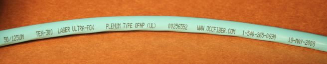
Figure 7.32 Laser-optimized 6-fiber breakout cable manufactured in May 2008
OM3 optical fiber cannot be found in TIA/EIA-568-B.3. However, it can be found in ANSI/TIA-568-C.3, which was published June 2008, one month after the cable shown in Figure 7.31 was manufactured. This is an example of a cable that contains an optical fiber that exceeds the transmission performance parameters of a current published standard. As mentioned previously in this book, standards define a minimum level of performance and many manufacturers offer products that exceed the minimum performance levels. Oftentimes the working groups within standards organizations are playing catch-up, creating standards for products that currently exist and may have been in widespread use for several years or more.
Remember, you can always contact the cable manufacturer using the phone number printed on the cable to determine the optical and geometrical performance of the optical fiber.
Color Codes
As with copper wiring, optical fibers running in cables must have some way of being distinguished from one another so that they can be connected properly at each end. TIA-598-C provides color-coding schemes for premises jackets and optical fibers within a fiber-optic cable. Table 7.2 shows the color-coding scheme for individual fibers bundled in a cable.
Table 7.2 -598-C fiber color code
| Fiber number | Base color/tracer | Fiber number | Base color/tracer |
| 1 | Blue | 19 | Red/Black |
| 2 | Orange | 20 | Black/Yellow |
| 3 | Green | 21 | Yellow/Black |
| 4 | Brown | 22 | Violet/Black |
| 5 | Slate | 23 | Rose/Black |
| 6 | White | 24 | Aqua/Black |
| 7 | Red | 25 | Blue/Double Black |
| 8 | Black | 26 | Orange/Double Black |
| 9 | Yellow | 27 | Green/Double Black |
| 10 | Violet | 28 | Brown/Double Black |
| 11 | Rose | 29 | Slate/Double Black |
| 12 | Aqua | 30 | White/Double Black |
| 13 | Blue/Black | 31 | Red/Double Black |
| 14 | Orange/Black | 32 | Black/Double Yellow |
| 15 | Green/Black | 33 | Yellow/Double Black |
| 16 | Brown/Black | 34 | Violet/Double Black |
| 17 | Slate/Black | 35 | Rose/Double Black |
| 18 | White/Black | 36 | Aqua/Double Black |
Table 7.3 shows the color coding used on premises cable jackets to indicate the type of fiber they contain, if that is the only type of fiber they contain.
Table 7.3 TIA-598-C premises cable jacket colors
| Fiber type | Jacket color for nonmilitary applications | Jacket color for military applications |
| Multimode (50/125μm) | Orange | Orange |
| Multimode (50/125μm) Laser-optimized | Aqua | |
| Multimode (62.5/125μm) | Orange | Slate |
| Multimode (100/140μm) | Orange | Green |
| Single-mode (NZDS) | Yellow | Yellow |
| Polarized maintaining Single-mode | Blue |
Cable Numbers
The color-coding schemes for premises jackets and optical fibers within a fiber-optic cable described in TIA-598-C are not always used. For example, the jacket colors of every simplex cable shown in Figure 7.33 are the same. You can identify a specific simplex cable by locating the number that is printed on the jacket. The simplex cable number is printed every 6″ along the entire length of the cable.
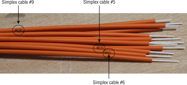
Figure 7.33 Breakout cable with 12-simplex cables, each with printed cable numbers
With all numbering or coloring schemes, there are advantages and disadvantages. In an area that is not lit well, it can be difficult to correctly identify colors. In addition, how well color differences are perceived can vary from person to person. Numbering eliminates color perception problems.
Sequential Markings
A cable's external markings may include sequential markings, as shown in Figure 7.34. Sequential markings are numbers that appear every 2' or 1m. These markings are useful in determining how much cable is left on a reel, measuring off large runs of cable, or simply determining the length of a piece of cable without pulling out a tape measure.

Figure 7.34 Sequential marking in feet on a fiber-optic cable
The numbers themselves indicate cable length, not optical-fiber length. To measure the length of the cable using the sequential markings, first determine the measurement standard that is being used. Next, subtract the number at the low end from the number at the high end. The difference between the two is the length.
Because some measurements dealing with fiber optics use meters rather than feet, you may need to convert any measurements in feet to the metric system. The formula for converting length is
- 1 foot = 0.3048 meter
Let's practice measuring out a length of cable using sequential markings. To find the length in meters of a cable that has sequential markings of 846 at one end and 2218 at the other end, and the markings are measuring the cable in feet, you first determine the distance between the markings using this formula:
- 2218 – 846 = 1372 feet
Now, convert feet to meters:
- 1372 × 0.3048 = 418.2 meters
Remember that the length of the cable is not necessarily the length of the optical fiber inside of it. In loose tube cable, the fiber is actually slightly longer than the cable. This fact becomes important if fault location procedures tell you that there is a fault at a specific distance from the end of the fiber. That distance could be short of the measured distance on the outside of the cable since the fiber wanders inside of the buffer tube.
Bend Radius Specifications
Throughout the installation process, optical fiber's light-carrying abilities are threatened by poor handling, damage from tools or accidents, and improper installation procedures.
One of the installation hazards that can cause attenuation or damage to the optical fiber is extreme bending. When an optical fiber is bent too far, the light inside no longer reflects off the boundary between the core and the cladding, but passes through to the coating.
To reduce the risk of excessive bending during installation, manufacturers specify a minimum installation and operational bend radius for their optical fiber cables. Following the manufacturer's guidelines reduces the risk of damage to the cable and optical fiber during and after installation. Chapter 12 provides detailed information on cable bend radius.
Summary
This chapter covered the types of cables used to carry optical fibers while protecting them and keeping large numbers of fibers bundled together. It described the materials used in common cables and the different types of cables used to meet different needs.
The chapter described the ways in which fiber can be arranged within cables, along with the methods used to protect the fibers from stretching, damage, and excessive handling. It also described some of the locations in which cables commonly run.
Finally, the chapter discussed NEC fiber-optic cable types and classifications. It described the different types of cable markings and color codes. It also explained how to use sequential markings and where to find cable bend radius information.
Exam Essentials
- Understand optical fiber cable construction. Make sure that you understand the basic components of a fiber optic cable. Be able to describe the materials commonly used in fiber optic cables. Be able to explain the differences between some types of cable components.
- Describe the types of fiber optic cables. Be able to describe the different types of fiber optic cables. Be able to explain how different types of fiber optic cables are used. Be familiar with the advantages and drawbacks of different types of cable.
- Know the NEC cable types and listing requirements. Make sure you know the NEC fiber-optic cable types and classifications. Be able to explain the difference between a listed and nonlisted cable. Be familiar with the NEC cable substitution guide.
- Describe typical cable jack markings. Be able to list the external markings typically found on the jacket of a fiber-optic cable.
- Know the color-coding and numbering schemes. Make sure that you know the TIA-598-C color-coding schemes for premises jackets and optical fibers within a fiber-optic cable.
- Understand sequential markings. Be able to explain how sequential markings are used to determine how much cable is left on a reel, measure off large runs of cable, or simply determine the length of a piece of cable without pulling out a tape measure.
Review Questions
- Which of the following describes the four components of a fiber optic cable?
A. Core, cladding, coating, buffer
B. Optical fiber, buffer, strength member, jacket
C. Core, buffer, jacket, coating
D. Optical fiber, buffer, strength member, coating
Hint: The outer layer protects the internal components from the outside world.
- A buffer tube that has an inner diameter much larger than the diameter of the coated optical fiber is called a
A. Loose buffer
B. Tight buffer
C. Coating
D. Tensile buffer
Hint: Sometimes it is filled with gel.
- One benefit of tight-buffered fiber is that it
A. Has greater tensile strength
B. Has less attenuation
C. Can run for short distances outside the cable
D. Carries a signal farther
Hint: The standard diameter of the buffer allows many different types of connectors to be applied.
- Aramid yarn is used as a strength member because it is
A. Flexible, light, and strong
B. Rigid, heavy, and strong
C. Conductive
D. Only used in combination with fiberglass rods
Hint: It is also sold under the trade name Kevlar.
- The outer protective layer of a fiber-optic cable is called the
A. Coating
B. Buffer
C. Jacket
D. Ripcord
Hint: It may be referred to as the sheath.
- Duplex cordage is convenient for applications that require
A. One-way transmission
B. Two-way transmission
C. Electrical power
D. Two transmission speeds
Hint: It combines two simplex cords.
- Breakout cables contain
A. Two or more individual tight-buffered fibers
B. Two or more loose buffer tubes
C. Two or more simplex cables
D. A mix of loose buffer and tight-buffered fibers
Hint: Each optical fiber has a jacket.
- Distribution cables contain
A. Two or more individual tight-buffered fibers
B. Two or more loose buffer tubes
C. Two or more simplex cables
D. A mix of loose buffer and tight-buffered fibers
Hint: There is only a single jacket.
- An armored cable protects the optical fibers from
A. Temperature changes
B. Sunlight
C. Gnawing animals
D. Magnetic fields
Hint: It also protects the optical fibers from damage that can occur during direct burial installations.
- A messenger cable would typically be
A. Suspended between two poles or other structures
B. Laid in trenches next to the road
C. Laid in trenches under the bottom of waterways
D. Installed in aircraft and spacecraft
Hint: Also called a figure 8 cable
- Hybrid cable as applied to fiber optics combines
A. Loose and tight buffers
B. Single-mode and multimode optical fibers
C. Optical fibers and current-carrying electrical conductors
D. Plastic and glass optical fibers
Hint: It should not be confused with composite cable.
- Composite cable, as defined by the NEC, is designed to carry
A. Optical fiber and conductive strength members
B. Single-mode and multimode optical fibers
C. Optical fibers and current-carrying electrical conductors
D. Plastic and glass optical fibers
Hint: They can provide installers with a way to communicate during installation.
- A __________________ converts loose-buffered fibers into tight-buffered fibers.
A. Breakout kit
B. Buffer kit
C. Coating kit
D. Fanout kit
Hint: Typically contains a furcation unit.
- Which type of NEC recognized fiber-optic cable contains non-current-carrying conductive members?
A. Nonconductive
B. Conductive
C. Composite
D. Hybrid
Hint: It may also have armor.
- Which type of NEC listed fiber-optic cable is suitable for use in ducts and other spaces used for environmental air?
A. Plenum
B. Riser
C. General-purpose
D. Hybrid
Hint: These cables have low smoke-producing characteristics.
- Which NEC marking describes a nonconductive general-purpose fiber-optic cable?
A. OFCG
B. OFNP
C. OFCR
D. OFN
Hint: It has two possible markings.
- Which of the following can be substituted for a cable marked “OFN”?
A. OFC
B. OFCP
C. OFNP
D. OFCR
Hint: It must be the same NEC listed cable type.
- What is the jacket color of laser-optimized simplex cordage?
A. Orange
B. Slate
C. Blue
D. Aqua
Hint: There is no TIA-598-C jacket color for military applications.
- Color-coding schemes for optical fibers within a fiber-optic cable are sometimes replaced by ___________________.
A. Sequential markings
B. Numbers
C. Letters
D. Symbols
Hint: It is printed every 6″.
- ____________________ are useful in determining how much cable is left on a reel.
A. Color codes
B. Cable numbers
C. Sequential markings
D. NEC listing
Hint: They appear every 2' or 1m.
Chapter Exercises
Determine the Cable Type from the NEC Markings
Article 770 of the NEC states that optical fiber cables installed within buildings shall be listed as being resistant to the spread of fire. These cables are also required to be marked.
You have been asked to install the two cables shown later in a riser space. From the markings on the cables, determine the cable types and determine if each cable can be installed in a riser space.

The cable marked OFNR is a nonconductive riser cable and the cable marked OFNP is a nonconductive plenum cable. Per the NEC cable substitution guide in Figure 7.30, both cables can be installed in a riser space. However, only the cable marked OFNP can be installed in the plenum space.
Identify the Fiber Number from the Color Code
TIA-598-C defines a color code for optical fibers within a cable assembly.
You have been asked to identify the fourth and seventh tight-buffered optical fibers in the 12-fiber cable shown here. There are no numbers on the tight buffers; however, each buffer is colored as defined in TIA-598-C. What are the colors of the fourth and seventh tight-buffered optical fibers?
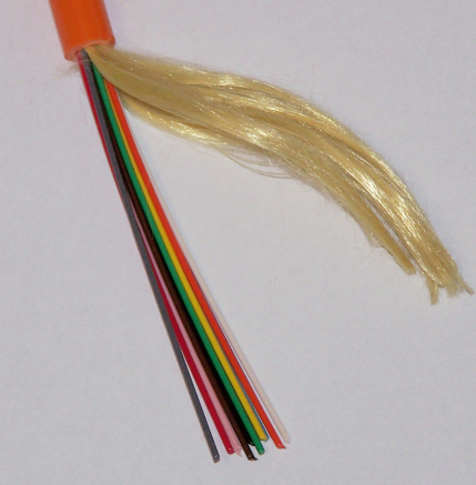
Table 7.2 lists the optical fiber color codes as defined in TIA-598-C. The color for fiber number 4 is brown and the color for fiber number 7 is red.
Determine the Fiber Number from the Cable Markings
The color-coding schemes for premises jackets and optical fibers within a fiber-optic cable described in TIA-598-C are not always used.
You have been asked to identify simplex cable number nine in the 12-fiber cable shown here. Describe the location of that cable.

Simplex cable number 9 is located in the upper-left corner.
Identify the Optical Fiber Type from the Color Code
Premises cable jacket colors are defined in TIA-598-C.
It is your first day on the job and your supervisor has asked you to get some laser-optimized multimode optical fiber from the back of the van. The van contains several different cables, each with a different jacket color. What is the jacket color of the laser-optimized cable?
Table 7.3 list the premises jacket colors as defined in TIA-598-C. The color for the laser-optimized cable is aqua.
Determine the Optical Fiber Type from the Cable Markings
Premises cable jacket colors are defined in TIA-598-C. However installed cables may not comply with revision C of this standard.
You have been asked to identify the optical fiber type in the cable shown here. The jacket color is slate and this cable was not intended for military applications. What type of optical fiber is used in this cable?
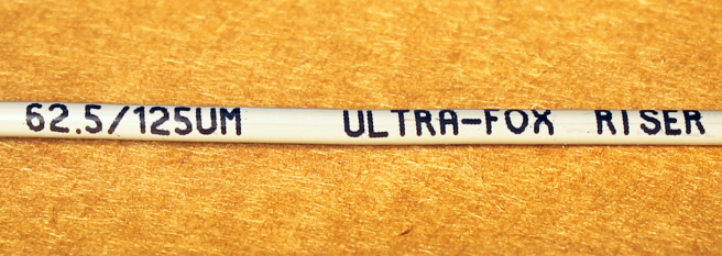
This cable was manufactured in 1999, 6 years before TIA-598-C was published. It does not comply with this standard. However, the optical fiber type is printed on the jacket. The optical fiber in this simplex cable is 62.5/125μm multimode.
Determine the Cable Length Using Sequential Markings
Many markings are found on a cable. Sequential markings typically appear every 2 feet or every 1m.
You have been asked to determine the length of fiber-optic cable coiled up on the floor. The sequential markings for this cable are meters. The marking on one end of the cable is 0235 and the marking on the other end is 0485. How long is this cable?
To find the length of the cable, determine the distance between the markings as shown here:
- 485m – 235m = 250m