12. Built-in Effects
The built-in effects for Final Cut Pro X are the foundation for almost all the other effects in the application. The set of built-in effects in FCP X is similar to, but more extensive than, the Motion tab in Final Cut Pro 7 or Final Cut Express. These consist of eight categories. One of them—Color Correction—has so many options that I’ve devoted Chapter 16 to discussing it in detail.
The purpose of this chapter is to provide an overview of all the built-in effects. However, because all these effects have a similar interface, I will start with some interface basics. Then, we’ll take a look at each effect. The key thing about the built-in effects is that they are always available. They are called “built-in effects” because they are built into every clip. There is nothing you have to apply—they are ready whenever you need them, and out of the way when you don’t.
Effects Basics
You access built-in effects through the Inspector. To reveal it, click the Inspector icon, at the far right of the Toolbar; or press Command+4 (Figure 12.1).
Figure 12.1 Click the i icon to reveal the Inspector, or press Command+4.

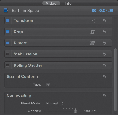
There are eight categories of built-in effects (Figure 12.2):
• Color correction (covered in Chapter 16)
• Transform
• Crop
• Distort
• Stabilization
• Rolling Shutter
• Spatial Conform
• Compositing
Figure 12.2 The built-in effects in FCP X are located in the Video tab of the Inspector.
Note: What Happened to Drop Shadow?
I don’t know. At this point, the only elements that have a built-in drop shadow effect are Titles and the shape generator. And there isn’t a filter effect that creates a drop shadow. However, you can use Motion 5 to design a drop shadow effect, plus there are some third-party shadow effects available as well.
You gain access to all built-in effects in the Inspector; however, some of these effects also have on-screen controls that you can change using the Viewer. I’ll show you how these work as you go through this chapter.
With the Inspector open, click the Video tab to reveal the built-in effects. Each effect has several standard interface elements (Figure 12.3).
• The checkbox, on the left, turns an effect on (blue) or off (black). You can temporarily disable a setting without changing any of the values in it, by unchecking the checkbox. In this example, two effects are turned on (Transform and Crop) and two are turned off (Distort and Stabilization). This checkbox makes it easy to compare how a clip looks with, or without, an effect simply by clicking this on or off. Each of these is off by default.
• The blue words Show and Hide toggle the display of individual settings for this effect. The words appear only when the mouse rolls close to them. Click the word Show to reveal the specific settings available for each effect. Click the word Hide to hide them again.
• The icon next to the word Show is a toggle to display the on-screen controls in the Viewer. As these icons vary by effect, they will be discussed individually below.
• The curved arrow on the right is the reset button for the entire effect. This resets all the settings for a specific effect back to its default state. There is no master reset for all built-in effects, just a reset for each effect.
• Just to the right of the reset button is a small, downward-pointing arrow. This reveals the parameter pop-up menu (Figure 12.4). This allows you to reset that specific setting, or work with keyframes. This arrow appears only when your mouse rolls close to it. I’ll discuss keyframes in more detail after the Transform section in this chapter.
Figure 12.3 The five standard interface elements: enable/disable an effect, show effect parameters, display on-screen controls, reset an effect, and the triangle on the far right displays a pop-up menu of additional options.
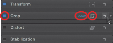
Figure 12.4 The built-in effects parameter pop-up menu lets you reset specific settings.

You can copy effects from one clip to another by first copying the clip that contains the effects you want to copy and pressing Command+C (or choose Edit > Copy). Then select one or more clips that you want to copy the effects to, and choose Edit > Paste Effects. If you have any filters or built-in effects settings applied to the selected clips, the pasted settings will override them.
Note: Can I Paste Just Some Effects from One Clip to Another?
No. Unlike in FCP 7, you can’t specify which effects get pasted. All filters and effects settings associated with the first clip get pasted into the second clip.
As you add transitions or effects to clips, an orange bar appears at the top of the Timeline. This indicates that rendering is needed. Fortunately, rendering occurs in the background, so you don’t need to wait for it to finish to keep working. For more on rendering, see Chapter 10.
Transform Effects
Transform effects control basic image sizing and positioning (Figure 12.5). Here’s what these settings do specifically:
Figure 12.5 The Transform effects control size, position, rotation, and anchor point.
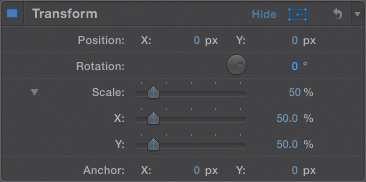
• Position. This determines the horizontal and vertical position of an element. Position moves the center of the image relative to the center of the frame. In the X box negative numbers move left, and positive numbers move right. In the Y box, negative numbers move down, and positive numbers move up. Negative numbers move left and down. Positive numbers move right and up.
Note: Positioning Changed in FCP X
Apple changed how the vertical position gets calculated from Final Cut Pro 7. In FCP 7, negative numbers moved up. In FCP X, negative numbers move down. Now, FCP X matches the same coordinate geometry system you learned in high school.
• Rotation. This controls the rotation of the selected element.
• Scale. This controls the size of the selected element. Keep in mind that all video elements are bitmapped. This means quality starts to be lost as you scale elements larger than 100 percent. Twirl down the small arrow next to the word Scale to adjust horizontal and vertical scaling separately.
• Anchor Point. This controls the point around which the selected element scales or rotates. By default, the anchor point is in the middle of the frame. The only place you can change the anchor point is in the Inspector; there are no on-screen controls for this. And you can’t use the Distort tool to move it, as you could in FCP 7, because there is no specific Distort tool in FCP X.
Change Settings
To change a setting, either click the numeric value, so it turns blue, and enter a number; or, where available, slide a slider. Even cooler, click any number and drag up or down. This is the fastest way to change a setting.
While the Inspector is a perfectly fine place to change all these settings, it is not the most convenient. The Transform settings are much easier to see and control using the on-screen controls in the Viewer.
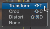
There are three ways to display the on-screen controls:
• Click the icon (blue in this screen shot) in the lower-left corner of the Viewer (Figure 12.6). Blue means the icon is active, gray means it is not.
Figure 12.6 The easiest way to display the on-screen controls is using these three icons in the lower-left corner of the Viewer. This blue icon toggles Transform settings on and off.
• Click the icon in the Inspector just to the left of the reset button for the Transform effect (see Figure 12.3).
• Press Shift+T.
To change the scale of the image display, but not the image itself, click the percentage number in the top-right corner of the Viewer and select the zoom ratio you want. You can also press Command+[plus] and Command+[minus], or Shift+Z, to rescale the image display to fit the entire image into the Viewer (Figure 12.8).
Figure 12.8 The Viewer contains three interface elements: A percentage number shows the scale of the image display, Done closes the on-screen effects, and the small box lets you move around an oversized image.

To accept your changes, do one of the following:
• Click the blue icon in the lower-left corner of the Viewer.
• Click the blue icon at the right of the Transform section of the Inspector.
• Press A to return to the Select tool.
• Click the Done button at the top-right corner of the Viewer. (I generally use this option.)
If you magnify the image display larger than will fit in the Viewer, a small white box with a red rectangle in it appears. Drag the mouse inside the white square to move around the image. This box disappears when the entire image is displayed in the Viewer. (You can also move around using the Hand tool from the Tool menu.)
Controls Specific to Tranform Effects
These on-screen controls appear for almost all the built-in effects, so now that I’ve mentioned them, I won’t need to cover them again. However, there are also several controls specific to Transform effects that I want to show you next.
Note: On-screen Controls
On-screen controls for built-in effects work only for clips in the Timeline, not for clips in the Event Browser.
Click the blue rectangular icon in the lower-left corner of the Viewer to turn on the on-screen controls for Transform, or press Shift+T (Figure 12.9).
Figure 12.9 The blue dots and center dots are the on-screen Transform controls.

Scaling the Image
Around the edges of the image, eight blue dots appear. These allow you to scale the image. Drag a corner dot to scale while maintaining the aspect ratio of the image. Drag an edge dot to scale without maintaining the aspect ratio. If you press the Shift key while dragging a control point, you override the aspect ratio.
Tip: A New Way to Constrain Image Movement
If you drag inside the image, you can move it anywhere. However, if you drag the circle in the center and press the Shift key at the same time, you constrain movement to either horizontal or vertical movement. Just discovered this. Very cool.
Press the Option key while dragging a control point to anchor the side, or corner, opposite where you are dragging. (Try it. This is easier to see than to explain.) Press both Shift and Option while dragging, and watch what happens.
The circle in the center allows you to position the image, but frankly, dragging anywhere inside the image will work. (Holding the Shift key while dragging this center circle constrains movement to 45-degree increments.)
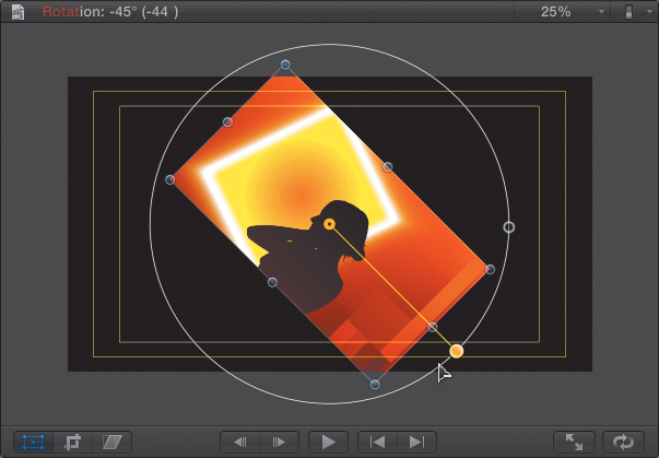
Rotating the Image
The dot to the right of the center circle controls rotation (Figure 12.10). If you drag it to the right, the pivot bar expands, allowing you to be much more precise in rotating an image. The rotation dot glows gold when the Shift key is pressed, indicating rotation is constrained to 45-degree increments.
Figure 12.10 Drag the dot to the right of the center for rotation. Press the Shift key while dragging to constrain movement to 45-degree increments.
When you are done making changes, click the Done button.
Putting It All Together
Here’s an example of a Transform effect, along with the settings that achieved it (Figure 12.11). The image is scaled to 50 percent and positioned to the top-right corner of Action Safe by adjusting the position X and Y coordinates. (X controls horizontal position, and Y controls vertical position.)
Figure 12.11 This is an example of the settings for a 50 percent scaled and repositioned image.
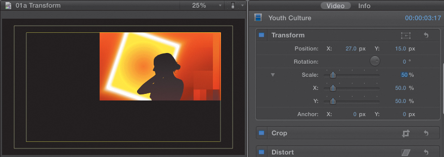
Just as a reminder, you turn the Action Safe rectangles on and off by using the Switch at the top-right corner of the Viewer.
Animate Using Keyframes
Another feature that runs through all effects (not just the built-in effects) in Final Cut Pro is that you can use keyframes for almost every parameter.
Note: Definition of Keyframe
A keyframe is a point of change during playback. Keyframes are used to provide animation with flexibility and precision. Corollary: You always apply keyframes in pairs—a starting position and an ending position. If you’re using more than two keyframes, it is often easiest to think about them in pairs.
For example, let’s say you want that last image, where it is scaled at 50 percent and positioned at the top and right corner of Action Safe, to fly into that position from full-screen. You do that using keyframes.
There are three ways to set keyframes: by way of the Viewer, the Inspector, and the Timeline. Let’s take a look at each method.
Set Keyframes in the Viewer
To set keyframes in the Viewer, follow these steps:
1. Select the clip you want to animate and position the playhead where you want the animation to start; this is not always at the beginning of a clip. (I often add markers to remind me where I want the animation to change; however, markers are not necessary to set keyframes.)
2. Turn on the Transform controls by clicking the Transform icon in the lower-left corner of the Viewer, or press Shift+T. Position the playhead on the frame in the Timeline where you want to create a keyframe.
3. Click the gray diamond in the cluster of three icons in the top-left corner; the diamond immediately turns gold (Figure 12.12). Gray indicates no keyframe at the position of the playhead; gold indicates the playhead is parked on a keyframe.
Figure 12.12 To add a keyframe in the Viewer, click the gray diamond. It turns gold when the playhead is parked on a keyframe.

When you create keyframes in the Viewer, you are setting keyframes for every parameter in Transform. (See all the gold diamonds in Figure 12.13? Each of those is a separate keyframe.) Setting keyframes in the Viewer is easy, but it often sets way more keyframes than you need. Read on for what I think is a better option.
Figure 12.13 Setting keyframes in the Viewer is easy, but it creates keyframes for every Transform parameter.

4. Because you need to set keyframes in pairs—a starting value and an ending value—move the playhead where you want the animation to end. Then, adjust the image to its ending position and set another keyframe. Unlike FCP 7, FCP X does not set keyframes automatically.
Tip: Setting Keyframes
I often find it easier to create the ending position of an effect and set a keyframe. Then, move to the opening position and set a keyframe. Working from the finished effect backwards is often easier and faster.
For effects that change position, the Viewer displays a red line trailing after the image. That’s called a motion path; it shows how the center of the image moves from the first to the last keyframe.
5. When you have the final position set to your satisfaction, either click the Done button, press A to select the Arrow tool, or click the Transform icon at the bottom left of the Viewer. This locks all the settings so they don’t change during playback.
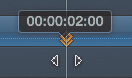
6. To navigate to the previous keyframe, click the left arrow at the top left of the Viewer (Figure 12.14). To go to the next keyframe, click the right arrow. While I am not a fan of setting keyframes in the Viewer, I am a fan of using these arrows for navigation.
Figure 12.14 It is important to use these keyframe navigation controls in the Viewer to move between keyframes to avoid moving the playhead to the wrong position.
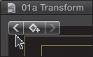
These navigation buttons are big, easy to see, easy to click, and guarantee that you are jumping exactly from one keyframe to the next. Never jump between keyframes by dragging the mouse—it is not only slow, but also highly inaccurate. All too often, you end up just missing the keyframe you want and creating a new keyframe where you don’t want it, thereby totally messing up your animation. Always jump between keyframes using these arrows, or similar arrows in the Inspector.
The good news about setting keyframes in the Viewer is that it’s easy. The bad news is that you often create more keyframes than you need, and this can cause confusion later as you try to figure out why your effect isn’t working the way you expect.
To delete a keyframe, position the playhead on the frame containing the keyframe you want to delete (the diamond glows gold), and click the diamond. If the diamond icon is gray, clicking it sets a keyframe. If the diamond icon is gold, clicking it deletes a keyframe. It’s a toggle.
Tip: Changing Parameter Settings
When you are in the Inspector, a quick way to change a parameter value, like Scale or Position, is to click the value itself and drag up/down or left/right. Watch what happens! Very cool. You could also just type in the value, but that’s pretty boring.
Set Keyframes in the Inspector
Let’s try this same effect another way in the Inspector.
In all cases when you want to add a keyframe, position the playhead on the frame where you want to add the keyframe and select the clip. (Press the Option key when clicking with the skimmer, to avoid changing the location of the playhead.)
In this case, I opened the Transform settings in the Inspector (by clicking the word Show, remember?) and added a keyframe for Position by clicking the gray diamond. Notice that the diamond turns gold; this means that a keyframe was added at the current position of the playhead (Figure 12.15).
Figure 12.15 To add a keyframe in the Inspector, click the gray plus button next to the parameter you want to set. In this screen shot, I’m about to add a keyframe for Scale because the icon hasn’t turned gold yet.

Tip: A Warning First
If you create keyframes in the Inspector, you should make sure you haven’t made any changes in the Viewer and the on-screen controls are turned off, or you will get strange and unexpected results.
The benefit of adding keyframes in the Inspector is that you are only adding keyframes for the parameters you need, which makes figuring out problems a lot easier. However, it takes practice to figure out which keyframes you need to set.
Again—and this is important—move the playhead where you want the animation to stop, then add a new keyframe before adjusting the image. If you don’t add a new keyframe where you want the animation to end, you’ll unintentionally alter the previous keyframe. Notice that since you are setting keyframes in the Inspector, only the parameters that changed need keyframes; Rotation and Anchor have none.
Setting Keyframes in the Timeline
There’s a third option for setting and adjusting keyframes: the Timeline. Simply follow these steps:
1. Select the clip you want to apply keyframes to and choose Clip > Show Video Animation, or press Control+V.
Above the selected clip are options to add keyframes for most of the built-in effects. In this case, you want to add keyframes for Transform (Figure 12.16).
Figure 12.16 Pressing Control-V allows you to set, modify, or delete keyframes in the Timeline.
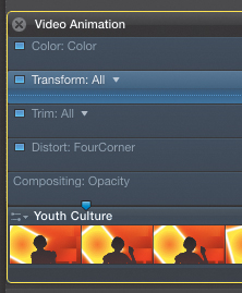
2. Click the small downward-pointing arrow next to the word Transform to reveal a pop-up menu (Figure 12.17).
Figure 12.17 Click the small downward-pointing arrow next to Transform to display a pop-up menu.

3. Choose All if you want to apply keyframes to every Transform parameter. Or choose just the parameter you want to apply a keyframe to. In this case, choose Position.
4. To add a keyframe, choose Modify > Add Keyframe to Selected Effect in Animation Editor, or press Option+K.
A keyframe now appears in the Timeline at the position of the playhead or skimmer. (You can also Option-click the horizontal line to set or remove a keyframe.)
5. Switch between parameters using the pop-up menu to select the next parameter you want to add keyframes for, and press Option+K, which sets a keyframe at the position of the skimmer or playhead.
6. Move the playhead to where you want the animation to end, and add new keyframes for each parameter. Remember, keyframes are always added at the position of the skimmer, or playhead, if the skimmer is not active.
7. To delete a keyframe in the Timeline, click it to select it (turn it gold) and press the Delete key. Make sure the keyframe is gold; otherwise, you’ll delete the clip.
One of the advantages of creating keyframes in the Timeline is that if, by mistake, you set the keyframe in the wrong place, it is easy to drag it where you want it to go. Drag horizontally to change the timing. Drag vertically to change the value (Figure 12.18). (Not all keyframes can be dragged vertically.)
Figure 12.18 To change the position of a keyframe, drag it sideways. To change its value, drag it up or down.
Summary of the Process for Setting Keyframes
Whether you add keyframes in the Viewer, the Inspector, or the Timeline, the process is always the same:
1. Set the playhead on the frame you want the animation to start.
2. Add keyframes to the settings you want to change.
3. Change the settings.
Tip: Keyboard Shortcut
You can jump between keyframes using two keyboard shortcuts:
• Press Option+; [semicolon] to jump to the previous keyframe.
• Press Option+’ [single quote] to jump to the next keyframe.
4. Move the playhead to the frame where you want the animation to stop changing.
5. Add new keyframes.
6. Adjust the image, which modifies the keyframe settings.
7. Repeat the steps until the entire animation is complete.
The animation I was creating here was a simple move between two positions. Many animations are just this simple, though they will often involve other parameters. Other animations can be much more complex, involving a number of intermediate steps.
As long as you keep in mind that you are always working one parameter at a time, setting keyframes in pairs, you won’t get lost, even in the most complex piece of animation.
Trim, Crop, and Ken Burns
A lot of what I covered in the Transform section is exactly the same for the rest of the built-in effects. So let me simply point out the differences as you move through the rest of this chapter.
The Crop parameter has three sections: Trim, Crop, and the Ken Burns effect.
• Trim. This acts like Crop in Final Cut Pro 7. It makes the edges of a clip transparent, without changing the size of the clip.
• Crop. This makes the edges of a clip transparent, then expands the remaining image to fill the frame. Keep in mind that image quality will degrade the more you expand an image.
• Ken Burns. This effect provides an elegant way to do moves (pans, tilts, and zooms) on an image. While this effect is generally used on still images, it works equally well on video, though with some degradation in image quality caused by zooming in on the image.
You have three ways to access these effects:
• On-screen controls in the Viewer
• The Inspector
• Video animation in the Timeline
Note: What Are Pan, Tilt, and Zoom?
To pan is to move an image side to side, horizontally—for example, “Pan the camera right.” To tilt. is to move an image up and down, vertically—for example, “Tilt up to show the sky.” To zoom is to enlarge an image by adjusting the lens—for example, “Zoom in so I can see the detail.”
Since the video animation controls work the same as for Transform, I’ll illustrate the first two options for each of these three settings.
As always, first select the clip you want to modify in the Timeline.
Whether you want to trim, crop, or create a move on an image, either click the Crop icon in the lower left of the Viewer, or click the same icon to the right of the word Crop in the Inspector, or press Shift+C. This displays the on-screen controls in the Viewer (Figure 12.19).
Figure 12.19 Click the crop icon in the lower-left corner of the Viewer to display the on-screen controls for Crop, Trim, and Ken Burns.

In the top-left corner of the Viewer are six buttons, from left to right (Figure 12.20): Trim, Crop, Ken Burns, and the three keyframe buttons you learned about in the Transform section.
Figure 12.20 The three buttons on the left control effects. The three on the right set and navigate between keyframes.

Trim
Click the Trim button to display the Trim controls. Trim removes the edges from a clip without changing the size or position of the clip. In Trim mode, the control points are blue rectangles and triangles (Figure 12.21). These blue controls are shaped differently from those you saw earlier for Transforms, or in the next section for Crops.
Figure 12.21 This is a full-screen image with the blue Trim controls enabled and displayed. Note the blue crop icon in the lower-left corner.

Tip: Get Out of the Way!
If the Trim/Crop/Ken Burns buttons at the top of the Viewer get in your way, change the size of the Viewer by dragging the edge of the window. This should also change the aspect ratio enough so that the buttons are no longer in the way. This is what I did in Figure 12.21.
Drag one of the blue controls. Dragging an edge only affects that edge. Dragging a corner affects two edges. Watch what happens when you drag while pressing the following keys:
• Shift. This trims while constraining to aspect ratio.
• Option. This trims opposite edges.
• Both. This trims the opposite edges while constraining the aspect ratio.
The yellow guides show you where the center of the image is, vertically and horizontally. They appear as you start dragging stuff around.
When you are done dragging, everything outside the trimmed area is transparent (Figure 12.22). If there is a clip below this on the Timeline, you’ll see it. If not, you’ll see black. And this is really black; unless you export using Apple ProRes 4444, in which case the black area will be transparent.
Figure 12.22 Here is the same image with a trim applied. Note that parts of the image are now missing. Trimming doesn’t scale an image; it removes portions of it.
You could get the same result by dragging sliders in the Inspector. Set the Type pop-up menu to Trim, then click Show to display the individual settings. But using the on-screen controls makes this both faster and easier.
When you are happy with how the effect looks, click one of the following:
• Done in the top-right corner of the Viewer
• The blue crop icon in the top-right corner of the Inspector
• The blue crop icon in the lower-left corner of the Viewer
• Press A to return to the Arrow tool
Tip: What If I Change My Mind?
You already know the answer: Click the Reset button (the arrow) in the Crop section of the Inspector. All the Crop settings reset to normal.
The key benefit to using Trim is that you are not changing the size or position of the clip, just hiding parts of it. (No, this is not permanent. If you display the on-screen settings again, you can re-adjust the trim—as many times as you want.)
Crop
Cropping does the same thing trimming does, except it then takes the result and enlarges it so it fills the frame. Here, you need to be careful because if you scale an image larger than 100 percent, it will degrade quality. While this will rarely happen with high-resolution stills, it is very common when scaling video. Because Crop is designed to fill the frame, you can only trim the image in the same aspect ratio as your Project.
Here’s how this works.
1. Click the same Crop icon in the Viewer or the Inspector, or press Shift+C (as you did in Trim) to display the on-screen controls.
2. Click the Crop button at the top left of the Viewer. Notice that the controls have changed: The blue rectangles in the middle of an edge are gone, and the shape of the four corner controls has changed.
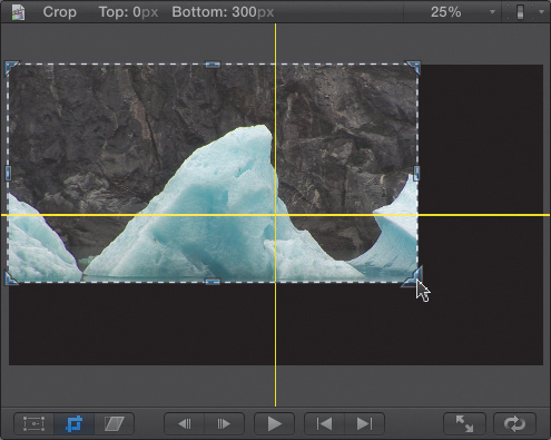
3. Drag a corner and watch how the crop rectangle maintains the shape of your Project and highlights a portion of the image (Figure 12.23).
Figure 12.23 This is the same iceberg image that you trimmed earlier. The crop rectangle is over a portion of the image, in the same aspect ratio as that of the Project.

4. Drag the middle of the image to reposition the selected area. Areas of the image outside the crop are dimmed. When you are done, only the area inside the crop will be displayed in your Project.
5. To accept the Crop, click Done (or one of the crop icons). The cropped image is immediately enlarged to fill the entire frame (Figure 12.24).
Figure 12.24 The finished crop enlarges the selected area to fill the frame.

You could get the same result in the Inspector, by setting the Type pop-up menu to Crop and adjusting the sliders. But for me, the on-screen controls are far faster and more intuitive.
Figure 12.25 This is an image enlarged about 1000 percent to display the individual pixels in an image. Overenlarging a clip reduces image quality.

Ken Burns Effect
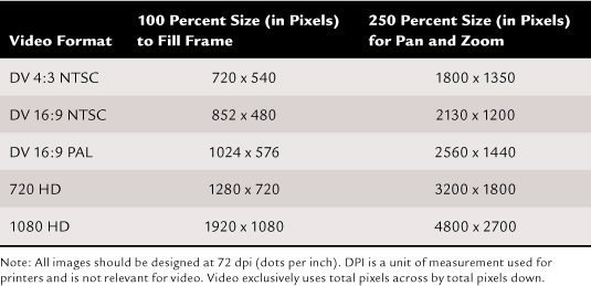
The Ken Burns Effect is named after legendary documentary filmmaker Ken Burns, who revolutionized documentaries with his innovative use of movement on stills. He has now been immortalized in software. This effect works best with still images. More important, it works best with still images that are larger than the frame size of your Project. Table 12.1 suggests some image sizes.
Table 12.1 Sizing Still Images for Moves
The whole reason to use this effect is to create the illusion of movement in a still image, or in a video clip that wasn’t shot with movement.
Here’s how this works:
1. Select the clip you want to apply the effect to, and display the on-screen controls (yup, click the crop icon or press Shift+C). (By the way, this effect can only be done on-screen; there are no Inspector controls for this.)
2. Click the Ken Burns button at the top left of the Viewer.
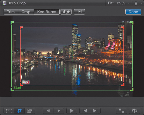
Two frames are displayed: green and red (Figure 12.26). Both rectangles match the aspect ratio of your Project. (This is a still of the Yarra River in Melbourne, Australia.) The green rectangle indicates where the clip starts, and the red rectangle indicates where the move ends. The default move is a slight zoom into the center of the frame.
Figure 12.26 This is the default setting of the Ken Burns effect. The green rectangle signifies the starting position, while the red rectangle indicates the ending.
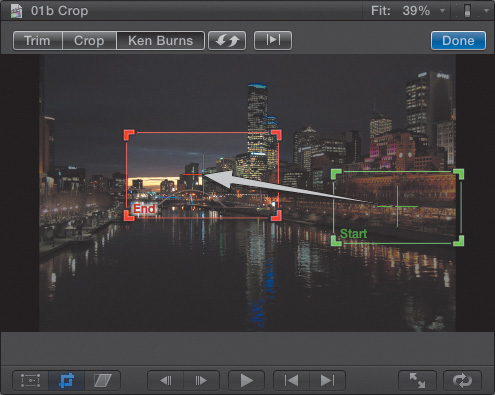
3. For instance, here I resized and positioned the green rectangle to start with a close-up of the right-side waterfront, then sized and positioned the red rectangle to do a move back to the bridge and skyline. The white arrow indicates the direction of the move (Figure 12.27).
Figure 12.27 The images are resized and repositioned to pan slowly along the waterfront from the green to red rectangle.
4. Click the dual lightning symbol at the top to switch the position of the red and green rectangles.
5. Click the right-pointing triangle at the top to preview the effect.
6. When you are happy with the results, click Done.
Tip: Render the Ken Burns Effect
As with all effects in Final Cut Pro, you can preview the effect before rendering is complete. However, in the case of the Ken Burns effect, the playback will be jerky and the image quality severely reduced. Complete the rendering before making any final judgments on the effect.
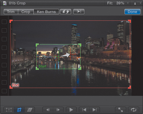
Here’s another example. This starts with a close-up of the bridge and zooms back to show a wide shot of the city (Figure 12.28). When you are happy with the effect, click Done.
Figure 12.28 This is another example of starting close and zooming out to the entire scene.
Sizing still images for moves gets really confusing. The basic idea is that if you are doing moves on a still image, that image needs to be bigger than the frame size of your Project.
Since all video is measured in pixels, Table 12.1 will help you size images. The left column presents some popular video formats. The middle column shows size dimensions that let you create an image that perfectly fills the frame but doesn’t allow moves. The right column contains dimensions that both fill the frame and allow moves, including zooms up to 250 percent.
Distort, or Corner Pinning
Distort, also called “corner pinning,” lets you take an image and manipulate it to give it a sense of perspective, or location in space. FCP X doesn’t work in 3D space (though it can in combination with Motion 5). All you are doing here is providing the illusion of 3-D.
In Final Cut Pro 7 you used the Distort tool. In FCP X you can use either the on-screen controls in the Viewer or in the Inspector. In this case, the on-screen controls are far easier to use.
1. To distort a clip, select the clip, then do one of the following:
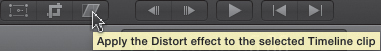
• Click the Distort button in the lower-left corner of the Viewer (Figure 12.29).
• Right-click in the Viewer and choose Distort.
• Press Shift+Command+D.
• Go to the Distort section in the Inspector.
Figure 12.29 Click the Distort button to display the on-screen controls.
2. When the on-screen Distort controls are turned on, a series of blue control dots appears around the edges of an image (Figure 12.30). Drag a corner to reposition it; drag an edge to reposition both corners at the same time. You can even drag corners outside the frame—although once they go out of the frame, that portion of the image disappears.
Figure 12.30 Using Distort, you can reposition each corner—even move it outside the frame!
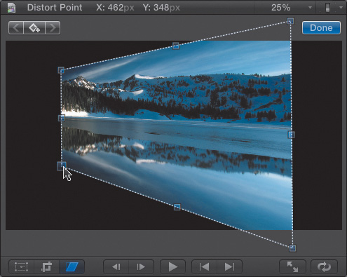
3. Drag the middle of the image to reposition the entire image. (When you reposition the entire image, you are actually adjusting the Transform settings.)
In this example, the image has a sense of flying back in space, with the right side exploding out the front of the frame. This is a very popular technique to create the illusion of an image playing on a screen, or of the side of a building.
4. When you are happy with the Distort settings, either click the Done button, press A to select the Arrow tool, or click the blue Distort button in the lower-left corner of the Viewer.
5. To reset the settings back to their default, go to the Inspector and click the curved arrow to the right of the Distort settings. And, as with the Transform settings, you can use the Inspector to keyframe each of the four Distort corners to animate the distortion of the clip during playback.
Image Stabilization
High-definition images accentuate camera shake. This means the bigger your image will be viewed, the more stable your image needs to be. However, sometimes during production there just isn’t time—or, more accurately, there doesn’t appear to be the time—to put the camera on a tripod or dolly to stabilize the shot.
FCP provides an option to solve this problem by analyzing your image to reduce the apparent movement. FCP looks at how the image moves in the frame, then moves the image in the opposite direction. For example, if the image moved down during filming, FCP moves the image up by the same amount, giving the illusion of a stable image.
Image stabilization requires analysis, and FCP allows you to analyze your clips during import, after import in the Event Browser, or once they are edited into the Timeline. However, analyzing during import takes a long time because FCP always analyzes entire clips. This means if you are bringing in lots of long clips, it can seem as if your clips are in background processing forever.
Tip: Can I Analyze a Range Within a Clip?
No. If you need to analyze a range, edit it into a compound clip, then analyze the compound clip.
A better way to deal with this is to analyze your clips for image stabilization only when you know you are going to use them in your Project.
While you can analyze a clip in the Event Browser using Modify > Analyze and Fix, the most efficient way to analyze a clip is to do the following:
1. Edit the clip to the Timeline; analysis does not need to be complete before you can stabilize the clip.
2. Go to the Inspector (there are no on-screen controls for this), and turn on Stabilization by clicking the blue checkbox (Figure 12.31). This forces the clip to be analyzed.
Figure 12.31 Turn on the blue checkbox to enable the Stabilization controls in the Inspector.

3. FCP gets to work analyzing your clips in the background. As always, you can monitor the status of analysis using the Background Tasks window (press Command+9.)
The image instantly zooms in slightly. As you play the clip, you’ll notice it moves far less than before. Due to differences in clips and how they are shot, sometimes this stabilization is just magical. Other times, it needs adjustment. And in a few instances, it doesn’t work at all.
There are three controls you can adjust to smooth out the stabilization:
• Translation Smooth. This adjusts compensation for horizontal and vertical movement. In almost all cases this should be used. Slide this to 0 to remove the compensation. Slide it to 5.0 for maximum compensation. The default setting of 2.5 is generally a good place to start.
• Rotation Smooth. This adjusts compensation for rotational movement. Slide this to 0 to remove the compensation. Slide it to 5.0 for maximum compensation. I generally set this closer to 1.0.
• Scale Smooth. This adjusts compensation for shaky zooms. Slide this to 0 to remove the compensation. Slide it to 5.0 for maximum compensation. I generally turn this off by setting it to 0.
This is an effect that is just not possible to demonstrate in a book. However, once you try it, you’ll see how it works.
Rolling Shutter
Rolling Shutter is an artifact of rapid panning while shooting using the large, and somewhat slow, sensor in an (H)DSLR camera.
Note: What’s This Term, (H)DSLR?
To try to avoid confusion, the industry is trying to differentiate between digital cameras that just shoot stills (DSLR, or digital single-lens reflex) and those that shoot stills and high-definition video: (H)DSLR (high-definition single-lens reflex).
Here’s what the problem looks like: See how all the vertical edges of the garbage cans and the light pole are leaning to the right (Figure 12.32)?
Figure 12.32 During this pan, both the garbage cans and the gray light pole are leaning heavily to the right.

This is caused by the pan moving the image so quickly over the image sensor that the camera can’t capture the image all at one time. Instead, it captures the image moving from the top of the sensor to the bottom. (Lenses, as you know, invert the image on the sensor so the bottom is on the top.) This means that the bottom of the image is recorded slightly before the middle and top of the image are recorded. If the camera is holding still, this is not a problem, but if the camera is panning too quickly, you can get undesirable results.
To fix this, you analyze the clips using the same process used in image stabilization:
1. Edit the clip to the Timeline.
2. In the Inspector, turn on Rolling Shutter.
3. After analysis is complete, go to the Inspector and, if necessary, adjust the Rolling Shutter settings.
What FCP does is slightly zoom into the picture and shift the pixels proportionately to remove the lean (Figure 12.33). The image illustrates a medium setting, which is the default. You can minimize or exaggerate the correction by changing the settings from Low to Extra High. None turns off all image compensation. (More often than not, the default setting of Medium will be the best choice.) If you need to apply this correction to only a portion of a clip, cut the clip into sections using the razor blade (or press B).
Figure 12.33 All the edges appear properly vertical after applying a medium setting of the Rolling Shutter effect.

Keep in mind that this artifact only shows up when rapidly panning using (H)DSLR cameras. For other cameras, you can ignore it.
Spatial Conform
Spatial conform is a scary term. But it is a very useful tool because it solves a common problem: images that don’t fit the frame. While spatial conform is most often used for still images that are not in the right aspect ratio, you can just as easily use this tool for video. I find myself using it in almost every Project.
Unlike other built-in effects, Spatial Conform is always on, with three settings to select from (Figure 12.34).
Figure 12.34 There are three spatial conform settings: Fit, Fill, and None. Fit is the default.

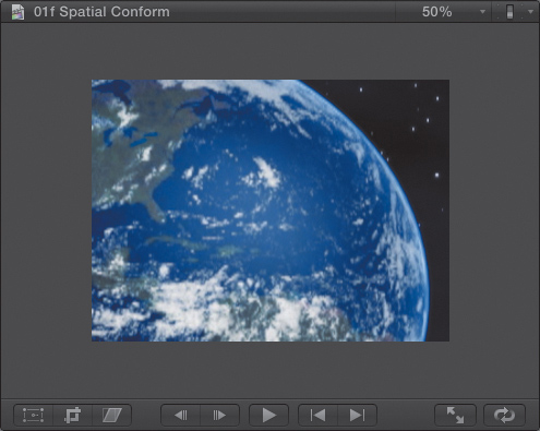
Fit. This is the default setting. It fits (by scaling) the entire image into the frame so that you see all of it (Figure 12.35). Unless the image is specifically designed to match the aspect ratio of your video, you will see around the edges—either black or, if one exists, the image below it.
Figure 12.35 This image of Earth is using the default setting: Fit. This fits the entire image into the frame, even if that means seeing around the edges.

Here’s the problem. This is a 16:9 image that is superimposed in a 4:3 Project. The underlying image, which is on the primary storyline, is showing around the edges of the planet Earth image.
Fill. This scales the image so that the entire frame is filled. Notice in this example there is no black at the top and bottom, but you’ve lost some of the image on the left and right edges. This option is the best choice when you want a still image to fill the frame when it doesn’t match the aspect ratio of the video (Figure 12.36).
Figure 12.36 This is the same image using Fill. This zooms into the image until it entirely fills the frame. Some pixels around the sides are lost.

None. This displays the image at 100 percent size, whether it fits in the frame or not. This option is the best when you want to use an image for a Ken Burns effect (Figure 12.37), or import a very small image to use within the frame.
Figure 12.37 This is the same image set to None; it displays the image at a size of 100 percent.
For anamorphic clips captured by older software, FCP will display this 16:9 clip as 4:3. Spatial Conform won’t stretch it to fit the frame. Instead, it will zoom into the clip until the image fits the frame; this results in lost pixels along the left and right edge.
FCP X does not have the ability to change the aspect ratio of a clip from 4:3 to 16:9, or vice versa. That will need to be done outside of Final Cut Pro X prior to importing the clip. At the time of writing this book, QuickTime 7 Pro was the software of choice for this; Compressor 3 or 4 will also work.
Compositing
Compositing can be defined simply as combining two or more images to form a new image. Thus almost all of the built-in effects in FCP are doing compositing in some way or another. Since a composite combines two or more images at the same time, the only way you can composite is to stack images vertically. Since FCP X allows for an unlimited number of layers in a stack, theoretically you can create some pretty dazzling effects.
Note: Alpha? Luma? What?
The alpha channel determines how transparent a pixel is. Each pixel in a clip has four values associated with it: how red it is, how green it is, how blue it is, and how transparent it is—RGB plus alpha. Luma refers to the “shade of gray” values in the image. If you were to convert the color picture into a black-and-white version, what you would be looking at is the luma—short for luminance—values of the image.
However, stacking clips creates a problem. By default, every image is 100 percent full screen and 100 percent opaque. This means that the top image always blocks any images below it. Over the course of this book, you’ll discover a range of ways to solve that problem. For now, though, you want to look at two specific built-in effects for compositing: Blend Mode and Opacity.
Both are amazingly flexible. Blend modes alone deserve an entire chapter. In fact, the best way to learn how to use blend modes is to read a Photoshop book. While blend modes are little understood in video, they are a staple of Photoshop image enhancement.
Opacity determines how opaque, or transparent, a clip is. Opacity lets you change the default clip setting of 100 percent using either the Inspector or the Timeline. (By the way, a clip that is neither opaque nor transparent is called “translucent.” Gosh! The things we learn in video editing...)
Blend modes let you combine images from two or more clips based on five criteria:
• Highlights. These are the brighter portions of the image.
• Mid-grays. These are the middle gray portions of the image.
• Shadows. These are the darker portions of the image.
• Color, also called chroma. This is the color in an image.
• Transparency. This refers to either alpha channel or luma channel.
Opacity
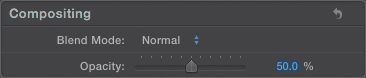
At the bottom of the Inspector are settings for Blend Mode and Opacity (Figure 12.38). This setting moves to the top of the Inspector when you are working with a Title clip.
Figure 12.38 The Opacity and Blend Mode settings are at the bottom of the Inspector.
You only need to change the opacity on the top clip. The bottom clip can be left alone. This is true for all effects—always change the top clip.
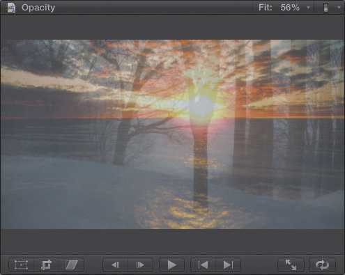
Select the clip and, in the Inspector, drag the Opacity slider left to blend the two clips; type in a value in the numeric text entry, or drag the text value up or down. In this image, Opacity was adjusted to 50 percent, thus creating a blend between a sunset and a winter scene in a forest (Figure 12.39). The top image is called “translucent.” When Opacity is set to 0 percent, the image is invisible.
Figure 12.39 Two clips were blended at 50 percent opacity for the top clip.
You can adjust Opacity in the Inspector, and you can also adjust it in the Timeline. When you adjust Opacity in the Timeline, two additional options present themselves: opacity fade handles at the beginning and end of each clip, and the ability see where you are placing keyframes (Figure 12.40).
Figure 12.40 Adjust Opacity in the Timeline by enabling video animation and dragging the Opacity keyframe line.

To reveal the Opacity controls, select the clip and either choose Clip > Show Video Animation, or press Control+V. Double-click in the Opacity box above the clip to reveal the Opacity controls. Double-click this box again to close the animation window.
Drag the horizontal black line up and down to increase or decrease opacity (the maximum value is 100 percent).
To add keyframes to the black line, which would allow you to change the opacity settings during playback, Option-click directly on the black opacity line.
To add fades to the beginning or end of the clip, which I did for this clip, drag the gray dots at either end of the clip to adjust the opacity fade handles. These work exactly the same way as the audio fade handles you discovered in Chapter 9, except these control opacity. This is a fast way to do a fade-up or fade-out on any clip without using transitions.
Blend Modes
Blend modes are used to combine textures between two images (clips or stills) that are stacked on top of each other. Blend modes combine the images based on the grayscale values of their pixels. There’s a basic rule to using these: If you like it, it’s a good effect; if you don’t like it, it’s a bad effect. There’s nothing to adjust. Take it or leave it.
Tip: Normal Is Good
“Normal” turns all blend modes off.
Blend modes are used far more than you might expect; in fact, they are central to creating believable effects. However, one place you see them a lot is in blending text with the background.
Let me just give you a few examples. Then you can experiment on your own.
The Blend menu is divided into several main categories (Figure 12.41):
• Subtract. This category combines images based on darker pixel values. My favorite here is Multiply.
• Add. This category combines images based on lighter pixel values. (Avoid using Add, by the way, which creates white levels that are too bright. Use Screen instead.)
• Overlay. This category combines images based on midtone gray values. This is my favorite blend mode, and I always try using it first.
• Difference. This category combines images based on color values.
• Stencil Alpha. This category combines images based on transparency, either alpha or luma.
Figure 12.41 There are multiple categories of blend modes, with options in each category.
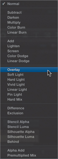
Not all of these settings work for all clips. Some will be dramatic, others much more subtle. In all cases, try it and see what you like. The three that I always try first are Overlay, Screen, and Multiply—in that order. After that, I start playing with the others.
Here are some examples.
This is a text clip that I created in Final Cut Pro (Figure 12.42). It is light gray in color and grayscale. Let’s superimpose it over a background and change the blend modes.
Figure 12.42 This is our starting clip, with light gray text.

The image in Figure 12.43 uses an Overlay blend mode. Notice how the colors from the background blend into the text, and the shadow from the background runs through the T. This creates the effect of weathered text blended into the rock’s surface.
Figure 12.43 This is the text applied to a background using the Overlay blend mode.

The image in Figure 12.44 uses the Linear Light blend mode. In this example I changed the color of the text to blue, because Linear Light works better with color text than white text. This gives more of a feeling of chalk scrawled on the rock.
Figure 12.44 This is the text applied using the Linear Light blend mode.

The image in Figure 12.45 uses the Multiply blend mode. In this example I made the text dark gray. Again, the two textures combine in ways that make the text look as if it is actually spray-painted on the rock. (By the way, this rock texture is actually a generator that ships with Final Cut Pro X. I’ll talk about generators in the next chapter.)
Figure 12.45 This is the text applied using the Multiply blend mode.

Blend modes are a great way to share textures between images and a never-ending opportunity to make your effects look more “organic” and integrated than simply adjusting opacity, or doing a key.
Special Case: Use Compound Clips for Effects
Compound clips also play a large role in creating effects. A compound clip lets you treat a group of clips as though they were a single clip. (In Final Cut Pro 7, this was called a “nest.”)
Let me illustrate with an example. I’ve stacked four clips on top of each other in the Timeline (Figure 12.46). What I want to do is rotate all of them, make them a bit darker, then add a title on top. The easiest way to do this is with a compound clip. Here are the steps:
Figure 12.46 Because I want to see four images at once, I start by stacking four clips in the Timeline. Note they all start and stop at the same time.
1. Using the Transform settings in the Inspector, scale the top clip to 50 percent size. (Use the top clip so you can see what you are doing in the Viewer.)
2. Copy this clip to the clipboard (choose Edit > Copy, or press Command+C).
3. Select the three remaining clips and choose Edit > Paste Effects. This pastes the Transform effect from the first clip to the three selected clips.
4. Using the on-screen controls for Transform, position all four clips until there is a clip in each corner of the screen (Figure 12.47).
Figure 12.47 Position your clips before you combine them into a compound clip.

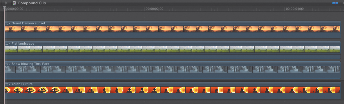
5. Select all the clips you want to combine into a compound clip, and press Option+G, or choose File > New Compound Clip. This condenses all four clips into a single compound clip stored in the Timeline (Figure 12.48). (If I had planned to use this effect with these clips more than once, I would have first created the compound clip in the Event Browser. Chapter 7 explains how.)
Figure 12.48 After combining the clips into a compound clip and adding a title, the Timeline looks like this.

6. I added the Drifting title effect from the Titles Browser on top of my clips. Then I changed the text font, changed the size of the text, and colored the bottom title. Oh, and I added a drop shadow.
7. I then selected the compound clip and, in the Transform section of the Inspector, I scaled it, rotated it, and decreased the opacity until I got to the final effect (Figure 12.49). After all these changes, when I play this effect, the video from each clip plays under the title.
Figure 12.49 This is the finished effect.

The compound clip made it easy to rotate all these separate clips and decrease their opacity. In real life, I would also blur this background and remove some of the color so the text is easier to read, but I haven’t covered those effects yet, so I’ll stop here.
Summary
The built-in effects are central to almost all the effects you create inside Final Cut Pro X. You are always looking to change the size of something, or reposition it, animate it, or blend it so that it works better for this Project.
More than any others, these are the effects you’ll use to make all that happen.
Keyboard Shortcuts
