
6
Construction of Geosynthetic Reinforced Soil (GRS) Walls
Geosynthetic reinforced soil (GRS) walls can be constructed anywhere a retaining wall is deemed warranted and practical. If the foundation soil is too weak to allow safe construction of a GRS wall, ground improvement may be needed before construction. Various ground improvement techniques have proven to be effective, and they have been presented in the literature, including recent books by Kirsch and Bell (2013) and Nicholson (2015). Typical applications of GRS walls include embankment walls, temporary or permanent widening or diversion embankment walls, earth walls on steep mountain slopes, slide stabilization walls, rock fall barrier walls, bridge abutment walls, small dams, sound barrier walls, and various urban earth wall projects where a sudden change in elevation is needed due to space constraints or aesthetics considerations.
This chapter addresses the construction of GRS walls, including construction procedures and general construction guides. Many types of GRS walls have been constructed (see Figure 3.23). This chapter, however, focuses on four common types of GRS walls: concrete block GRS walls, wrapped‐face GRS walls, full‐height precast panel facing GRS walls, and timber facing GRS walls.
6.1 Construction Procedure
This section describes typical construction procedures for four common types of GRS walls: concrete block GRS walls, wrapped‐face GRS walls, full‐height precast panel facing GRS walls, and timber facing GRS walls. These walls differ primarily in facing and connection between the facing and the reinforced soil mass.
6.1.1 Concrete Block GRS Walls
The typical construction sequence of concrete block GRS walls is illustrated in Figure 6.1 and can be described as follows:
- Step 1: Level the wall site by removing vegetation, large rocks, stumps, etc.; excavate a shallow trench (about 450 mm or 18 in. wide and 75–150 mm or 3–6 in. deeper than the embedment depth of facing, as per construction plans of the wall project) along the planned location of the concrete block facing (Note: For recommended design embedment depth, see item (a) Embedment, Step 12, Section 5.7.1); then place and level a compacted sand‐gravel pad of thickness 75–150 mm (3–6 in.) inside the trench.
- Step 2: Position the first course of concrete facing blocks over the sand‐gravel pad; check alignment and ensure that the blocks are level; (optional) place aggregates to fill the hollow cores of the blocks and the space between the blocks; and sweep away the debris on the top surface of the blocks.
- Step 3: Place free‐draining fill material behind the facing blocks all the way to the back of the wall, as per construction plans; compact the fill until it matches the top surface of the blocks.
- Step 4: Lay down a layer of geosynthetic reinforcement to cover the compacted fill and the facing blocks (the front of the reinforcement should be slightly behind the front edge of the blocks and should extend to the design length as measured from the back of the blocks); pull the reinforcement taut.
- Step 5: Position a subsequent course of concrete facing blocks over the previous course of blocks; backfill and compact the fill behind the concrete blocks until the compacted fill matches the top of the newly placed facing blocks.
- Step 6: Repeat Steps 4 and 5 for subsequent courses of concrete blocks and compact the newly placed fill until the top surface of the fill reaches the design wall height.
- Step 7: Add concrete mix in the cores of the uppermost 2–3 courses of blocks to help tie those blocks together. The geosynthetic reinforcement embedded between those blocks will need to be perforated with a knife or weed burner to allow the concrete mix to flow into the blocks underneath. For load‐carrying applications (e.g., bridge abutment walls), the concrete mix will need to be reinforced by vertical rebar. The last course of blocks is usually capped according to the block manufacturer’s recommendation. Weed burner may be used to remove visible excess reinforcement protruding from the wall face.
Figure 6.1 Typical construction sequence of concrete block GRS walls
Figure 6.2 shows photos taken during the construction of concrete block GRS walls. Below are a few notes about the construction of concrete block GRS walls:
- Before construction, measures for control of surface and subsurface water at and around the construction site (see Section 6.2.5) should be undertaken to prevent any potential drainage problems.
- Some wall builders use a concrete footer at the wall base to facilitate alignment of concrete facing blocks. A compacted sand‐gravel pad, however, has been found to help in aligning the blocks and alleviating potential cracking of facing blocks better than a concrete footer.
- When a wall involves corners, it is important to compact the fill to the same degree as the rest of the reinforced fill. This may be achieved by employing heavy hand‐operated tempers or other tools for fill compaction behind the corner. Use of a dry concrete mix in the cores of the corner blocks and reinforced with No. 4 vertical rebar has been proven effective in eliminating cracks or separation of blocks at corners.
- Although many designers routinely use a slight batter for facing blocks, vertical stacking works equally well for walls of low to medium height (i.e., heights not greater than 20 ft or 6.0 m). Facing batter can help reducing lateral movement and masking minor lateral movement; however, the reduction is generally not needed for walls of low to medium heights in non‐load‐bearing applications.
- Shorter reinforcement (1‐m or 3‐ft long), referred to as Colorado Transportation Institute tails, or simply CTI tails, may be used in every other reinforcement layer, as shown in Figure 6.3. When CTI tails are used, great caution needs to be exercised during construction to avoid confusion on sequencing of alternating reinforcement length. If there is any doubt that strict construction control may not be carried out, uniform full‐length reinforcement is recommended, especially for smaller projects.
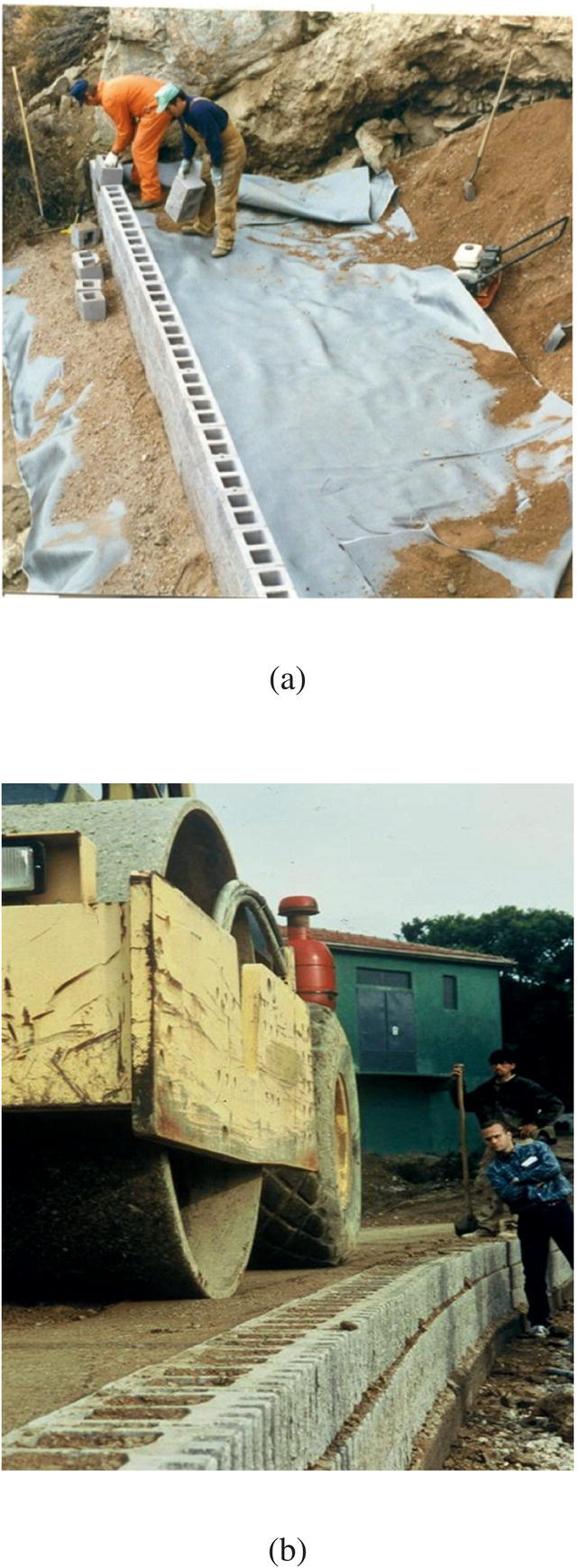

Figure 6.2 Construction of concrete block GRS walls: (a) placement of facing blocks, (b) compaction of fill behind facing, and (c) near completion of a GRS abutment wall
Figure 6.3 GRS wall with CTI tails (shorter reinforcement in place of full‐length reinforcement in alternating layers)
6.1.2 Wrapped‐Face GRS Walls
There are two types of wrapped‐face GRS walls, differing in the forming elements used during construction and their final appearance: (i) geotextile wrapped‐face GRS walls, referred to as temporary form‐work walls, and (ii) wire‐mesh wrapped‐face GRS walls, referred to as permanent form‐work walls. For the former, the construction form is temporary L‐shaped metal brackets in combination with wooden running boards (see Figure 6.4); for the latter, the construction form is continuous L‐shaped wire‐mesh (see Figure 6.5). Geotextile wrapped‐face GRS walls were developed by the U.S. Forest Service in the 1970s. They are one of the least expensive types of earth retaining wall developed to date, and have been used in many parts of the world. Wire‐mesh wrapped‐face GRS walls, on the other hand, have only gained increasing popularity since the 2000s. They have a distinct advantage over geotextile wrapped‐face GRS walls in that the form is left in place hence results in more rapid construction. The following describes the construction sequence of the two types of wrapped‐face GRS wall.
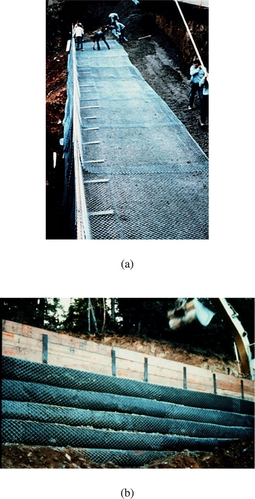
Figure 6.4 Construction of a geotextile wrapped‐face GRS wall (temporary form‐work wall) with metal L‐shaped brackets and wooden brace board: (a) top view and (b) front view (shown is a chain‐link wall with wrapped‐face geotextile)
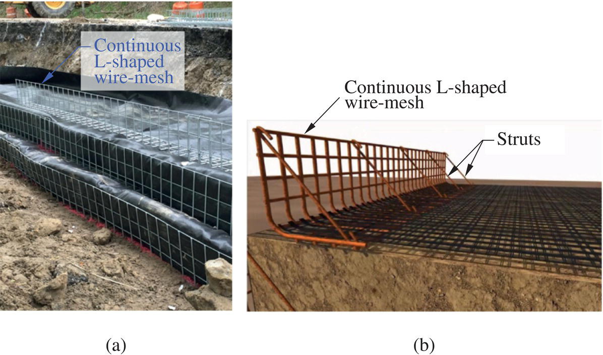
Figure 6.5 (a) Wire‐mesh wrapped‐face GRS wall (permanent form‐work wall) with continuous L‐shaped wire‐mesh brackets (courtesy of Bob Barrett) and (b) continuous L‐shaped wire‐mesh with struts (courtesy of Strata Systems, Inc.)
Geotextile Wrapped‐Face GRS Walls (Temporary Form‐Work Walls)
A schematic diagram of geotextile wrapped‐face walls (temporary form‐work walls) is seen in Figure 3.23, and a completed wall is shown in Figure 3.24(a). The typical construction sequence of geotextile wrapped‐face GRS walls (temporary form‐work walls) is illustrated in Figure 6.6, and can be described as follows:
- Step 1: Level the wall site and install a series of L‐shaped forms (of height slightly taller than design layer thickness) on the ground surface. The L‐shaped form is composed of metal L‐shaped brackets and continuous wooden brace boards along the wall face (see Figure 6.4).
- Step 2: Lay down a sheet of geotextile over the soil surface and L‐shaped forms by positioning the geotextile sheet in such a way that 1 m (3 ft) of the sheet is draped over the top of the form; backfill to about ½–¾ of the lift thickness, and compact the fill with conventional light‐weight earth‐moving equipment.
- Step 3: Make a windrow 0.3–0.6 m (12–24 in.) from the wall face using a road grader or by hand; fold the loose end of the geotextile sheet over the L‐shaped form into the windrow. When making windrows, care needs to be exercised not to damage the geotextile beneath or at the face.
- Step 4: Backfill and compact the remaining lift thickness; remove the form from the layer below and reset it over the top of the soil layer. Typical layer thickness ranges from 0.2 to 0.45 m (8 to 18 in.), with 0.3 m (12 in.) being the most common.
- Step 5: Repeat Steps 2 through 4 for subsequent layers until the design height is reached. For the final layer, the fold‐back length should be extended to at least 1.8 m (6 ft) behind the wall face (preferably extend to the full length of the reinforcement layers) and covered with about 150 mm (6 in.) of fill.
- Step 6: If needed (e.g., for a more “permanent” wall), cover the exposed face of the wall with shotcrete (wet‐mixed concrete or mortar conveyed through a hose and pneumatically projected at high velocity onto the wall surface), bituminous emulsions, or other asphalt products to prevent weakening of the geotextile due to UV exposure and vandalism (see Figure 6.7).
Figure 6.6 Typical construction sequence of geotextile wrapped‐face GRS walls (temporary form‐work walls)
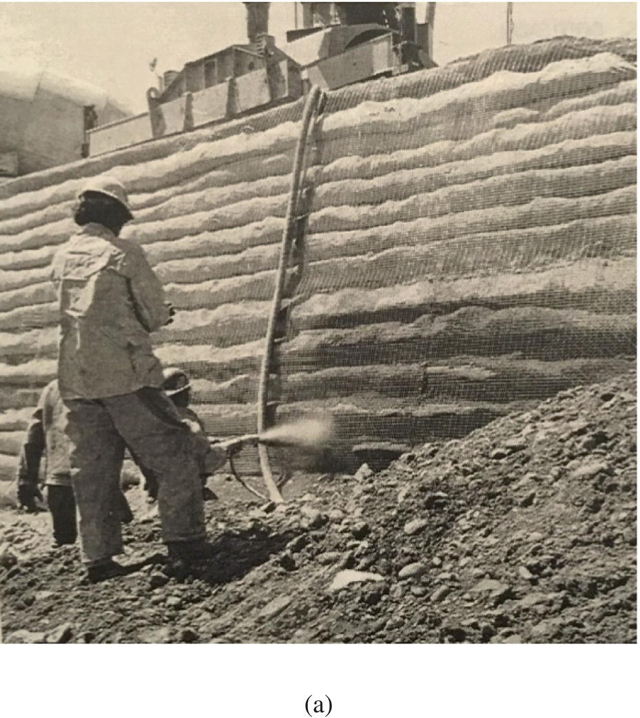
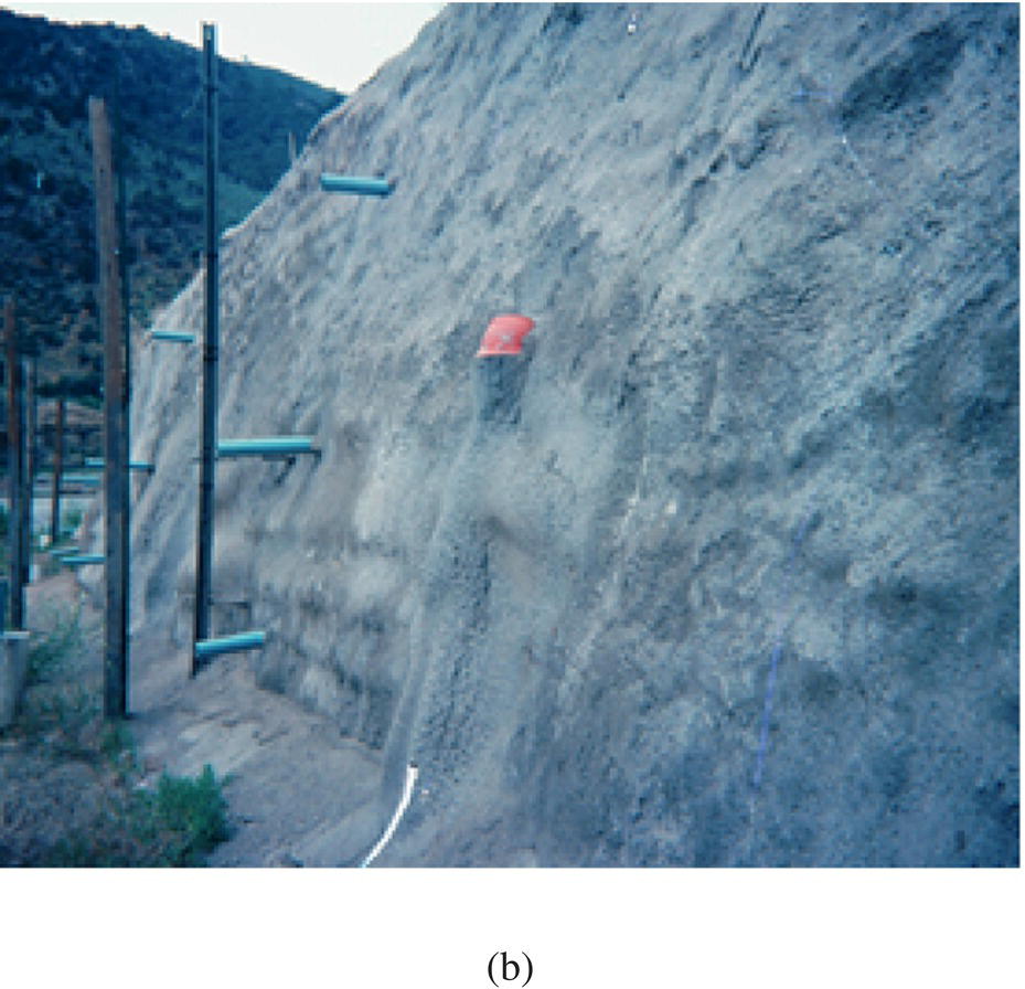
Figure 6.7 Exposed face of a wrapped‐face GRS wall covered with shotcrete: (a) application of shotcrete and (b) a completed wall face (rumor has it that the inspector remains trapped to this day) (courtesy of Bob Barrett)
Wire‐Mesh Wrapped‐Face GRS Walls (Permanent Form‐Work Walls)
Two completed wire‐mesh wrapped‐face GRS walls (permanent form‐work walls) are seen in Figures 3.24(b) and (c). The typical construction sequence of wire‐mesh wrapped‐face GRS walls (permanent form‐work walls) is illustrated in Figure 6.8, and can be described as follows:
- Step 1: Level the wall site and line up a series of continuous L‐shaped wire‐mesh on the ground surface along the planned location of the wall face.
- Step 2: Lay down a sheet of geotextile over the soil surface and the L‐shaped wire‐mesh by positioning it in such a way that about 1 m (3 ft) of the geotextile sheet is draped over the top of the wire‐mesh.
- Step 3: Backfill and compact the fill with conventional light‐weight earth‐moving equipment; fold the loose end of the geotextile sheet over the wire‐mesh and cover the soil surface.
- Step 4: Install another series of L‐shaped wire‐mesh over the top surface of the previous soil layer at a prescribed setback (setback would be zero for a vertical wall).
- Step 5: Repeat Steps 2 through 4 for subsequent layers until the design height is reached. For the final layer, the fold‐back length should be extended to at least 1.8 m (6 ft) behind the back of the wall face (preferably extend to the full length of the reinforcement layers) and covered with about 150 mm (6 in.) of fill.
- Step 6: If needed (e.g., for a more “permanent” wall), cover the exposed face of the wall with shotcrete (wet‐mixed concrete or mortar conveyed through a hose and pneumatically projected at high velocity onto the wall surface), bituminous emulsions, or other asphalt products to prevent weakening of the geotextile due to UV exposure and vandalism (see Figure 6.7).
Figure 6.8 Typical construction sequence of wire‐mesh wrapped‐face GRS walls (permanent form‐work walls)
To increase the bending stiffness of the wire‐mesh, many wall builders install struts to link across two ends of the L‐shaped wire‐mesh at a prescribed interval (say, every 16 in. or 0.4 m) in the longitudinal direction, see Figure 6.5(b), during backfill placement. In areas where climate permits, the setback area (if present) can be seeded to create a more natural‐looking wall face, see Figure 3.26(b) as an example.
Wrapped‐face walls of temporary and permanent form‐work differ in the following aspects:
- The L‐shaped continuous wire‐mesh used in permanent form‐work walls is left in place during construction, therefore construction time is substantially reduced. The left‐in‐place wire‐mesh also increases slightly the rigidity of the wall face, especially when struts are employed, and thus reduces the lateral wall movement.
- Permanent form‐work walls can use geogrid as reinforcement when much stiffer reinforcement is needed. When geogrid reinforcement is used, the wall face should be vegetated or wrapped by shorter length geotextile sheets.
- The windrows in the construction of temporary form‐work walls have been found unnecessary for construction of permanent form‐work walls, thus the construction time is reduced appreciably.
6.1.3 Full‐Height Precast Panel Facing GRS Walls
There are situations when a GRS wall with full‐height concrete facing is desired as it gives the perception of a stronger and more permanent wall. A full‐height concrete panel facing GRS wall, as shown in Figure 6.9, would serve that purpose. The wall can be constructed by two distinctly different methods: (i) construct a wrapped‐face wall first, then install full‐height precast facing panels over the wrapped‐face wall or (ii) install full‐height panels first, then construct a GRS soil mass behind the facing panels. In either method, the connection between the facing panels and the reinforced soil mass can be accomplished by face anchors (see Figure 6.9) installed in the reinforced soil mass during fill placement. The cast‐in‐place full‐height facing (CIP‐FHF) system described in Section 3.4.3 belongs to the first method, except that facing in the CIP‐FHF system is cast‐in‐place. The wall system, referred to as an independent full‐height facing (IFF) GRS wall, belongs to the second method. The IFF wall system has been described in some detail in Section 3.4.4.

Figure 6.9 Schematic cross‐sectional diagram of a full‐height facing panel GRS wall
The typical construction sequence of the IFF GRS wall is shown in Figure 6.10, and can be described as follows:
- Step 1: Level the wall site and excavate a shallow trench along the planned location of the wall face; the trench depth as suggested by the CTI is: depth (ft) ≅ [panel height (ft)/11] + 0.75.
- Step 2: Position precast facing panels in the trench at a design offset, and use a flow fill (a mixture of concrete sand, cement, and water at a flowable consistency) and a temporary bracing system (in front of the facing panels, see Figure 6.11) to prop the panel in position.
- Step 3: Backfill behind the wall facing, compact the fill in lifts to meet a specified minimum dry density, and lay down a reinforcement sheet on prescribed vertical spacing. For the fill within 1 m (3 ft) behind the facing panel, use only a hand‐operated compactor for compaction.
- Step 4: Install a row of face anchors (to connect the facing panel to the reinforced soil mass) at a prescribed interval along the longitudinal direction of the wall at a pre‐selected elevation.
- Step 5: Repeat Steps 3 and 4 by repeating the sequence of fill placement, fill compaction reinforcement placement, and face anchor installation as per construction plans until the design height is reached.
- Step 6: Remove the temporary bracing; place about 1 m (3 ft) of surcharge fill over the finished grade for at least 60 hours; remove the surcharge and loosen the nuts slightly on all anchor bars.
- Step 7: Back off the nuts between horizontally adjacent panels to align the facing panels as needed (see Figure 6.12).
Figure 6.10 Typical construction sequence of IFF full‐height precast panel GRS walls
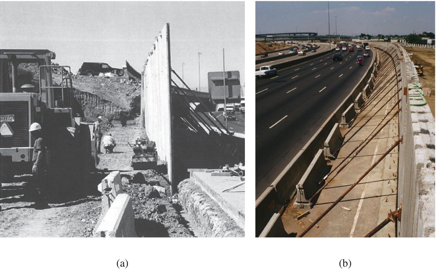
Figure 6.11 Construction of an IFF full‐height precast panel GRS wall: (a) facing panels situated in a shallow trench and (b) temporary bracing to prop up facing panels during construction (Ma and Wu, 2004)
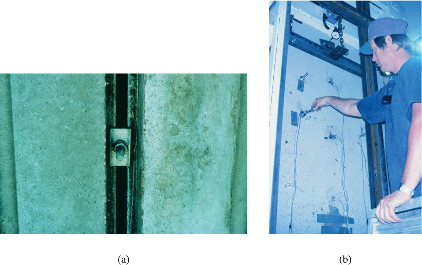
Figure 6.12 (a) Nut and bolt fastener between horizontally adjacent facing panels and (b) checking nut adjustment for alignment of facing panels in the laboratory (courtesy of Steve Foster)
As noted in Section 3.4.4, IFF full‐height precast panel facing GRS walls have two distinct attributes: (i) the face anchors used to attach the facing panels to the reinforced soil mass need to allow the facing panel to move outward during fill placement and compaction, so that the reinforcing function of the reinforcement can be mobilized, and (ii) there needs to be a mechanism for adjusting the inclination of the facing panel to align the facing panels in the final phase of construction; this attribute is essential for the aesthetics of the wall. Note that the second attribute is also needed when employing the first construction method (i.e., constructing the GRS wall first, then installing the facing panels).
6.1.4 Timber Facing GRS Walls
The typical construction sequence of timber facing GRS walls is shown in Figure 6.13, and can be described as follows:
- Step 1: Level the wall site and install the first row of timber logs along the planned location of the wall face; lay down the first sheet of geosynthetic reinforcement layer with a minimum 0.3 m (12 in.) fold‐back length (measured from the back of the timber facing).
- Step 2: Secure the first layer of geosynthetic reinforcement to the back of the first row of timber logs by using forming elements (treated plywood, fiberglass, or plastic; 3.5 in. in height for 6 in. × 6 in. timber logs facing) and nails.
- Step 3: Backfill to the top edge of the forming element; compact the fill; fold back the geotextile. Figure 6.14 shows reinforcement placement and fill compaction.
- Step 4: Install the next two rows of timber logs (or a row of timber blocks and a row of timber logs, as shown in Figure 6.13); place the next layer of geosynthetic reinforcement; secure the reinforcement layer to the newly placed timber logs (or newly placed timber blocks and timber logs) by using forming elements and nails; backfill and compact the fill to the design lift thickness (typically 0.3 m or 12 in.). Shimming of timber logs to maintain verticality is usually permissible.
- Step 5: Repeat Step 4 for all layers until the design height is reached. For the final layer, the fold‐back tail length should extend at least 2.4 m (8 ft) behind the back of the timber facing. All exposed fabric is often coated with a latex paint matching the color of the timber if alternating rows of timber logs and timber blocks are used.

Figure 6.13 Typical construction sequence of timber facing GRS walls
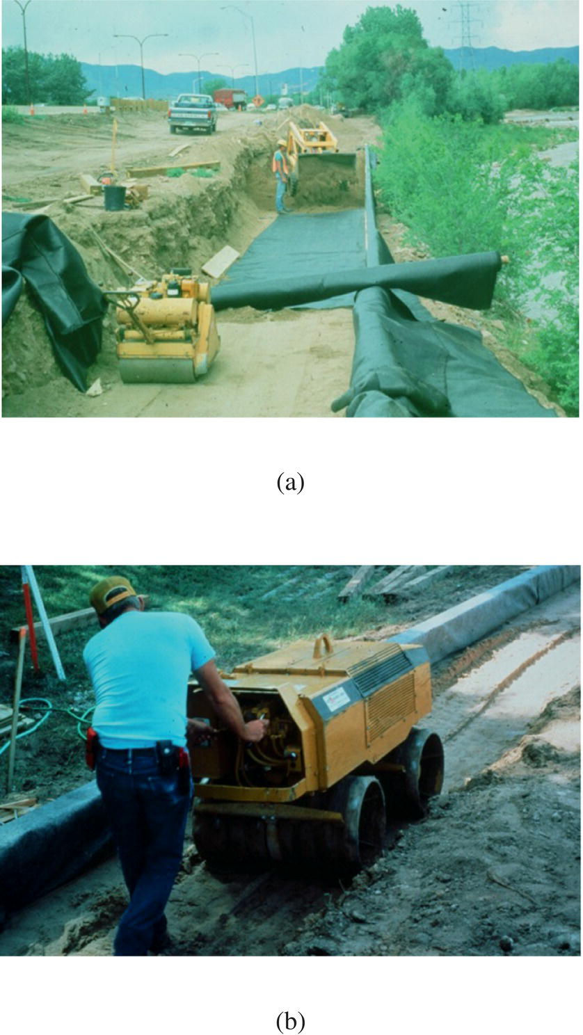
Figure 6.14 Construction of a timber facing GRS wall: (a) placement of geosynthetic reinforcement and (b) fill compaction (courtesy of Bob Barrett)
Figure 6.15 shows a timber facing GRS wall of which the facing comprises only timber logs; use of alternating rows of timber logs and timber blocks as illustrated in Figure 6.13 usually gives a more aesthetically pleasing wall face (see Figure 6.16).
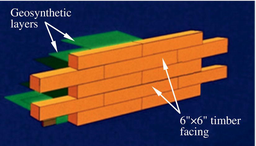
Figure 6.15 A timber facing GRS wall of which the facing comprises only timber logs (courtesy of Richard Andrew and Paul Macklin, in honor of John B. Gilmore)
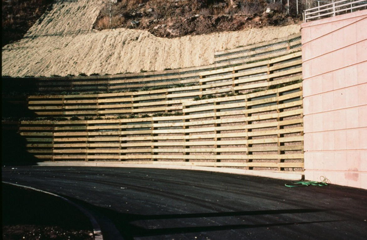
Figure 6.16 A timber facing GRS wall with alternating rows of timber logs and timber blocks (courtesy of Bob Barrett)
6.2 General Construction Guidelines and Specifications
The earthwork construction guidelines and specifications for GRS walls are essentially the same as those for conventional earth retaining structures. Additional guidelines and specifications related to facing and geosynthetic reinforcement, however, are unique for GRS and GMSE walls.
The construction guidelines and specifications given in this section are syntheses of those stipulated by the American Association of State Highway and Transportation Officials, AASHTO (2002), the National Concrete Masonry Association, NCMA (2002), the Federal Highway Administration, FHWA (Elias et al., 2001), the Colorado Transportation Institute, CTI (Wu, 1994), the Swiss Association of Geotextile Professionals, SAGP (1981), and the Japan Railways, JR (1998), as well as observations and experiences gained from construction of GRS walls and abutments by the author and his wall builder friends. Construction guidelines and specifications are usually project specific. The guidelines and specifications given here are for general reference only.
The construction guidelines and specifications presented in this section are grouped into six subsections: (i) site and foundation preparation, (ii) geosynthetic reinforcement and reinforcement placement, (iii) fill material and fill placement, (iv) facing, (v) drainage, and (vi) construction sequence. It is important to point out that backfill material, backfill placement, and drainage have often been identified as the three most important factors affecting the performance of GRS walls.
6.2.1 Site and Foundation Preparation
- Before construction, the site of a GRS wall should usually be graded to provide a fairly smooth and level surface. When feasible, the ground surface should be cleared of shrubs, trees, large rocks, stumps, etc. Depressions should be filled, soft spots should be dug out and replaced with the fill material to be used for the wall, and the site may need to be proof rolled.
- If seepage from beneath the base of the wall is of concern, a granular soil bed of nominal thickness (about 100–150 mm or 4–6 in.) may be formed at the base of the wall to alleviate potential seepage‐related problems.
- If the foundation soil contains a fair amount of frost‐susceptible soils (e.g., silt, silty tills, soils with clay content of 15–25%), excavate the foundation soil to at least the depth of extreme frost penetration (e.g., Figure 2.35) and replace it with a non‐frost‐susceptible soil.
- If the foundation soil is considered marginally competent, improvement of the foundation soil will likely be needed. A number of methods, such as deep vibration (for granular deposits) or drainage combined with surcharge (for cohesive deposits), may be employed for ground improvement. If improvement of the load‐bearing capability of the foundation soil is needed, a reinforced soil foundation may be formed in the top 1 m (3 ft) of the foundation soil by excavating the existing foundation soil and replacing it with well‐compacted granular fill reinforced with 3–4 equally spaced layers of a geosynthetic reinforcement of wide‐width tensile strength ≥ 70 kN/m or 4,800 lb/ft.
- If excavation is needed as part of the wall construction, it should be carried out to the lines and grades shown on the project grading plans. Overexcavation is generally not needed.
- In a stream environment, proper measures should be undertaken to protect the GRS wall from noticeable scour by water and abrasion by ripraps (e.g., Suaznabar et al., 2017).
6.2.2 Geosynthetic Reinforcement and Reinforcement Placement
- Geosynthetic products used as reinforcement for GRS walls are typically high‐tenacity woven geotextiles or geogrids specifically manufactured for soil reinforcement applications. Most guidelines stipulate that badly damaged or improperly handled geosynthetics should be rejected. Most geosynthetics tend to be weakened when exposed to direct sunlight or extreme temperatures for an extended period of time.
- Geosynthetic reinforcement is preferably installed under slight tension to mobilize more readily the reinforcing function. Nominal tension, although not mandatory in most guidelines, may be applied to the reinforcement with the aid of staples, stakes or hand tensioning until after the reinforcement is covered by about 150 mm (6 in.) of fill.
- In the direction perpendicular to the wall face, geosynthetic reinforcement is preferably of one continuous sheet. Overlapping of reinforcement along that direction should be avoided when feasible. Otherwise, adjacent segments of geosynthetic reinforcement should have sufficient overlap as specified in the construction plans. The “stronger” direction of a geosynthetic product (often the machine direction) should be oriented perpendicular to the wall face. It would be wise to select a geosynthetic product of which the stronger direction is its cross‐machine direction, and a choose roll width equal to the design reinforcement length plus the depth of the facing. In which case, the geosynthetic reinforcement can be installed by simply unrolling the reinforcement parallel to the wall face, hence expediting reinforcement placement.
- Tracked construction equipment is generally not allowed to operate directly over uncovered geosynthetic reinforcement. A minimum fill of 150 mm (6 in.) in thickness is commonly required before allowing operation of tracked vehicles over geosynthetic reinforcement. Turning of tracked vehicles should be kept to a minimum to prevent displacing the fill or damaging/displacing the geosynthetic reinforcement. Rubber‐tired equipment is usually allowed to pass over geosynthetic reinforcement, but only at a slow speed (less than 17 km/hr, or 10 miles/hr). Sudden braking and sharp turning should be avoided.
- For construction of concrete block GRS walls that rely on frictional resistance to gain facing stability, the front edge of the geosynthetic reinforcement layer should be nearly matching the front edge of the facing blocks to achieve the largest contact surface area.
- For GRS bridge abutments with relatively rigid facing, the geosynthetic reinforcement behind the facing is preferably wrapped. Wrapped geosynthetic reinforcement will help minimize fill sloughing and maintain the integrity of the fill material (preventing fill from falling into the gaps formed between the back of the abutment wall and the reinforced fill resulting from seasonal temperature change, see Figure 3.20). Wrapped return of at least 0.45 m (18 in.) and anchored at least 0.1 m (4 in.) into the fill material is recommended. Wrapped return of the top geosynthetic layer should extend as far as practical, 1.8 m (6 ft) minimum, for load‐bearing bridge abutment walls.
- For GRS bridge abutment walls, if the lateral earth pressure is expected to be very large, a compressible/collapsible layer (e.g., low to medium density expanded polystyrene) of approximately 50 mm (2 in.) in thickness may be installed over the backface of the abutment wall to relieve lateral earth pressure and minimize cracking of the wall (Monley and Wu, 1993).
- For concrete block GRS walls, installing reinforcement on every facing block to keep reinforcement spacing to a small value is generally recommended. Otherwise, secondary reinforcement (tails) (see Figure 6.3) alternated between full‐length reinforcement layers may be incorporated if strict adherence to the sequence of reinforcement placement can be assured during construction. The length of tails is typically 1 m (3 ft) behind the backface of facing blocks. The cross‐section of a typical concrete block GRS wall with tails in the upper portion and a truncated base in the lower portion is shown in Figure 6.17. Note that the cross‐section assumes that the existing earth behind the GRS wall is sufficiently stiff to maintain a stable near‐vertical face; otherwise, soil nailing with a top‐down construction procedure may be employed. The cross‐section also assumes that the fill material used in the GRS wall is free‐draining (see Section 6.2.3). If the fill material is considered only marginally free‐draining, geocomposite drainage strips with a high in‐plane permeability may be installed along the surface of the excavation to help with drainage of subsurface water (see Section 6.2.5).
Figure 6.17 Typical cross‐section of a concrete block GRS wall with alternating tails (shorter reinforcement layers) in the upper portion and a truncated base in the lower portion
6.2.3 Fill Material and Fill Placement
- Typical criteria of fill material in the construction of GRS walls are: 100% passing 4 in. (100 mm) sieve, 0–60% passing No. 40 (0.425 mm) sieve, and 0–15% passing No. 200 (0.075 mm) sieve (i.e., fines limit = 15%), with the plasticity index (PI) of the soil passing No. 40 sieve not exceeding 6. Fill material that meets these criteria is generally considered free‐draining. Note that some guidelines have suggested a much higher fines limit (e.g., 35% by NCMA, 2002).
- For wrapped‐face GRS walls that are not permanent in nature, deformation of the wall face is generally not a critical matter; fill materials of fines content of 30–50% have shown adequate performance, especially when the plasticity index does not exceed 8.
- The fill material should have a minimum angle of internal friction of 34°, with little or no cohesion, as determined by the standard direct shear test on the portion finer than No. 10 (2 mm) sieve, compacted to 95% of AASHTO T‐99, Methods C or D, and at optimum moisture content. Some guidelines (e.g., AASHTO, 2002, 2014) do not recommend using a friction angle of more than 40° in design due to a controversial concern that reinforcement loads may be underestimated. Usually no testing is required for soils of which 80% or more of soil grains (by weight) are 19 mm (3/4 in.) or greater.
- The fill material shall be substantially free of shale or other poor‐durability particles (e.g., shale, mica, gypsum) or organic material (usually should not be more than 1%). For permanent walls, the backfill should have a pH value between 3 and 9 for polyester reinforcement, and greater than 3 for polyolefin (polypropylene and HDPE) reinforcement. The pH limits may be relaxed to be between 3 and 11 for temporary walls.
- Strict attention should be given to ensure good compaction of fill in the construction of GRS walls, especially in areas near the wall face. Good compaction is especially important behind corners when they are present in a wall. Placement of fill material in the reinforced zone must meet the conditions specified in the construction plans. When it comes to improving performance of GRS, there is no substitute for higher soil stiffness (Wu et al., 2018). Provided the fill is sufficiently strong, all other factors (such as reinforcement stiffness, reinforcement spacing, and soil strength parameters) would have small influence on the stress–deformation behavior of GRS. Soil stiffness can be increased by proper selection of fill material type and better fill compaction.
- The fill material in the reinforced zone should generally be compacted within 2% dry of the optimum. If the reinforced fill is free draining (which is highly recommended for any type of GRS walls), the placement water content of the fill may be relaxed to within ±3% of the optimum. If the fill material contains an appreciable amount of fines (say, up to 35%), which should only be used if there are strong economic reasons for adopting the fill material and if a proven effective drainage system is installed, the placement moisture content of the backfill should generally be kept between the optimum and 4% wet‐of‐optimum.
- Compaction to a minimum dry density of 95% of the AASHTO T‐99 is recommended for non‐load‐bearing GRS walls and 100% for load‐bearing walls. A procedural specification is commonly used when a high percentage of coarse material (say, greater than 30% retained on ¾ in. or 19 mm sieve) prevents the use of the AASHTO T‐99 or T‐180 test methods. For procedural specification, 3–5 passes with conventional vibratory roller compaction equipment is generally adequate. Actual requirements on number of passes should be determined based on field trials.
- For compaction of a uniform fine to medium sandy fill material (say, with more than 60% passing No. 40 sieve), use of a smooth‐drum static roller or light‐weight walk‐behind vibratory roller should suffice. Use of larger vibratory compaction equipment for this type of fill material tends to have difficulty in achieving proper wall alignment, especially for light‐weight concrete block GRS walls.
- The fill material should be unloaded, spread, and compacted in a manner that will help minimize development of wrinkles or displacement of geosynthetic reinforcement. Placement of reinforced fill near the front of a wall should generally not lag behind the remainder of the wall by more than one compaction lift.
- Generally speaking, only hand‐operated light‐weight tampers or plates are allowed within 0.15 m (6 in.) of the back of a wall. For concrete block GRS walls, a unique tamping procedure suggested by Bob Barrett may be adopted to compact the fill within 15 mm (6 in.) behind the facing blocks. The procedure entails the wall builder placing one foot over the top of the block (of which the fill behind is being compacted) while using the other foot to forcefully tamp the fill.
- Selection of compaction machine is usually left to the contractor; sheepsfoot rollers, tamping foot rollers, or grid rollers are usually not to be used for compaction of fill material within the limits of the reinforced soil zone.
- When product specifications are adopted for fill compaction, field density and moisture testing of the reinforced fill should be performed on a regular basis during construction. A minimum frequency of one test per 1.5 m (5 ft) of wall height for every 30 m (100 ft) length of wall is common.
- At the end of each construction day, the last lift of backfill should be sloped away from the wall face to direct surface runoff away from wall face. Encroachment of surface runoff from adjacent areas toward the wall site should be prevented.
6.2.4 Facing
Dry‐Stacked Concrete Block Facing
- As a general rule, the masonry concrete blocks used in construction of reinforced soil walls are required to meet a minimum compressive strength of 14 MPa (2,000 psi) and a water absorption limit of 5%. Concrete blocks used in freeze‐thaw‐prone areas are required to be tested for freeze‐thaw resistance and survive 300 freeze‐thaw cycles without failure, as per ASTM C666. Properly shaped concrete caps (to facilitate drainage) should be placed over the top course of facing blocks to alleviate durability issues associated with freeze‐thaw. Facing blocks that may be exposed to spraying of pavement deicing agents are required to be sealed after construction with water‐resistant coating or be manufactured with coating or additives to increase freeze‐thaw resistance. Also, concrete masonry units (CMU) facing blocks or related products should meet the requirements of ASTM C90 and C140 for inspection, sampling, and testing. All facing blocks should be sound and free of cracks or other defects that may interfere with the placement of facing blocks or significantly impair the strength or permanence of a wall.
- Leveling of the first course of concrete facing blocks is especially important for proper alignment of wall face. Use of a string line set over pins from one end of the wall to the other will help with leveling the blocks.
- Most wall builders opt for constructing a concrete leveling pad under the first course of concrete blocks when the foundation soil is relatively incompressible and not susceptible to significant shrinkage/swell due to change in moisture. This measure is undertaken because a properly poured and leveled concrete pad can help speed up construction, ease the leveling process, and facilitate construction of a straighter wall. Other wall builders, however, have opted for installing a pad of compacted sand‐gravel (of approximately 75–150 mm or 3–6 in. thick and 450 mm or 18 in. wide) in place of a concrete pad. The sand‐gravel pad, being more flexible, tends to minimize cracking of the facing blocks.
- Facing blocks should be placed and supported as needed to ensure that their final position is vertical or battered as shown in the construction plans or in approved working drawings with a tolerance acceptable to the engineer.
- When light‐weight concrete blocks are used, it is recommended that the cores of the top 2 to 3 courses of facing be filled with concrete mix and (for bridge abutments) reinforced vertically with rebar. This measure is recommended because frictional resistance between these blocks alone may not offer sufficient frictional resistance to ensure connection stability due to low normal loads in these blocks.
- When a curved wall face is involved, blocks on the curve should be laid first as their alignment is more critical and less forgiving. Tight curves often require cutting blocks to fit or breaking off the block tail. A diamond‐tipped blade saw is convenient for cutting. The blocks should be laid from one end of the wall all the way to the other end to avoid laborious block cutting and fitting in the middle.
- If a wall involves sharp corners, as seen in Figure 6.18, a measure suggested by Bob Barrett is to fill the cores of corner blocks with concrete, along with No. 4 vertical rebar. It is very important that backfill in the area around the corner be compacted well to prevent opening up or cracking of blocks near the corner.
- After wall construction is complete, weed burner is commonly used to remove any visible excess geosynthetic reinforcement protruding from the wall face to improve aesthetics.
- Split‐face concrete blocks (blocks with a concave textured surface), manufactured by using a larger mold that holds two blocks face to face and broken apart at a precise time in the curing process, are often used as facing elements to help mask minor imperfections and slight lateral movement of the facing.
- The overall tolerance at the wall face of both vertical and battered walls should generally not exceed ± 30 mm (1.25 in.) over a 3 m (10 ft) distance (i.e., about 1%), and 75 mm (3 in.) total lateral movement at a maximum.
Figure 6.18 A tight corner of a concrete block GRS wall
Wrapped‐Face Geotextile Facing
- Compaction of fill material should be carried out with equipment that is less likely to damage the geotextile; generally, no machine compaction is allowed within 0.3 m (1 ft) of the wrapped face. Compaction lift thickness typically ranges from 0.2 m to 0.45 m (8 in. to 18 in.), with 0.3 m (12 in.) being the most common.
- If face deformation is to be kept to a minimum, reinforcement spacing of 0.15 m (6 in.) is recommended; this spacing has also been found easy to work with. Face alignment and fill compaction can be significantly improved with the use of external temporary forms. The use of scaffolds is usually necessary in front of the wall face for construction of walls taller than 1.8 m (6 ft).
- When making a windrow during construction (see Section 6.1.2), care should be exercised to avoid digging into the geotextile underneath or the wrapped face.
- Before applying shotcrete coating to the face of a vertical or near‐vertical wall, a wire‐mesh anchoring on the face is often needed to help the coating adhere to the wall face.
Precast Full‐Height Panel Facing
- Precast panel facing GRS walls comprise two major components: facing panels and reinforced soil mass. The two components are typically connected by metal anchors which are embedded in the reinforced soil mass during fill placement. Facing panels can be installed either before or after construction of the reinforced soil mass. For the latter, the reinforced soil mass usually needs to be wrapped at the face, but this is not necessary for the former. The lateral earth pressure exerted by the reinforced soil mass on the facing is generally much smaller in the latter than in the former, if the latter does not involve having to “force” the panels into the reinforced soil mass.
- A wide variety of shapes, thicknesses, colors, textures, and finishes of facing panels can be manufactured to accommodate the designer’s requirements. The exterior surface of precast concrete can vary from a highly ornamental exposed aggregate finish to a form face finish similar to cast‐in‐place.
- Precast‐concrete facing panels by themselves must be able to resist lateral loads directly imparted on them, as well as vertical loads resulting from their self‐weight. Other loads resulting from erection, impact, construction, and transportation of or on the facing panels should also be taken into account in design. It is important to evaluate the design, detailing, and erection of precast panels to avoid imposing unwanted loads on the panels.
- As in the IFF GRS wall described in Section 3.4.4, the base of the facing panel may be situated inside a narrow trench at a small batter with a temporary bracing system during construction. Flowable fill, a controlled low‐strength material, may be employed in the trench to help prop facing panels during construction. Flowable fill is a mixture of cement, water, aggregate, and sometimes fly ash in a runny weak concrete (slurry) consistency.
- There needs to be a mechanism in a panel facing GRS wall system to adjust inclination of the facing panel to align all panels before completion of the wall construction.
Timber Facing
- Timber used in timber facing GRS walls should be treated with copper chromate or an approved preservative to an acceptable level. The bottom row of timber needs to be treated for direct burial. The color of the timber may be green or brown, but usually not mixed. All exposed fabric is often coated with a latex paint matching the color of the timbers.
- Typical dimensions of timber logs used in construction are 150 mm × 200 mm (6 in. × 8 in.) or 150 mm × 150 mm (6 in. × 6 in.). Shimming of timber to help maintain verticality is usually permitted.
- Forming elements in the back of timber logs may be plywood (with a minimum nominal thickness of 25 mm or 1 in., treated with preservative to an acceptable level), fiberglass, plastic, or other approved material.
- Typical reinforcement used for timber facing GRS walls is nonwoven geotextile, although other types of geosynthetics satisfying design criteria may also be used.
- Nails used in construction should be 16d galvanized ring shank nails and should be driven onto the top and bottom of the timbers at no greater than 0.3–0.6 m (1–2 ft) intervals along the longitudinal direction of the wall.
- To improve connection strength on the top lifts, geotextile reinforcement may be wrapped around the timber then covered/protected with wooden panels, as suggested by Keller and Devin (2003).
- Compaction of backfill should follow project specifications; generally no compaction is allowed within 0.3–0.6 m (1–2 ft) of wall face.
Natural Rock Facing
- The height and slope angles delineated in the construction plans should not be exceeded without clear evidence that higher or steeper features will be stable.
- Rocks should be placed by skilled operators and should be placed in fairly uniform lifts.
- Care must be exercised when placing infill in the voids between rocks. The infilling needs to be as complete as possible.
6.2.5 Drainage
- Drainage design for surface and subsurface water, including seasonal change of drainage conditions, must be a component of a design. Inadequate drainage has been identified as one of the leading causes for poor performance (especially excessive deformation) of reinforced soil walls (Peters, 2017).
- Percolation of surface runoff into the backfill that is less than free draining during the service life of a GRS wall can lead to significant wetting‐induced settlement and reduced shear strength of the backfill. To reduce infiltration of surface runoff, the top surface of a GRS wall should be graded to direct runoff away from the wall. Interceptor drains on the back slope may also be used. Periodic maintenance may be needed to minimize surface runoff infiltration.
- For walls constructed below the free water level, dewatering may be needed to provide a dry working platform during construction. Many dewatering techniques (e.g., well points, horizontal drains, etc.) are available for this purpose, with the simplest technique being to construct perimeter trenches and connect them to sumps. In some cases, an impermeable barrier or other measures to minimize inflow of ground water into the wall site may be more effective than dewatering. Selection of the technique for ground water control during construction is usually left to the contractor.
- If the reinforced fill is not considered sufficiently free‐draining (coefficient of permeability ≤ 10–4 cm/sec or 0.15 in./hour), preventing ground water from entering the reinforced soil zone is usually more efficient than allowing water to come into the reinforced zone then attempting to drain it out. Installation of geocomposite drainage strips along the excavation limit may be employed (see Figure 6.19). Subsurface drainage within the reinforced soil zone and behind the wall face is generally not needed. However, when the backfill contains an appreciable amount of fines (say, more than 35% of fines), measures should be taken to minimize wetting/drying of the fill.

Figure 6.19 Geocomposite drainage strips installed at prescribed intervals over the face of the excavation limit
6.2.6 Construction Sequence
- For GRS bridge abutments that involve an upper wall (with the lower wall being a load‐carrying wall), it is better to construct the upper wall and compact the fill before placing the bridge girder on the lower wall. This sequence will produce a more favorable stress condition in the load‐bearing wall, increase load‐carrying capacity, and reduce settlement of the bridge abutment (Wu et al., 2006).
- Similarly, when constructing a GRS wall with rigid facing (e.g., high rigidity panel facing or cast‐in‐place concrete facing), it is better to construct the reinforced fill (commonly with a wrapped face) before constructing the rigid wall face. This will generally result in much reduced lateral earth pressure on the wall face and significantly smaller post‐construction settlement of the wall.
References
- AASHTO (2014). LRFD Bridge Design Specifications, 7th edition with 2016 Interims. American Association of State Highway and Transportation Officials, Washington, D.C.
- American Association of State Highway and Transportation Officials (AASHTO) (2002). Standard Specifications for Highway Bridges, 17th edition. HB‐17, American Association of State Highway and Transportation Officials, Washington, D.C.
- Elias, V., Christopher, B.R., and Berg, R.R. (2001). Mechanically Stabilized Earth Walls and Reinforced Soil Slopes, Design & Construction Guidelines. Report No. FHWA‐NHI‐00‐043, Federal Highway Administration, 394 pp.
- Japan Railway (JR) Technical Research Institute (1998). Manual on Design and Construction of Geosynthetic‐Reinforced Soil Retaining Wall. 118 pp.
- Keller, G.R. and Devin, S.C. (2003). Geosynthetic‐Reinforced Soil Bridge Abutments. Transportation Research Record 1819, Volume 2, 362–368.
- Kirsch, K. and Bell, A. (eds.) (2013). Ground Improvement. CRC Press, 511 pp.
- Ma, C. and Wu, J.T.H. (2004). Performance of an Independent Full‐Height Facing Reinforced Soil Wall. Journal of Performance of Constructed Facilities, ASCE, Vol. 18(3), 165–172.
- Monley, G.J. and Wu, J.T.H. (1993). Tensile Reinforcement Effects on Bridge‐Approach Settlement. Journal of Geotechnical Engineering, ASCE, Vol. 119(4), 749–762.
- National Concrete Masonry Association (NCMA) (2002). Design Manual For Segmental Retaining Walls, 2nd edition. J.G. Collin (ed.), 289 p.
- Nicholson, P.G. (2015). Soil Improvement and Ground Modification Methods. Elsevier, 455 pp.
- Peters, B.M. (2017). Design Considerations to Improve Performance of Geosynthetic Reinforced Mechanically Stabilized Earth Walls in Transportation Projects. M.S. Thesis, Department of Civil Engineering, University of Colorado Denver.
- Swiss Association of Geotextile Professionals (SAGP) (1981). The Geotextile Handbook, translation by US Bureau of Reclamation. Association of Geotextile Professionals, Denver, Colorado, 411 pp.
- Suaznabar, O., Huang, C., Xie, Z., Shen, J., Kerenyi, K., Bergendahl, B., and Kilgore, R. (2017). Hydraulic Performance of Shallow Foundations for the Support of Vertical‐Wall Bridge Abutments. FHWA‐HRT‐17‐013, Federal Highway Administration, Washington, D.C., 123 pp.
- Wu, J.T.H. (1994). Design and Construction of Low Cost Retaining Walls: The Next Generation in Technology. Publication No. CTI‐UCD‐1‐94, Colorado Transportation Institute, Denver, Colorado, 152 pp.
- Wu, J.T.H., Lee, K.Z.Z., Helwany, S.B., and Ketchart, K. (2006). Design and Construction Guidelines for GRS Bridge Abutment with a Flexible Facing. Report No. 556, National Cooperative Highway Research Program, Washington, D.C.
- Wu, J.T.H., Tung, C‐Y, Adams, M.T., and Nicks, J.E. (2018). Analysis of Stress–Deformation Behavior of Soil–Geosynthetic Composites in Plane Strain Condition. Transportation Infrastructure Geotechnology, Vol. 5(3), 210–230.