2.4
Shear Strength Testing – What is Wrong with the Direct Shear Test?
2.4.1 Introduction to Direct Shear Testing
Geotechnical texts often state that you should use some form of the triaxial test to determine the drained or undrained shear strength of soil. The direct shear test is dismissed as having an uncontrolled stress state due to rotation of principle stresses.
The direct shear test is simple, inexpensive, and doesn’t require an 18-inch thick uniform, high-quality sample (Lambe and Whitman, 1969, see page 120). If you are testing remolded samples, such as sands for compliance with Federal Highway guidance on MSE (mechanically stabilized earth) reinforced backfill, it’s easier to compact three similar samples of sand for a direct shear test than prepare three comparable samples for triaxial testing. Besides, FHWA publication FHWA-NHI-10-024, November 2009, recommends use of the direct shear or triaxial tests to evaluate the friction angle of reinforced fill material (specifying that it be at least 34 degrees, as determined by the direct shear test). Earlier versions of the FHWA MSE design guide required use of the direct shear test only, and didn’t even mention use of the triaxial shear test.
So the question is: What is wrong with the direct shear test and why worry about rotation of principle stresses? You might not recall from college days what rotation of principle stresses is, so I’ll refresh your memory.
2.4.2 Direct Shear Rotation of Principle Stresses
Principle stresses on a soil element are tension or compression stresses acting on planes that have zero shear stresses. In Figure 2.4.1, stresses σxx, σyy, σzz are normal stresses, meaning they act perpendicular to the x, y, and z planes. These normal stresses are principle stresses by definition when τxy = τyx = τxz = τzx = τyz = τzy = 0, that is when all of the shearing stresses on the x, y, and z planes are equal to zero. If you are like me, you have probably forgotten the stress subscript convention, so I’ll give it to you for clarity: σij is a stress where i is the direction of the normal to the plane where the stress acts, and j is the direction that the stress is acting. For example σxx is a stress acting on the plane that is perpendicular to the x-axis, and this stress is acting in the x-direction. The stress τxy (which we could call σxy, but I prefer using the tau symbol because it is a shearing stress) is acting on the plane that is perpendicular to the x-axis, and it is acting in the y-direction. When the subscripts i and j are the same, like xx, yy, or zz, the stress is a normal stress, and when the subscripts are different, the stress is a shearing stress.
Figure 2.4.1 Normal and shear stresses on soil element – 1987 sketch
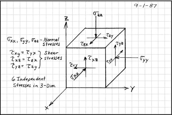
You might notice that Figure 2.4.1 is a hand-drawn and hand-lettered figure. This figure is from my 1 September 1987 class notes for advanced soil mechanics. This was a few years after the Cleveland Museum of Art installed a sculpture by Isamu Noguchi, and I went to see Noguchi and the accompanying exhibition of his work. Noguchi said that his work always included the H-factor. Afraid to ask the master himself, I asked my sculpture professor friend Carl Floyd, “What is the H-factor?” Carl told me that Noguchi’s sculptures were so perfect that he had been accused of making them by machine. So to prove that a human hand was involved, he always included a defect or chop mark on the sculpture’s surface to confirm that a human had made it. The H-factor meant that it was done by a human. Consider Figure 2.4.1 my inclusion of the H-factor to this work.
Figure 2.4.2 Direct shear test – rotation of principle stress when shearing

OK, let’s get back to the direct shear test. When you start a direct shear test, the vertical compression stress (i.e., σzz in the z-direction) is a principle stress because the horizontal plane perpendicular to the z-axis has no shear stress. Lateral bulging in response to the vertical sample loading causes lateral stresses on the sample (i.e., in the x-and y-directions). Lateral stresses in the x-and y-directions are the other two principle stresses at the beginning of the test because there are no shearing stresses on vertical planes through the sample. I might mention here that we can calculate the magnitude of the vertical normal stress in the z-direction at the beginning of the test, but we don’t know the magnitude of normal stresses in the x- and y-directions in a direct shear device. Some people assume that the lateral stress in the direct shear sample is (Ko) (σv), but hold on now, how do you know what Ko is before you run the test when you don’t know what the friction angle ![]() is prior to testing three samples and drawing the failure envelope. You need to know
is prior to testing three samples and drawing the failure envelope. You need to know ![]() to determine Ko = 1 – sin
to determine Ko = 1 – sin ![]() . Then again, how do you know that the direct shear sample is in an at-rest condition in the direct shear box? If the sample is clayey enough to be extruded into the direct shear box, there will probably be a gap between the sample and the sides of the box. Having a gap between the sample and the shear box will surely not replicate field at-rest conditions in the laboratory test. If the sample is a cohesionless sandy sample, it will likely have to be compacted in the laboratory in the shear box, again resulting in a different compacted lateral stress in the shear box than in the field. If you have an in situ sandy sample that is suitable for extruding into the shear box, or compact a sandy sample in a mold and then extrude it into the shear box, you will not likely replicate field at-rest conditions. During shearing of a direct shear sample there are serious lateral stress concentrations that are not quantifiable. So in conclusion, I prefer to say that we do not know what the lateral normal stresses are in a direct shear test.
. Then again, how do you know that the direct shear sample is in an at-rest condition in the direct shear box? If the sample is clayey enough to be extruded into the direct shear box, there will probably be a gap between the sample and the sides of the box. Having a gap between the sample and the shear box will surely not replicate field at-rest conditions in the laboratory test. If the sample is a cohesionless sandy sample, it will likely have to be compacted in the laboratory in the shear box, again resulting in a different compacted lateral stress in the shear box than in the field. If you have an in situ sandy sample that is suitable for extruding into the shear box, or compact a sandy sample in a mold and then extrude it into the shear box, you will not likely replicate field at-rest conditions. During shearing of a direct shear sample there are serious lateral stress concentrations that are not quantifiable. So in conclusion, I prefer to say that we do not know what the lateral normal stresses are in a direct shear test.
As the direct shear test starts, a lateral shearing force is applied to the soil sample, which generates shearing stresses on a horizontal plane through the sample. By definition, the vertical compression stress on the horizontal plane can no longer be a principle stress because shearing stresses on the horizontal plane are no longer zero. The principle stress direction has rotated from vertical, as shown in Figure 2.4.2. If the stress state in your foundation problem maintains the orientation of principle stresses in the vertical and horizontal directions, the direct shear test does not replicate the stresses generated during loading of your footing. Since the soil’s internal friction angle measured during a laboratory test depends on the state of stress generated during the test, it is important to replicate as closely as possibly your real-world problem’s state of stresses in your laboratory tests.
2.4.3 Use of the Direct Shear Test to Determine Internal Friction Angle, ![]()
Many soil material specifications include required values of the internal friction angle ![]() that must be equaled or exceeded. An example is the FHWA mechanically stabilized earth (MSE) wall reinforced backfill, which is specified to have an internal angle of friction equal to or greater than 34 degrees. These types of specifications have generated a problem in the industry and considerable confusion among engineers, contractors, owners, and yes I regret to include, lawyers. What am I talking about? Didn’t you think that the internal friction angle of a given soil was a fixed, characteristic soil property?
that must be equaled or exceeded. An example is the FHWA mechanically stabilized earth (MSE) wall reinforced backfill, which is specified to have an internal angle of friction equal to or greater than 34 degrees. These types of specifications have generated a problem in the industry and considerable confusion among engineers, contractors, owners, and yes I regret to include, lawyers. What am I talking about? Didn’t you think that the internal friction angle of a given soil was a fixed, characteristic soil property?
Where do I start? First I’ll answer the question directly, and then I’ll explain. The answer is no, the internal friction angle ![]() is not a characteristic soil property. The value of
is not a characteristic soil property. The value of ![]() depends on the shear strength tests used, how the tests are run (saturated versus unsaturated, slowly versus rapidly, drained versus undrained, to name a few), density and fabric of the soil in the lab versus in the field, stress state in the lab versus in the field, and shearing strains generated in the lab versus the actual strains experienced in the field.
depends on the shear strength tests used, how the tests are run (saturated versus unsaturated, slowly versus rapidly, drained versus undrained, to name a few), density and fabric of the soil in the lab versus in the field, stress state in the lab versus in the field, and shearing strains generated in the lab versus the actual strains experienced in the field.
Before we go on, I’d like to explain what those tables of soil types with listed friction angles in standard geotechnical references mean. I know that they surely look like prescriptive internal friction angles for listed soil types. For an example, let’s go to page 107 of Terzaghi and Peck’s 2nd edition of Soil Mechanics in Engineering Practice and look at their Table 17.1 (Terzaghi and Peck, 1967). Representative values of internal friction angle ![]() are given for round-grained uniform sands, angular-grained well-graded sands, sandy gravels, silt sand, and inorganic silt. Values given in Terzaghi and Peck’s Table 17.1 (Terzaghi and Peck, 1967) for each soil type are listed for both the loose and dense states. These reported drained shear, friction angle values are peak values for effective vertical stresses less than 10 000 pounds per square foot. Although not discussed, it is likely that these internal friction angles are from direct shear tests with vertical effective stresses greater than about 500 to 1000 pounds per square foot (Note: I know that Terzaghi preferred triaxial shear tests, but my experience is that most reported friction angle values in early texts are from direct shear testing). At the time these table values were generated, it was not common to determine high-strain, residual values of internal friction angle, and so many engineers just took the friction angle from the loose state as the residual, high-strain value. Many laboratories doing soil testing in the 1950s and 1960s were using direct shear equipment that did not have the capability of measuring shear strength values beyond the peak value. Also at this time the values of
are given for round-grained uniform sands, angular-grained well-graded sands, sandy gravels, silt sand, and inorganic silt. Values given in Terzaghi and Peck’s Table 17.1 (Terzaghi and Peck, 1967) for each soil type are listed for both the loose and dense states. These reported drained shear, friction angle values are peak values for effective vertical stresses less than 10 000 pounds per square foot. Although not discussed, it is likely that these internal friction angles are from direct shear tests with vertical effective stresses greater than about 500 to 1000 pounds per square foot (Note: I know that Terzaghi preferred triaxial shear tests, but my experience is that most reported friction angle values in early texts are from direct shear testing). At the time these table values were generated, it was not common to determine high-strain, residual values of internal friction angle, and so many engineers just took the friction angle from the loose state as the residual, high-strain value. Many laboratories doing soil testing in the 1950s and 1960s were using direct shear equipment that did not have the capability of measuring shear strength values beyond the peak value. Also at this time the values of ![]() were reported to be the same for wet and dry samples.
were reported to be the same for wet and dry samples.
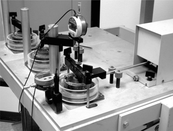
Figure 2.4.3 Direct shear device
2.4.4 The Direct Shear Test – Details
The direct shear test is still the commercial laboratory test of choice for testing granular soils for most geotechnical applications. The ASTM standard for direct shear testing is ASTM D 3080, and the AASHTO standard for this test is T-236 (AASHTO, 2006). According to AASHTO, T-236 is similar, but not technically identical to ASTM D 3080. The only difference that I’m aware of between ASTM D 3080 and T-236, is sample saturation. The AASHTO tests are all required to be saturated prior to testing, and the ASTM direct shear tests can be dry, moist, or saturated, so long as the engineer specifies test conditions that replicate field conditions.
The direct shear test is intended by specification to be a consolidated drained shear test, although the rate of shearing of fine-grained samples has to be appropriately slowed to prevent generation of excess pore water pressures during testing.
The standard test is conducted at a controlled rate of horizontal shearing on a sample held between a top and bottom portion of a shear box, see Figure 2.4.3. The shear plane is assumed to be a single horizontal failure surface generated between the top and bottom sections of the shear box. Observation of the actual shearing surface after conducting a direct shear test indicates that it is not planar, but more of a “concave up” curved surface. The curved nature of the actual failure surface in the direct shear test is explained by rotation of principal stresses that changes the orientation of sample failure stresses as the test progresses, thus causing changes in the orientation of the failure surface.
The direct shear test can be modified to apply gravity-actuated fixed horizontal loads to evaluate creep properties of clayey soils, but such tests are considered to be special, engineering tests and are not covered by standard ASTM or AASHTO specifications.
Results of a single direct shear test are not often used alone, but rather three or more tests at varying vertical consolidating stresses are performed, and the peak shear strength values from these tests are plotted on a graph of vertical stress (on the x-axis) versus shearing stress (on the y-axis) to determine the soil’s internal friction angle. The soil’s friction angle is defined as the slope of the line through the plotted shear stress versus vertical stress points, see Figure 2.4.4.
Figure 2.4.4 Direct shear plot – three tests
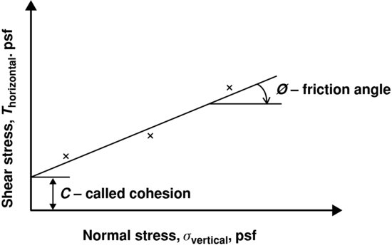
Please note that since you don’t know what the principle stresses are at sample failure, you cannot plot Mohr’s circle of stresses for the direct shear test. Also note that since the direct shear test measures horizontal deflection during loading and not horizontal shearing strain, a plot of stress versus strain cannot be generated from this test. This is a significant drawback, because determination of the shear modulus from a shearing stress versus shearing strain plot would be useful. Attempts to design a square direct shear box to allow determination of shearing strains have not been successful due to non-uniform distribution of strains on the shearing plane, and changes in stress orientations during the test. Yes, it’s the old rotation of principal stresses issue again.
Since by both ASTM and AASHTO standards, the design engineer must specify test conditions to replicate field conditions, there can be no such thing as a standard direct shear test. You can’t call up the lab and order one like a cheeseburger. You need to specify the vertical stresses for the three test points, when to consider the vertical consolidation to be complete, when to saturate the shear box, and what shearing rate of loading to use. Although not included in some soil laboratories’ test reports, you should require plots of vertical dial gauge readings both during consolidation of the sample and during shearing of the sample. You should also request a plot of lateral deformation versus lateral shearing stress for all tested samples. In addition to the vertical stress versus horizontal shearing stress plot of points used to determine the internal friction angle, you should also have laboratory data for the dry unit weight and degree of saturation of each sample both before and after shear testing.
2.4.5 How Can the Direct Shear Test Go Wrong?
There are likely dozens of things that can go wrong in a direct shear test, but I’ll focus on our part first, the engineer’s issues. I mentioned it before, but I’ll say it again, you can’t order a direct shear test from a laboratory like you order a ready to eat cheeseburger from McDonald’s. You have to specify the details of the test, the consolidation vertical stresses, shearing rate, sample saturation, and so on. I suggest you closely review ASTM D 3080 or AASHTO T-236 before you send your direct shear order to the laboratory.
One example of misapplication of the direct shear test that sticks in my mind is one that resulted in a costly failure for a local engineer (not me). The fill soil proposed for backfill was an on-site clay shale material. A good granular backfill may have been an easy choice, but costs were a significant project factor and the engineer thought, “if the direct shear test gives me a high enough friction angle I can design around it.” The engineer had samples of on-site clay shale material delivered to a soils laboratory and he asked for a direct shear test. He didn’t specify any of the required details of the test to simulate anticipated on-site conditions. The laboratory technician did his best and guessed that since this was going to be a fill soil application that the test samples should be compacted to 95% standard Proctor at 2% below optimum moisture content. The direct shear test was done on three samples using vertical stresses that seemed good to the laboratory technician. The samples were run “saturated” in that the laboratory technician filled the chamber around the direct shear samples with water immediately before shearing. The result of this test was a reported friction angle of 45 degrees.
Upon review of the direct shear test results and after checking his college textbook, the engineer called the soils laboratory to suggest that the test was in error because a clay shale material has a friction angle less than 45 degrees. He questioned the laboratory technician about saturating the samples, and recommended that he wait a while for water to soak in before shearing the clay shale soils. The engineer then directed the technician to rerun the direct shear tests. The laboratory technician reran the tests exactly the same as before, but he added water and waited two hours before shearing each sample. When asked later why he waited two hours for the water to soak into the clay shale samples, he said that he wanted to finish the tests in a single work day. Results of the second set of direct shear tests was a reported friction angle of 24 degrees. Upon receiving results of the second set of direct shear tests, the engineer was satisfied that now he had a reasonable friction angle value for design. He designed the fill structure using the 24 degree friction angle, and about a year later the structure failed. During forensic analyses of the failed structure, direct shear tests were performed on the clay shale material, and several sets of samples were soaked until the vertical dial gage indicated that swelling had stopped, which took about 36 hours per sample. The reported friction angle of this third set of tests was 11 to 12 degrees.
What can we learn from this application of the direct shear test to design? If the vertical confining stresses are too high, that is they are much higher than will be experienced in the field, the indicated swell during saturation of samples can be reduced or eliminated. What can be a real problem is if two tests do swell and the third one has a high vertical stress and doesn’t swell. The result is that the soil will swell in the field but not in the test. Another problem with excessive vertical test stresses is that the first test and second test may dilate during shearing, but the third test does not dilate due to high stresses. The result is three points that don’t come close to a straight line. Time is very important in direct shear tests of clays and clay shales. If the samples don’t soak long enough to reach equilibrium, they will not fully soften. Also if these highly impermeable samples are sheared too rapidly, they will generate excess pore pressures and will not represent the consolidated drained conditions that you expect from a direct shear test.
2.4.6 Evaluating Results of Direct Shear Tests
When evaluating the results of direct shear tests, your main concern has to be uniformity of the three test specimens. If they are not identical, you cannot draw a line through the three test results and compute shear strength parameters, c and ![]() . Shear strength of the three test specimens used in the direct shear test should be a function of vertical effective stress and nothing more. If other unrecognized variables are present that affect the shear strength of one or more of the test samples, the shear strength parameters developed by the test are affected in undefined ways.
. Shear strength of the three test specimens used in the direct shear test should be a function of vertical effective stress and nothing more. If other unrecognized variables are present that affect the shear strength of one or more of the test samples, the shear strength parameters developed by the test are affected in undefined ways.
Check that the dry unit weight of all three samples is equal (or very close to equal) prior to applying the vertical loading. Dense samples are stronger than looser samples. If you have to fit a line through three points, weigh your decision based on dry unit weights.
Check that all three samples are handled and processed the same. For remolded soils, all three samples should be processed and compacted by the same process. For in situ samples, they should be as similar as possible, and they should all be handled in exactly the same way for each test. Changes in compacting samples in the shear box or in handling and inserting samples into the shear box will cause disturbance and affect soil fabric, which changes the soil shear strength.
Check to be sure that all three samples have reached equilibrium after consolidating and after flooding the shear box. After flooding, the vertical displacement dial gage readings should be taken until the sample stops moving. Make sure the laboratory technician does not flood the samples and test immediately, or flood the samples and wait 15 minutes. It is not the lab technician who should define the correct sample soaking time, it should be the sample! Guidance for consolidation and soaking times are given in ASTM and AASHTO standards.
The lab should report the vertical dial gage readings during sample soaking and during shearing. The lab should also plot horizontal shearing stress versus lateral deflection for your study and inclusion in the geotechnical report. In a constant rate of shearing test, the test should be run until a constant residual shearing stress is achieved. If the lateral displacement reaches 10% of the sample diameter, the test should be stopped to prevent excessive reduction of the sample’s shearing cross-sectional area. For a standard test, pick the peak shearing stress for construction of the shearing stress versus normal stress plot, see Figure 2.4.4. If you need a residual shear strength value, you can plot the shearing stress at maximum deflection, but I doubt you would have a true high strain residual value (Duncan and Wright, 2005, page 50), or you can do a stress reversal loading where the sample is sheared back and forth until a high strain residual shearing stress value is reached. I know what you’re thinking, “What about rotation of principle stresses when you reverse shearing directions back and forth several cycles?” I know it’s not the best large strain test, because it is highly unlikely to represent field conditions, but it is better than nothing and it does provide residual values that approximate high strain shear strength.
2.4.7 Concluding Remarks about the Direct Shear Test
The direct shear test is cost effective and useful when you don’t have enough identical soil samples to perform triaxial testing. The direct shear test has several pitfalls and can be misleading if you are not careful when specifying test conditions and interpreting test results. Like everything else in geotechnical engineering, the direct shear test is OK if you use it appropriately. Unlike many other standard ASTM or AASHTO tests, the direct shear test requires several test conditions be specified by the project geotechnical engineer. This is because the direct shear test conditions should simulate or replicate field conditions for the project specific application as closely as possible (within reason). This required interaction between the geotechnical engineer and the laboratory is often misunderstood or ignored by both the engineers and laboratory personnel. Rotation of principle stresses will occur in your direct shear tests, but remember that some data is better than no data. If you are careful and don’t believe that direct shear values of c and ![]() are exact models of your soil’s shear strength, you will be able to use direct shear data in your analyses and designs.
are exact models of your soil’s shear strength, you will be able to use direct shear data in your analyses and designs.
References
Standard Method of Test for Direct Shear of Soils Under Consolidated Drained Conditions, AASHTO Designation T 236-03 and ASTM Designation D 3080-72 (1979).
Duncan, J.M. and Wright, S.G. (2005) Soil Strength and Slope Stability, John Wiley & Sons, Inc. Direct Shear Test, pp. 50–53.
Lambe, T.W. and Whitman, R.V. (1969) Soil Mechanics, John Wiley & Sons, Inc. , 553 pages.