3.4
Bearing Capacity of Shallow Foundations
3.4.1 Background and History of Bearing Capacity
In the era before Karl Terzaghi's bearing capacity equation was introduced in the United States, engineers went to their local building codes to determine what the allowable bearing pressure was for design of their foundations. If they were working outside of a major metropolitan area, where no local experience or building codes existed, they had to refer to general texts on “foundation soils.”
In my library, I have a textbook, Foundation Soils, published by the International Textbook Company in 1909 with no author noted, which I find to be weird. This 1909 engineering text suggests that foundation soils should first be examined to determine their character, be it rock, gravel, sand, or clay.
They go on to say, “Where no test of the sustaining power of the soil is made, different soils, excluding mud, at the bottom of the footings shall be deemed to sustain safely the following loads to the superficial foot: soft clay – 1 ton per square foot; ordinary clay and sand together in layers, wet and springy – 2 tons per square foot; loam, clay or fine sand, firm and dry, 3 tons per square foot; very firm, coarse sand, stiff gravel or hard clay – 4 tons per square foot.” They strongly suggest performing a full-scale footing load test. They state that a large building or important structure where the designer wants a greater bearing capacity than given in the list above, a load test is to be performed. In the 1909 text, they give a detailed description of a full-scale footing load test to determine the load versus settlement curve of the foundation–soil system.
Before introducing the bearing capacity equation in his 1943 textbook, Theoretical Soil Mechanics (Terzaghi, 1943), Terzaghi discusses a footing's load settlement curve and how to determine a footing's failure loading from the load test curve. Then Terzaghi goes on to suggest that the bearing capacity equation is a simplified method of estimating the failure loading of a shallow footing. He discusses a general shear failure and a local shear failure of foundation soils, indicating that excessive settlement of loose sands results in a local failure before a general shear failure can be mobilized.
Early geotechnical texts such as Soil Mechanics in Engineering Practice by Terzaghi and Peck, first printed in 1948, include charts that give allowable bearing pressures for 1 inch of settlement for footings of varying widths on sands of varying density. The point of this review of early geotechnical publications is that bearing capacity was not limited to a discussion of soil strength, as it often is today. Early pioneers of geotechnical practice knew that performance of foundations was directly related to foundation settlement. A foundation that was load tested and designed for a high allowable bearing pressure may not experience a general shear failure, but if the footing settled excessively, it failed to support the structure properly.
3.4.2 Allowable Bearing Pressure
One engineer told me, “When I was in school, the professor said that you find the soil's cohesion and friction values, plug them into the bearing capacity equation, divide by a factor of safety of three and presto, you have the allowable bearing pressure for foundation design. Simple enough, game-set-match, I'm ready to design my footings.”
Another engineer said, “After I got out of school and started working as a staff geotechnical engineer, I never used the bearing capacity equation. We related standard penetration blow counts to approximate allowable bearing pressures, sized footings and calculated footing settlements for various loading cases, what happened to the three N's bearing capacity equation?”
I was in a meeting with an architect and structural engineer of a building that had experienced excessive foundation settlements requiring underpinning. The structural engineer was genuinely confused. He said, “All of my footings were sized for less than the recommended allowable bearing pressure. How could the footings fail if I didn't overload them?”
“It's simple,” I told him, “The footings were built on dry, loose fill that was contaminated with clay balls. The fill soil settled when it got wet. When the foundation support soil goes down, the footings go down, no matter what bearing pressures they were designed for. It's settlement that counts, not bearing capacity.”
No matter how hard I try to explain the importance of foundation settlement under loading, architects and structural engineers want an allowable bearing capacity value to design their foundations. In all requests for a geotechnical proposal from architects and structural engineers they specifically include in their geotechnical requirements the need for a recommended allowable foundation bearing pressure. It is always an absolute necessity. They even include a list of geotechnical requirements as an appendix A to their contract with the geotechnical engineer, so the geotech has no choice but to provide a value of allowable bearing pressure in the geotechnical report or be in violation of a signed contract.
What to do? First, I strongly recommend that you do not violate your contracts! Secondly, I recommend that the allowable bearing pressure value that you give in your geotechnical report be based on acceptable settlement values. Do not recommend an allowable bearing pressure for footing design based on the ultimate bearing pressure determined by the bearing capacity equation without consideration of settlement. Thirdly, I suggest you talk with your clients about performance of their structures. What settlements are acceptable, and what maximum settlement constitutes their definition of structural failure.
The simplest procedure I know for finding an allowable bearing pressure for design of spread footings on sandy soil (although I also use it for low-plasticity silty clays) is to divide the average blow count N by five (since the footings are not sized at this point, I average N over 5 to 6 feet to start and then after I have a preliminary footing size I repeat the process by averaging over 1B depth for square footings and 2B for long footings), and interpret the result as kips per square foot for ½ inch settlement.
Equation 3.4.1 is an experienced-based allowable bearing capacity equation that is similar to early Meyerhof recommendations; see Meyerhof (1956), Equation 7c, page 5. Equation 3.4.1 works reasonably well for footings about 2 to 4 feet wide that bear at depths of about 2 to 3 feet below grade in soils with SPT blow counts of about 5 to 20. This equation comes with an admonition, which is actually an early “rule of thumb,” that soils with blow counts below 4 are “un-buildable” (that is, you need to improve the soil or use deep foundations). For the same 2 to 4 foot wide footings bearing on soils with blow counts of 25 to 50, Equation 3.4.1 changes because you divide N by four to get an allowable bearing pressure in kips per square foot for ½ inch settlement, as shown in Equation 3.4.2.
For footings more than 4 feet wide, there are equations and charts in textbooks that give you allowable bearing pressure values versus SPT blow count N for 1 or ½ inch settlement. For a selection of these charts and graphs, I suggest Meyerhof's 1984 book (Meyerhof, 1984) (although it is quite hard to find), or you could check standard geotechnical texts such as Peck, Hanson, and Thornburn (1974) or Joseph Bowles (2005).
Although dividing the standard penetration blow count N by 4 or 5 is the easiest way I know to find an allowable bearing pressure, the second easiest standard practice procedure is to use a design chart developed by my friend Ralph Peck. Dr. Peck's chart was originally included in the Peck, Hanson, and Thornburn text of 1953 (Peck, Hanson and Thornburn, 1953). A large, nearly full-page copy of this chart is given on page 159 of T.H. Wu's 1966 textbook (Wu, 1966). Both of these early text books can be purchased used on the Internet. Dr. Peck and his fellow authors revised the bearing capacity chart in their second edition of 1974 on page 309 (Peck, Hanson and Thornburn, 1974) to include footings of varying embedment depths. These bearing pressure charts are well known to be conservative, so I use them with an assumed settlement of 0.5 inch rather than their published 1.0 inch settlement value, as suggested by Joseph Bowles in his third edition text (Bowles, 1982).
Joseph Bowles in his fifth edition text (Bowles, 1996) gives similar charts with higher bearing pressures than Peck or Meyerhof. In Bowles’ first edition text (Bowles, 1968) for footings 4 feet wide or less, Bowles divides N by 2.5 to get an allowable bearing pressure in kips per square foot for 1.0 inch settlement, which is essentially the same as dividing N by 5 for 0.5 inches of settlement.
All of the SPT-derived bearing pressure relations described above may be used for preliminary design, although modern practice uses advanced analyses to determine final allowable bearing pressure values. Oh, I might remind you that early references to SPT blow count N are likely N45 or N55 values.
3.4.3 How Structural Engineers Use Allowable Bearing Pressures
When structural engineers design building column footings using the concrete code, ACI-318-05, they use the allowable bearing pressure to size the footing using service loads (unfactored loads that the column is expected to regularly support). For example, if the service dead load is 150 kips and the service live load is 250 kips, and you recommend a net1 allowable bearing pressure of 4 kips per square foot, the structural engineer will add 150 plus 250 for a total of 400 kips and divide by 4 kips per square foot to get 100 square feet. Then he will take the square root of 100 to find a footing size of 10 feet by 10 feet square.
After the structural engineer has a footing size, he or she uses load factors of 1.2DL and 1.6LL to determine the design bearing pressure as follows: 1.2 × 150 kips = 180 kips, 1.6 × 250 kips = 400 kips, and 180 kips plus 400 kips equals 580 kips. The design factored bearing pressure for determining the footing thickness and the reinforcing steel is 580 kips divided by 100 square feet equals 5.8 kips per square foot.
If your ultimate bearing capacity was three times the allowable value (i.e., a factor of safety of 3), then it was equal to 3 × 4 kips per square foot or 12 kips per square foot. If the structural engineer's statistically derived, load-factored design bearing pressure ever actually occurred, you would still have a soil bearing factor of safety of 12 ksf divided by 5.8 ksf equal to a factor of safety of 2.07.
Here is a plan of action for determining the allowable bearing pressure to recommend in your geotechnical report that will provide the structural engineer what he needs for footing design, while still considering the affect of footing settlement on structural performance:
1. After studying the site geology, topography. and history, design a site investigation plan that adequately characterizes the site for its required uses. Remember the graded approach. Such an investigation may include test borings, cone penetration tests, pressure meter tests, model or full-scale load tests, and geophysical tests. Findings of field tests might not match what you expected in your plan, so be flexible and anticipate that plan adjustments will be required. Plan adjustments may require additional field or laboratory tests so you should make your client aware that a second phase of testing may be required if his site holds geologic or manmade surprises, such as fill.
2. Conduct laboratory testing that is designed to provide data required for project specific analyses, again remember the graded approach. Generic testing plans often fall short of providing needed data for your analyses. Use of multiple levels of correlations based on a few SPT, CPT, or PI tests often introduces unacceptable uncertainty into your analyses that are incorrectly interpreted by your client and by other consultants as excessive conservatism.
3. Obtain a list of estimated column and footing loads from the project structural engineer. If he won't give you a table of values, at least get a minimum and a maximum value, and an estimate of how closely spaced these potential differential settlement parts of the structure may be.
4. Prepare several profiles across the site and select a critical profile for your allowable bearing pressure analysis. The critical profile should have the worst boring included, even if you are not sure that it may occur at the location of the largest column or wall loading. When preparing these profiles, make corrections to SPT or CPT data as required by standard practice in your area or refer to federal highway, state highway, US Army Corps of Engineers, or other standard guides, documents, or publications.
5. Determine or estimate the bottom of footing elevation. In most parts of the United States footing bottoms are required to be between two and five feet below the ground surface. Don't forget that your site may be sloped and your footing elevations will vary accordingly. Depths of footings below finished grade are often specified in local building codes. If there is no local building code, footing depths used are often standard practice values set by local engineers and architects.
6. Assuming that the zone of influence of the building footings will be twice the footings’ width, approximately five to 15 feet below the bottom of the footing bearing level, average test boring SPT blow counts in the zone of influence for the worst and best borings on the critical profile.
7. Using the average blow counts corrected for depth and for hammer energy, calculate the foundation preliminary allowable bearing pressure in kips per square foot by using N70/4 or N70 /5 as discussed above.
8. Calculate the approximate sizes of the largest and smallest adjacent footings by dividing their column service loading in kips by the allowable bearing pressure in kips per square foot.
9. Using the footing size and service load-bearing pressure, calculate the settlement of the adjacent large and small footings. See Sections 3.1, 3.2, or 3.3 for methods of calculation of footing settlements. If your project is a standard commercial project supported on granular or unsaturated soils, I would use the Schmertmann method or the Janbu equation, S = μo μ1 q B (1 − μ2) / Es (see Section 3.2 or check out Bowles’ first edition textbook, pages 91 and 92).
10. Unless you have specific direction from the project structural engineer, I would make sure that the maximum calculated differential settlement is ½ inch or less. I know that both geotechnical and structural engineers frequently bandy about a total or differential settlement of 1 inch in discussions, but it is my experience that these 1 inch numbers are not supported by measurements of actual structures.
11. If your calculated differential settlement is not less than ½ inch, go back to step 7 and adjust the allowable bearing pressure. Redo the calculation until you have an acceptable differential settlement, or if the differential settlement is excessive for all reasonable footing sizes then develop alternate foundation recommendations, such as soil improvement, a mat, combined footings, micro-piles, augered piles, driven piles, drilled shafts, and so on.
If you insist on using one of the standard Terzaghi, Meyerhof, or Hansen bearing capacity equations, which in some circles is referred to as the three N's equation, you can substitute the allowable bearing pressure in Step 7 by one-third of the ultimate bearing capacity qultimate calculated by the bearing capacity equation. Bearing capacity equations are covered very thoroughly in almost any geotechnical text book that you may pick up, so I will not repeat that material here. I would add two notes of caution when using bearing capacity equations published in older books. Back in Terzaghi's day, let's say the 1940s and 1950s, it was standard practice to define the footing width as 2B, that is B was equal to one-half of the footing width. In later textbooks this early convention was changed to make the entire footing width equal to B. Whatever book you use for the bearing capacity equation, please make sure to check the definition of B. My second caution to you is to check values calculated for the third bearing capacity factor Nγ. In earlier bearing capacity references, the values calculated for Nγ were not properly bounded. In other words, calculated values of Nγ were much too large. I suggest you refer to a modern geotechnical textbook or current FHWA publications covering shallow footing analysis and design to make sure your Nγ values are properly limited.
Now that I think about it, there is one additional caution that I would like to mention relative to use of bearing capacity equations. The size of test footings used in development of bearing capacity equations were generally much less than 10 feet (3 meters) wide. In Bowles’ 5th edition textbook (Bowles, 1996), he gives corrections for the bearing capacity equation for large footings. If your footing is much larger than 10 feet wide, Bowles recommends that you multiply the third term of the bearing capacity equation by a term rγ as follows: 0.5γ BNγsγ dγrγ, where γ is the unit weight of bearing soil located beneath the footing, B is the width of the footing, Nγ is the third bearing capacity factor, sγ is the shape correction factor, dγ is the depth correction factor, and rγ is the size correction factor as follows:
![]()
3.4.4 Advanced Bearing Capacity Material
Current geotechnical practice is moving away from allowable stress design (ASD) to load and resistance factor design (LRFD). Most of the credit for this change in the United States can be given to the United States Federal Highway Administration and their insistence that all structures designed for projects using their money after Fall 2007 employ AASHTO LRFD design procedures. I'm not sure, but I've heard that they decided that the change had to be made, even if we didn't have all of the necessary data to mathematically define all of the geotechnical resistance factors required. I agree that you can't wait for everything to be perfect to start work. Consider an artist; does he need a perfect studio and the best art supplies to start his first painting? If he waited to have everything just right, he would never get any artwork done!
3.4.4.1 Bearing Capacity by Geotechnical LRFD Methods
From earlier parts of this chapter, you know that I am not a fan of using bearing capacity alone to design footings. If a footing moves excessively relative to its structural purpose, it has by definition failed. The excessive movement could be vertically, laterally or it could be excessive rotation about any of the three axes: x, y or z. The AASHTO design manual requires calculation of the factored failure or ultimate bearing pressure for a footing and comparison of this limit strength loading value to a factored loading resistance (see Section 5.3). Then AASHTO requires that the designer calculate footing settlements using service loadings and evaluate these movements to the structural requirements of the bridge, wall, and so on. I like this geotechnical LRFD approach because it includes consideration of both factored bearing capacity and settlement. Currently the 2010 AASHTO LRFD Design Guide in Chapter 10 has geotechnical guidance for design of foundations. We will discuss geotechnical LRFD for footings in Chapter 5 Section 5.3.
3.4.4.2 What is Wrong with the Bearing Capacity Equation?
We need to examine the stress state in soil beneath a shallow spread footing to evaluate the bearing capacity equation. First of all, the stresses generated beneath a shallow spread footing are a combination of compressive stresses and shearing stresses. Larger footings generate a greater portion of compressive stresses acting directly beneath the footing than do smaller footings. As a limit state you might consider a pointed pile as an extremely small footing that has little compressive stress capacity at its tip and a majority of its load capacity is carried by shearing stresses along the side of the pile. Larger footings also generate greater amounts of shearing stresses at greater depths, as is illustrated by study of the Boussinesq chart included in most elementary texts. You might be tempted to say, “So what?,” but let's take an even closer look.
We know that loose sands act like dense sands when they are subjected to very small confining stresses because they dilate during shearing. The same loose sands act like loose sands when they are subjected to large confining stresses when they are sheared because they compress during shearing. Since the confining stresses acting on the shallow stress bulb of a small footing are small, the footing loading could result in dilation, while the greater confining stresses acting on the deeper stress bulb of a large footing could result in soil compression in the same loose sand deposit. Soils beneath the small footing would dilate at relatively low loadings and then finally compress at larger loadings, making us think the footing had reached an ultimate or limit load capacity, while the larger footing's bearing soils would compress under all loadings suggesting that there were no peak bearing pressure.
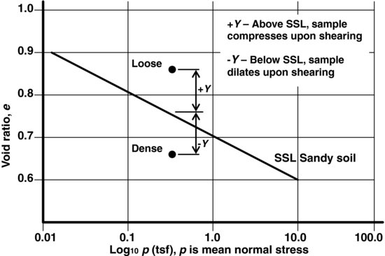
The proportion of shearing stresses versus compressive stresses generated beneath our theoretical small and large footings also causes a problem in interpretation. Figure 3.4.1 below illustrates a steady state line with distance from the initial void ratio to the steady state line given as upsilon, Y = ei – eSSL (see Fellenius and Altaee, 1994). The upsilon parameter is also called the “state parameter” in the literature (Been and Jefferies, 1985). You can see that the distance from the initial void ratio to the SSL is a function of the mean confining stress. Loading induced soil shearing stresses generate a change in void ratio that can cause the material void ratio to reach the critical void ratio and develop steady state shearing. At the steady state line, no additional volume changes due to shearing strains will occur. Compression strains due to vertical compressive stresses do not have a similar limit value, although very high compression stresses do result in grain crushing and eventual molding of the soil into a solid mass. The amount of compression caused by an increase in vertical stresses is a function of Young's Modulus, E, which is dependent on confining stresses. Again the deeper soils have higher confining stresses which result in increased E values.
Figure 3.4.1 Definition of the upsilon parameter, Y = einitial – eSSL
Given the above discussion, notice that soil stress–strain and volume change properties depend on confining stress. The problem with the bearing capacity equation is that it suggests that soil shear strength parameters are independent of soil confining stresses, and it suggests that soil shear strength is independent of soil strains.
3.4.4.3 Footing Design Using the Load-Settlement Curve
To design a footing using the bearing capacity equation, values of soil shear strength parameters c and ![]() are required. Standard practice over the years has been to select peak values of vertical compression stress from stress–strain curves, and to plot Mohr's circle from maximum vertical and horizontal stresses on a Mohr–Coulomb plot to determine c and
are required. Standard practice over the years has been to select peak values of vertical compression stress from stress–strain curves, and to plot Mohr's circle from maximum vertical and horizontal stresses on a Mohr–Coulomb plot to determine c and ![]() values. This procedure has some inherent problems. For instance, what if one of the three tests used to draw Mohr's circle has a well-defined peak stress and the other two tests do not have peak stresses. How do you plot stresses from three compression tests when they represent different stress–strain soil performance. I've been aware for some time now, but others apparently consider it a new phenomenon that soils do not actually exhibit peak shear strength (Chu and Wanatowski, 2009). Some say that the observed peak stress in triaxial shear tests is an artifact of the testing method caused by shearing stresses induced between the ends of samples and the top and bottom platens in the triaxial test. Others, such as Dr. Bengt Fellenius (Fellenius, 2008), suggest that small footings only affect soil to shallow depth where the soil (even loose soil) behaves like an over-consolidated soil. When loaded this shallow zone soil dilates and after some strain accumulation it finally contracts, resulting in a stress-deformation curve that indicates a peak or ultimate value. I suggest that you review Holtz and Kovacs’ first edition text, An Introduction to Geotechnical Engineering, Prentice-Hall 1981, pages 496 to 503 (Holtz and Kovacs, 1981) or their second edition text 2011, pages 545 to 553 (Holtz, Kovacs and Sheahan, 2011).
values. This procedure has some inherent problems. For instance, what if one of the three tests used to draw Mohr's circle has a well-defined peak stress and the other two tests do not have peak stresses. How do you plot stresses from three compression tests when they represent different stress–strain soil performance. I've been aware for some time now, but others apparently consider it a new phenomenon that soils do not actually exhibit peak shear strength (Chu and Wanatowski, 2009). Some say that the observed peak stress in triaxial shear tests is an artifact of the testing method caused by shearing stresses induced between the ends of samples and the top and bottom platens in the triaxial test. Others, such as Dr. Bengt Fellenius (Fellenius, 2008), suggest that small footings only affect soil to shallow depth where the soil (even loose soil) behaves like an over-consolidated soil. When loaded this shallow zone soil dilates and after some strain accumulation it finally contracts, resulting in a stress-deformation curve that indicates a peak or ultimate value. I suggest that you review Holtz and Kovacs’ first edition text, An Introduction to Geotechnical Engineering, Prentice-Hall 1981, pages 496 to 503 (Holtz and Kovacs, 1981) or their second edition text 2011, pages 545 to 553 (Holtz, Kovacs and Sheahan, 2011).
Rather than deal with the problems of selecting a peak strength, reduced strength, residual strength, or a strength at a given soil strain to use in their bearing capacity equation analyses, engineers are starting to turn back to the load-settlement curve method (Fellenius, 2008; Briaud, 2007) which is similar to the full scale footing load test methods used prior to 1925. If you think about it, why do we perform load tests on pile foundations and analyze pile load-settlement curves, and then turn around and use the bearing capacity equation for a deep footing? Why not develop load-settlement curves for both types of foundations?
References
Been, K. and Jefferies, M.G. (1985) A state parameter for sands. Geotechnique, 35, 99–112.
Bowles, J.E. (1968) Foundation Analysis and Design, 1st edn, McGraw Hill Inc., 659 pages.
Bowles, J.E. (1982) Foundation Analysis and Design, 3rd edn, McGraw Hill Inc., 816 pages.
Bowles, J.E. (1996) Foundation Analysis and Design, 5th edn, McGraw Hill Inc., 1024 pages.
Briaud, J.L. (2007) Spread footings in sand: load settlement curve approach. Journal of Geotechnical and Geoenvironmental Engineering, 133(8), 905–920.
Chu, J. and Wanatowski, D. (2009) Effect of loading mode on strain softening and instability behavior of sand in plane-strain tests. American Society of Civil Engineers, GeoInstitute, Journal of Geotechnical and Geoenvironmental Engineering, 108–120.
Fellenius, B.H. and Altaee, A. (1994) Stress and settlement of footings in sand. Proceedings of the American Society of Civil Engineers, ASCE, Conference on Vertical and Horizontal Deformations for Foundations and Embankments, Geotechnical Special Publication, GSP, No. 40, College Station, TX, June 16 - 18, 1994, Vol. 2 pp. 1760–1773.
Fellenius, B.H. (2008) Foundation Design Approach of Past, Present and Future. Geo-Strata Magazine, November/December 2008, pp. 14–17.
Holtz, R.D. and Kovacs, W.D. (1981) An Introduction to Geotechnical Engineering, 1st edn, Prentice-Hall, Inc., Englewood Cliffs, New Jersey, 733 pages.
Holtz, R.D., Kovacs, W.D. and Sheahan, T.C. (2011) An Introduction to Geotechnical Engineering, 2nd edn, Pearson, Prentice-Hall, 853 pages.
Meyerhof, G.G. (1956) Penetration tests and bearing capacity of cohesionless soil. Journal of Soil Mechanics and Foundation Division of the American Society of Civil Engineers, 82(SM 1), 1–19.
Peck, R.B., Hanson, W.E., and Thornburn, T.H. (1953) Foundation Engineering, 1st edn, John Wiley & Sons, 410 pages.
Peck, R.B., Hanson, W.E., and Thornburn, T.H. (1974) Foundation Engineering, 2nd edn, John Wiley & Sons, 514 pages.
Terzaghi, K. (1943) Theoretical Soil Mechanics, John Wiley & Sons, Inc., New York, 528 pages.
Terzaghi, K. and Peck, R.B. (1948) Soil Mechanics in Engineering Practice, John Wiley & Sons, Inc., New York and Chapman & Hall, Ltd., London, 566 pages.
Wu, T.H. (1966) Soil Mechanics, Allyn and Bacon, Inc., Boston, 431 pages.
1. A word about net versus gross bearing pressure is required. Most geotechnical engineers intend that their allowable bearing pressure be used to size the column footing by dividing the service loading by the bearing pressure to determine the required footing area. They assume that soil and concrete weigh “about” the same and that the soil removed to construct the footing weighs essentially the same as the concrete that replaces it in the ground. Structural engineers must be related to accountants because they take every pound into account and assume the recommended allowable bearing pressure is “gross” pressure. They often subtract the weight of the footing and the weight of any surcharge soil loading above the bearing surface from the allowable bearing pressure to determine the net bearing pressure for use in footing design.